aldes EVEREST XV User manual

Download the settings guide from our website or directly from the SD card provided.
www.aldes.com
EVEREST XV Installation instructions
EN

2
TABLE OF CONTENTS
1. RECOMMENDATIONS AND SAFETY INSTRUCTIONS ..........................................................................................4
1.1 Personal protection ............................................................................................................................................4
1.2 Precautions for installation and maintenance .................................................................................................4
2. Installation.................................................................................................................................................................5
2.1 General.................................................................................................................................................................5
2.2 Transport on site .................................................................................................................................................5
2.3 Parts supplied in packaging...............................................................................................................................6
2.3.1 Document pouch ..........................................................................................................................................6
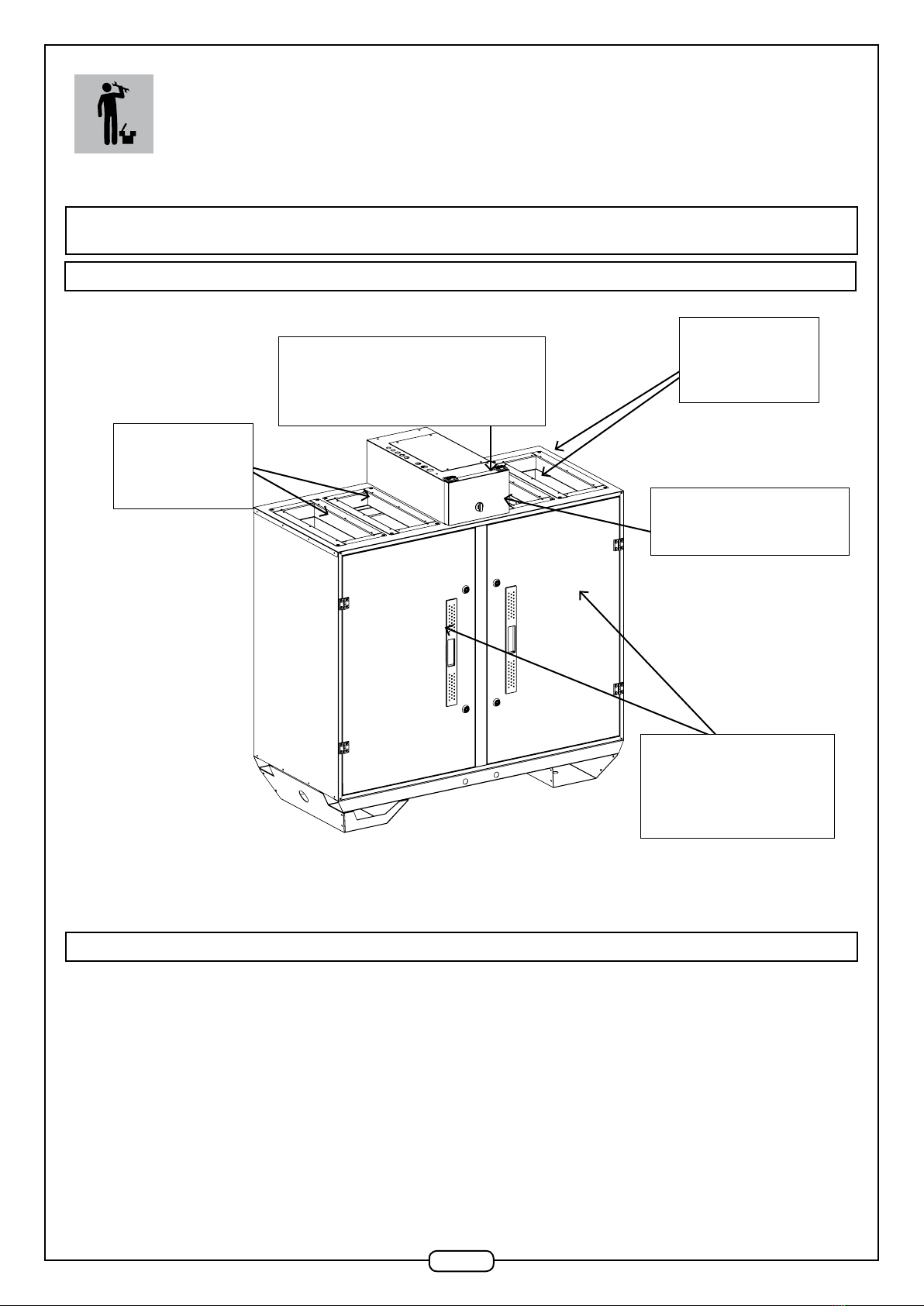
2.4 Installing the Unit ................................................................................................................................................7
2.4.1 General..........................................................................................................................................................7
2.5 Airflow direction..................................................................................................................................................7
2.5.1 Right side version .........................................................................................................................................7
2.5.2 Left side version............................................................................................................................................7
2.6 Assembling options / accessories ....................................................................................................................8
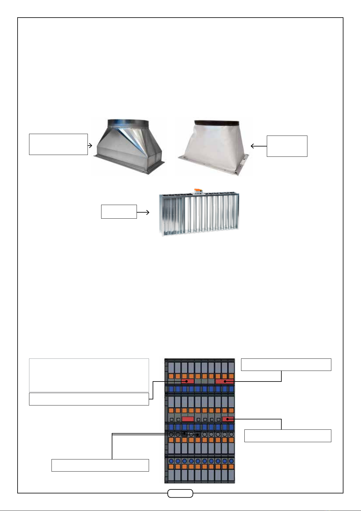
2.6.1 Connecting adapter pieces...........................................................................................................................8
2.6.2. Fitting an insulation damper on fresh air / discharged air duct ..................................................................8
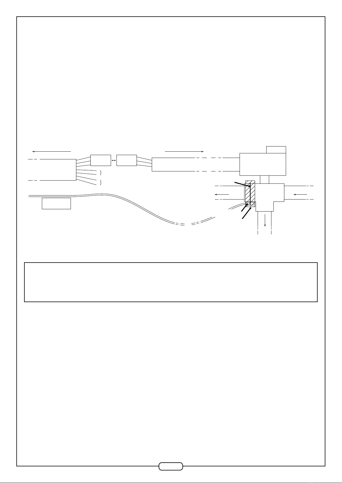
2.6.3 Connecting standard or insulated exible sleeves ......................................................................................9
2.6.4 Connecting the CO2sensor .........................................................................................................................9
2.6.5 Optional internal water coil .........................................................................................................................10
2.6.6 Constant pressure option ...........................................................................................................................10
2.6.7 LON option......................................................................................................................................................11
2.7 Hydraulic connection........................................................................................................................................11
2.7.1 Connecting condensate drains - general....................................................................................................11
2.7.2 Connecting the heat exchanger condensate drain.....................................................................................12
2.7.3 Connecting the cooling coil condensate drain ...........................................................................................12
2.7.4 Connecting the internal water coil collectors..............................................................................................12
2.8 Connecting to mains power.............................................................................................................................12
2.8.1 Control principle - Power............................................................................................................................13
2.8.2 Connecting electrical cables - power or control.........................................................................................14
2.8.3 Unit mains power supply (single-phase).....................................................................................................15
2.8.4 Connecting the power supply to the frost-protection coil or heating coil (optional)...................................15
2.9 Servicing filters .................................................................................................................................................16
2.10 Configuring the TCP/IP protocol ...................................................................................................................16
2.11 Remote control communication....................................................................................................................20
2.11.1 Using the remote control ..........................................................................................................................20
2.11.2 Menu access.............................................................................................................................................20

3
3. DIMENSIONS...........................................................................................................................................................21
3.1 Unit dimensions ................................................................................................................................................21
3.2 Dimensions of external accessories ..............................................................................................................22
3.2.1 Flexible sleeves...........................................................................................................................................22
3.3 Adapter piece drawings .................................................................................................................................23
3.4 Diameters of internal water coil collectors ....................................................................................................24
4. CONTROL OPTIONS...............................................................................................................................................25
4.1 Hard-wired control options..............................................................................................................................25
4.2 Modbus addresses ...........................................................................................................................................26
NOTES..........................................................................................................................................................................27

4
Please this notice carefully before installing the equipment and keep it in good condition near to the device throughout its life time.
1.1 Personal protection
• This device may be used by children over the age of 8 and by persons with impaired physical, sensory or mental capacities or without experience or
knowledge, if they are suitably supervised of if they are provided with instructions concerning the safe use of the device and they have understood
the risks involved.
• Children should not be allowed to play with the device. User cleaning and servicing should not be done by children without suitable supervision.
1.2 Precautions for installation and maintenance
• Installing an EVEREST unit may present risks due to live electrical elements or moving mechanical parts. The equipment must be installed, activated
and repaired by trained and qualied technicians, in full respect of applicable standards and best practices.
• Any servicing or maintenance operation requiring the access doors to be opened or any component of the unit to be removed must only be carried
out by qualied technicians.
• Electrical connections for the equipment shall be made by a professional in accordance with standard NF C 15-100.
• In particular, a cut-off switch with an opening distance of at least 3 mm on each pole and a circuit breaker with a suitable trip rating shall be installed
in the xed wiring installation. The copper conductor cross-sections are dened in sections 1.9.3, 1.9.4 and 1.9.5 of this installation notice.
• The electrical power supply to the device must be disconnected prior to any maintenance or cleaning operation.
• Ensure that the unit may not be turned on accidentally.
• If a power cable is damaged, it must be replaced by the professional tter who installed the product or by a similarly-qualied person, to prevent any
danger.
• If the motor overheats, it will reduce its modulation on a linear basis. If the motor exceeds its maximum admissible internal temperature, the control-
ler will stop the motor and automatically restart it after it has cooled down. In the event of a motor fault (signal fault in the motor’s integrated circuit,
phase failure, motor blockage, short circuit to Earth or internal short circuit, intermediate or network undervoltage or overvoltage, peak current fault),
an alarm will cause the unit to shutdown. Cut off the power supply (circuit breaker on switchboard), check that nothing is preventing the unit from
operating correctly (e.g. blockage, rubbing, clogged wheel, abnormal noise, etc.) and wait one hour before re-energizing the unit.
• If the problem persists, contact your tter or vendor.
• Use only ofcial spare parts provided by the manufacturer.
• For units equipped with an electrical heating coil: in the event of multiple failure of the electrical coil control (failure of at least two sensors) and in
the event of overheating in the air supply compartment (ambient temperature > 85 °C), an auto-reset thermostat will cause the electrical coil to shut
down. The electrical coil is equipped with a manual-reset thermostat triggered at 120 °C.
• To ensure the guarantee is effective, the unit must not be modied in any way.
• Ensure the unit is serviced regularly to ensure it operates correctly.
1. RECOMMENDATIONS AND SAFETY
INSTRUCTIONS

5
2.1 General
Attention: the purpose of this document is to provide instructions on the installation of the unit. To ensure the installation is fully compliant, refer to
applicable legislation in effect in the country of installation (e.g. NF DTU 68-3 part 1.1.4).
• Access points
Access door to
internal components,
protected with an 8
mm Hex cap key
Top:
2 opening
frames
Quick access hatch
to PCB and switches
Screw-fit access hatch
Terminal block for power
supply and control system
The unit identication plate is provided in duplicate. One plate is located on the back of the quick access hatch and another is on the side panel.
The unit is packaged in plastic lm, protected with cardboard corner pieces. All accessories ordered with the unit are delivered unassembled. Refer to
section 2.6 for tting accessories.
Attention: do not drill the panel between the two access doors, nor the base plates as they support the cable bundles!
2.2 Transport on site
The unit is mounted on cross-pieces. When transporting using a forklift, ensure that the forks are long enough for all the spars to rest on them. En-
sure that the cross-pieces are not damaged when the forks are passed under the unit (ensure minimum clearance of 350 mm for the XV1600 and the
XV2300).
2. INSTALLATION
Top:
2 opening
frames
Caution: the unit is designed for indoor use.

6
Spars
Cross-pieces
Distance between forks min. 350 mm
Handling with slings: use the handling bars placed in the cross-pieces. The exural rigidity of the bars should be suitable for the weight of the unit.
Place the loops of the slings around the handling bars and place the spacers above the unit to prevent damage to the structure. See diagram below.
Spacers
Slings
Handling bars
2.3 Parts supplied in packaging
2.3.1 Document pouch
All instructions concerning usage of the unit are stored in the air supply compartment.
An SD card with a USB adapter containing the control instructions and the software conguration is provided in the pouch.

7
2.4 Installing the Unit
2.4.1 General
Position the cross-pieces on a at, stable surface (at oor for condensate).
We recommend that you install an anti-vibration device between the feet of the Unit and the oor (e.g. anti-vibration mountings or mat) and between
the branch connections and the air ducts (e.g. exible sleeve) to attenuate any vibrations generated by the fans.
When installing the Unit and connecting ducts and electric cables, ensure that you do not block access points, so that internal functional elements can
be easily removed and that the unit can be correctly cabled.
Space required for servicing: the two side doors must be able to open to a minimum of 90° to enable replacement of the lters. The central black door
must open to an angle of 180° to enable access to switches and the control system.
NB: The electrical box has an IPX2 protection rating subject to the cable glands being securely closed, the electrical connection panel being screwed
shut and the quick access hatch to the switches being closed with a quarter-turn. To avoid any risk of condensation of ambient air on the fresh air ducts,
and to improve unit performance, we strongly recommend that all ducts are insulated.
2.5 Airflow direction
A right side and a left side version exist.
2.5.1 Right side version
Internal airow direction to the right
2.5.2 Left side version
Internal airow direction to the left
Fresh air
Discharge
Air exhaust
Air supply
Fresh air
Discharge
Air exhaust
Air supply

8
2.6 Assembling options / accessories
The ceiling is tted with M8 inserts on each corner of the opening frame to accommodate external accessories: adapter pieces - insulated exible
sleeves - rigid exible sleeves - dampers. Each accessory is delivery with screws.
Protective foam should be installed between the accessories and opening frames to ensure an airtight junction between the elements.
Adapter pieces
2.6.1 Connecting adapter pieces
Adapter pieces are supplied with 4 screws, washers and M8 nuts. As necessary, screw each adapter piece into the in-
serts on the opening frames or on the insulation dampers, by assembling washer, screw and nut in each assembly corner.
To connect circular ducts, they must be tted with a rubber O-ring seal. Refer to the diameters for each machine in section 3.3.
Insulate the ducts and adapter pieces in accordance with applicable standards and regulations.
2.6.2. Fitting an insulation damper on fresh air / discharged air duct
Dampers are supplied with pre-wired servo-motors, an RG link cable (whether one or two dampers are present), a junction box and M8 screws.
Fit an airtight seal on each opening frame. Screw each damper into the inserts on the opening frame.
Connect the RG cable to the RG1 - RG2 terminals on the terminal block (see diagram below), ensuring beforehand that the cable is passed through the
cable gland on the electrical box, to ensure the IPX2 rating. For technical data concerning the terminals, refer to section 2.8.2.
Wiring diagram for RG cable to terminal block:
Flexible
sleeve
Dampers
Quick-connect terminal -
cable cross section 0.14 to 1.5 mm² -
rigid connector or crimped end piece
recommended
M17
RG2
M5
M3
M8
M36
M34
-24
-24
M16
+24
+24
M35
M37
M7
M4
M4
RG1
M12
Tver
RG2
M4
M4
M8
M34
M36
+24
M17
Fus
M33
M35
M37
M7
M4
M4
M32
M16
M12
Horizontal 3-terminal bridge
Vertical 2-terminal bridge
Vertical 3-terminal bridge
Horizontal 2-terminal bridge

9
Wiring diagram - junction box:
2.6.3 Connecting standard or insulated flexible sleeves
Flexible sleeves are available in the standard version (one layer of glass bre, re resistance rating M0) or insulated version (two layers of glass bre,
insulated with a 5 mm glass wool felt), supplied with 4 M8 screws, 8 washers and 4 nuts. The sleeve may be xed to a damper or directly to the opening
frames. For sleeve dimensions, refer to section 3.2.1.
Screw each exible sleeve into the inserts of the opening frame or on to the insulation dampers, by tting the washer, screw and nut in each assembly
corner. Insulate the ducts in accordance with applicable standards and regulations.
2.6.4 Connecting the CO2sensor
The CO2 sensor is supplied as an accessory. It must be connected to the terminal
block according to the diagram below (24 V AC / GND and 1-10V input).
3-way connector
3-way connector
Damper servo-motor cable
RG cable
To damper
To terminal block
3-way connector
3-way connector
Damper servo-motor cable
RG cable
To damper
To terminal block
Black
Red
CO2 sensor
123456
+V GND RH T CO2 GND
24V AC GND 0-10V GND
Control terminal connection
Labels Definition Comments
M17 Air supply temperature sensor Sensor connected in factory
M16
M12 CO2 sensor – 010 V Active if option selected
M4 GND Bridged by default on terminal block
M5 CTA external shutdown
M4 GND NO
M3 High speed
M8 Fire Alarm contact Bridged by default on terminal block
M7 GND
M34 CTA Alarms (A) return relay NO
M35
M36 CTA Alarms (B) return relay NO
M37
RG1 Fresh air damper relay -
ON/OFF NO (Active if option selected)
RG2
+24 24V AC Damper servo-motors
-24
+24 24V AC CO2 probe
-24
Single damper
New air or exhaust air 2 dampers in parallel
New air or exhaust air
Junction box Junction box

10
2.6.5 Optional internal water coil
The internal water coils are supplied with two at seals, a motor-driven and pre-wired 3-way valve, a BW control wire and a frost-protection tempera-
ture sensor (to measure the temperature of the uid circulating in the coil). The at seals and the 3-way valve are for the time being left in the optional
accessories box. The BW wire and the frost-protection sensor are connected at one end to the control terminal block. They are left unattached at the
other end, ready to be installed.
Make the hydraulic connection for the water coil, where the inlet and outlet are on the side wall. Connect the 3-way valve to the coil water circuit. Once
the hydraulic connections are made, connect the wires for the internal water coil (refer to wiring diagram below).
Servo-motor and 3-way valve assembly diagram:
1
2
3
4
5
6
7
To Unit connection terminal block
BW cable
Temperature
sensor
on 3-way valve
Heat pump - ON/OFF
Male
3-point
connector
Female
3-point
connector Servo-motor cable 3-way valve
To 3-way valve
Clip collar
Coil water circuit
Temperature
sensor
Insulation
3-way valve
Servo-motor
Coil water circuit
Cooling pump - ON/OFF
Attach the BW male connector to the female connector on the servo-motor (strands 1, 2, and 3 of the BW cable).
If so desired, attach the 4 free strands of the BW cable used to control the stop or start functions of the hot or cold water coil circuit pump.
Caution: the electrical connections of external devices or which are located in a humid environment must be watertight. We recommend that you
protect the connections between the servo-motor cable and the BW cable, using at least an IPX5 protection.
Attach the temperature sensor to the 3-way valve of the internal coil using a plastic collar. To increase the precision of uid temperature measurement,
insulate the sensor and the 3-way valve.
2.6.6 Constant pressure option
The kit contains 3 x RJ12 cables (labelled R8, R9, R10) connected to the 2 PTH pressure sensors. Each sensor is connected to 2 metres of transparent
exible tube, itself connected to a black pressure inlet. 4 self-tapping screws are supplied in a plastic bag. The whole assembly is factory pre-wired
and supplied in the box of optional accessories.
The exhaust PTH sensor is intended to measure the difference in pressure between the exhaust duct and the ambient air. Its address pointer is posi-
tioned on 6. The transparent tube is connected to the negative terminal (-) of the sensor (duct under negative pressure). Leave the positive terminal (+)
free. Drill a Ø10 mm hole in the exhaust duct to insert the pressure inlet. Fix the pressure inlet in place using the two self-tapping screws. Ensure there
is an airtight seal around each pressure inlet.
The air supply PTH sensor is intended to measure the difference in pressure between the air supply duct and the ambient air, outside the unit. Its ad-
dress pointer is positioned on 5. The transparent tube is connected to the negative terminal (-) of the sensor (duct under negative pressure). Leave the
negative terminal (-) free. Drill a Ø10 mm hole in the exhaust duct to insert the pressure inlet. Fix the pressure inlet in place using the two self-tapping
screws. Ensure there is an airtight seal around each pressure inlet.

11
Caution: the transparent tubes must descend from the pressure inlet of the PTH sensor to the black pressure inlet on the duct without a low bend
that may cause a water trap. Under certain conditions, the air in the tube may condensate. Water stagnating in the tube would cause incorrect
measurements and therefore incorrect control of the unit!
Caution: to obtain the best possible results, the pressure must be measured where there is least risk of turbulence, i.e. on a straight section of duct.
The minimum distance to respect from any source of perturbation is at least twice the diagonal of a rectangular cross-section and at at least twice the
diameter of a circular cross-section.
2.6.7 LON option
The kit contains 2 x RJ12 cables, a, RJ12 split (2 female inputs →1 female output) and an OJ Air2 LON module. The whole kit is factory pre-wired and
connected to the connection terminal block.
Connect the RJ12 cable labelled R11 waiting on the spar to one of the two female RJ12 connectors on the LON module.
The LonWorks networks cable is connected to the OJ Air2 LON module via the PTR 2-point connector on the module.
2.7 Hydraulic connection
2.7.1 Connecting condensate drains - general
All condensate drains must be connected to a water trap (plate heat exchanger and cooling coil optional). The water traps are delivered with each unit,
in a box placed inside the unit. The membrane water traps are used to eliminate the negative pressure in the device, so as to enable the drainage of
condensate or to prevent an air leak from the unit.
NB: to prevent the risk of freezing in winter, insulate the water trap and the drain accessories if they are located in a non-heated area!
Membrane water trap
Condensate drain
direction
Exhaust sensors
Address pointer on 6
Sloping transparent hose
to black pressure inlet
No low bends!
Air supply sensor
Address pointer on 5

12
2.7.2 Connecting the heat exchanger condensate drain
Our condensate collection trays are tted with a drain that passes through the oor, comprising a plug and a PVC pipe Ø32. The membrane water trap
is delivered in the box of separate parts. Connect the membrane water trap to the evacuation pipe.
Attention: Respect the condensate drainage direction indicated by an arrow on the connector.
2.7.3 Connecting the cooling coil condensate drain
Our cooling coil condensate collection trays are tted with a plug attached to an extendible hose discharging at the access panel spar under the cool-
ing coil. The end of the PVC hose has a male Ø32 end piece. Connect the discharge hose to a water trap (refer to section 2.8.1) by attaching a female
PVC Ø32 end piece.
2.7.4 Connecting the internal water coil collectors
Refer to section 3.4 for collector diameters and their positions.
Collectors have a standard thread. Attach the water inlets and outlets on the coil collectors.
The collector water inlets and outlets are identied on the side panels of the Unit (the water circuit always runs counter to the air circuit on a coil con-
taining at least two rows). We recommend that you hold the collector with a clamp while connecting it, to prevent damage to the collector that could
cause leaks.
Ensure the joints on the collectors are sealed and use an expansion seal or exible connection to absorb any expansion or contraction.
Refer to section 3.4 for nominal diameters of the 3-way valves.
NB: Coils admit a maximum pressure of 8 bar.
2.8 Connecting to mains power
Caution: electrical connections should be made by a qualied electrician equipped with suitable Personal Protective Equipment. Never perform work
on the Unit while it is energized. The electrical connection shall respect NF-C 15-100. Each power supply network must be protected with an omni-pole
circuit breaker with an opening distance of 3 mm on each contact. For a single-phase power supply, use a type A differential leak current circuit breaker.
For a 3-phase supply, use a type B circuit breaker. We recommend a differential of 300 mA for these two types of power supply. The amperage rating
required for each circuit breaker according to the size of the Unit is dened in sections 2.8.3 and 2.8.4. Maximum recommended ambient temperature
< 45 °C. Remember to connect to the Earth circuit.
Plug
PVC hose Ø 32 mm
Membrane water trap
Ø 32 mm female

13
2.8.1 Control principle - Power
Each unit has an electrical control box on its roof. This box contains the power and control components, and features two access hatches:
- One screwed hatch for the electrical connections (power and control)
- One quarter-turn locking hatch for access to the PLC and switch connections
Refer to the diagram below.
The Unit has a general power supply circuit and one circuit for each electrical coil. Each circuit has its own switch located behind the quick access
hatch.
The terminal blocks for the power and control components are separated by the transformer. The transformer is protected by fuses upstream (1 A) and
downstream (2.5 A).
Access to connection terminal block
(screwed)
Power supply (mains + electrical coil), sensor,
control options
Quick access
PLC and switch connections
Access to control terminal blocks
Access to power terminal blocks
PowerControl system
Access to SD card - RJ45 cable - RJ12 Access to switch Optional terminal blocks
for coils
Power fuse
Power terminal block
Power supply -
distribution
Control terminal block Control fuses
Optional:
Extension control power supply
Control terminal block Transformer Connection box
Optional: Frost-
protection coil power
switch (400 V 3-phase)
Optional: Internal
electric coil power
switch
(400 V 3-phase)
Unit power supply switch
(single or 3-phase)
Master control PLC

14
2.8.2 Connecting electrical cables - power or control
Unscrew the cross-head screws on the access hatch to the terminal block. Pass the power supply cables through the cable glands to ensure air
tightness.
Cable gland for
control system cable
The power supply cable rigid conductors or with end pieces are directly connected to the spring terminals (no tools required). It is possible to release
the conductors using a screwdriver to actuate the orange latch in front of the conductor insertion hole.
The exible conductors without end pieces must be inserted by actuating the latch to release the spring (see photo below).
By applying a light effort on the latch, you can verify that the conductor is correctly inserted if the latch recedes 1 mm without resistance.
The bridges slot into the purpose-built holes in the terminal (see photo below).
Connecting a conductor to a terminal Connecting a bridge to a terminal (for inlet/outlet dampers)
3-terminal bridge 2-terminal bridge
Cable gland for
power cable

15
2.8.3 Unit mains power supply (single-phase)
We recommend a circuit breaker with a 20 A rating and a 300 mA differential sensitivity and a minimum cable cross-section of 1.5 mm² for the mains
power supply. See wiring diagram below:
Unit power supply
Models Power supply Frequency Max. power
consumption (W) Terminal type
XV 600 1~ 230 V AC + E 50/60 Hz 1100 Quick-connect
terminal - cable
cross section 0.14
to 4 mm² - rigid
connector or
crimped end piece
recommended
XV 1200 1~ 230 V AC + E 50/60 Hz 1200
XV 1600 1~ 230 V AC + E 50/60 Hz 1300
XV 2300 1~ 230 V AC + E 50/60 Hz 1420
2.8.4 Connecting the power supply to the frost-protection coil or heating coil (optional)
We recommend a circuit breaker with a 20 A rating and a 300 mA differential sensitivity, along
with a cable cross-section of 2.5 mm².
Electric coil power supply
Models Power supply Frequency Max. power
consumption (W) Terminal type
XV 600 3~ 400 V AC +N +E 50 Hz 1700 Quick-connect
terminal - cable
cross section 0.5
to 10 mm² - rigid
connector or
crimped end piece
recommended
XV 1200 3~ 400 V AC +N +E 50 Hz 3400
XV 1600 3~ 400 V AC +N +E 50 Hz 5650
XV 2300 3~ 400 V AC +N +E 50 Hz 7500
Power
terminal connection
Single-phase unit power
supply 230 V + E:
- 2 fans
air exhaust / air supply
- PLC
B1T
B1N
B1L
B2T
B2N
B2L
Connection to frost-protection
coil power terminal block
Alimentation triphasée
batterie Dégivrage
3 x 400V +N +T
B6T
B6N
B6L3
B6L2
B6L1
PE
L
N
L1
L2
L3
PE
N

16
Attention: Each coil is controlled by a static relay. The static relay is likely to generate interference. The use of mains lters may be necessary in the
event that the user needs to satisfy EMC requirements (EN/IEC standard).
- Unit XH1000 to XH3500: lter 220nF / 760V /X1
2.9 Servicing filters
Caution: lters must only be serviced with the unit de-energized, by a technician with suitable qualications (live LV conductor).
To check how clogged the lters are, we recommend that you use a pressure sensor (optional extra).
We recommend that the lters be changed when the nal pressure losses reach the following levels:
G4 lters: max. 250 Pa
F7 at lters: 250 Pa ECO - max. 450 Pa
F7 HE lters: 250 Pa ECO - max. 450 Pa
Consult the conguration notice to reset the pressure loss when changing the lters under a dynamic alarm.
2.10 Configuring the TCP/IP protocol
Connect the RJ45 cable to the TCP/IP socket on the Master PCB:
1) Using the remote control, obtain the IP address of the control system, the subnetwork
mask, the gateway and the DNS server as follows:
- User / Internet
- (To change windows use the control wheel. To alter a value, press the central button and
turn the control wheel to the required value).
- Static/Dynamic IP:
• Use Static if there is a direct connection between the PC and the Unit
• Use Dynamic if a router is used for the connection
- Examples:
• Default IP address, e.g.: 172.20.20.3
• Default subnetwork mask, e.g.: 255.255.255.0
• Default gateway, e.g.: 172.20.20.1
• DNS server required e.g.: 172.20.20.3 (identical to IP address)
• Auxiliary DNS server 0.0.0.0

17
2) On the PC, congure the IP address and DNS server address. Two paths are possible depending on the version of Windows:
a. with Windows XP
- Start/Connections / Display all connections / right-click“local area connection” / Properties:
- Internet Protocol / Properties:

18
b. with Windows 7
- Conguration panel / Network and
Internet / Network and Sharing Centre
-Local network connection / Properties
- Click IP v.4 / Properties

19
c. Congure the IP address (Windows XP and 7)
- IP address: Create an IP address for the PC other than that of
the PCB. Caution, this PC IP address must use the same rst
three sections of the PCB IP address, e.g.:
PCB IP address = 172.20.20.3;
PC IP address = 172.20.20.4.
- Subnetwork mask: Identical to that of the PCB: 255.255.255.0
(identical to PCB)
3) Open a web page using Internet Explorer and enter the IP address of the PCB:
- The next page is displayed:
- Enter the user name and password depending on your prole:
User:
• Name: USER
• Password: 111
Installer:
• Name: INSTALLE
• Password: 222
Service:
• Name: SERVICE
• Password: 333
- For more information on conguring the control system, refer to the conguration instructions.
- Once the PCB IP address is entered, if the webserver page is not displayed, this may be due to the proxy.

20
2.11 Remote control communication
2.11.1 Using the remote control
Wheel
Help
ESC
Rotate the wheel to browse a menu. Press the wheel to select a menu. Press ESC to quit a menu.
2.11.2 Menu access
- To access the User level no password is required.
- To access the Installer level, enter the password: 1 1 1 1.
- To access the Service level, enter the password: 1 1 1 2.
Table of contents
Other aldes Heating System manuals
Popular Heating System manuals by other brands

Hotstart
Hotstart DLV Installation & operation manual

DEFA
DEFA WarmUp Bluetooth Fitting instructions

FläktGroup
FläktGroup MINIMASTER RDKS INSTALLATION, OPERATION, MAINTENANCE AND SPARE PARTS

Tecnoclima
Tecnoclima SR-UT Series TECHNICAL INFORMATION ASSEMBLY, USE AND MAINTENANCE INSTRUCTIONS

Fröling
Fröling Lambdamat LM 1500 KOM installation instructions

Swep
Swep Minex M10 installation manual

Vitramo
Vitramo VH Series instructions

Maico
Maico WRG 35 Mounting and operating instructions

jbc
jbc PHSE-KA instruction manual

Immergas
Immergas HYDRO Instructions and warnings

Viessmann
Viessmann VITOSOL 200-T SD2A 2m2 Series installation instructions

Marley
Marley MEnV 180 II Operating & assembly instructions