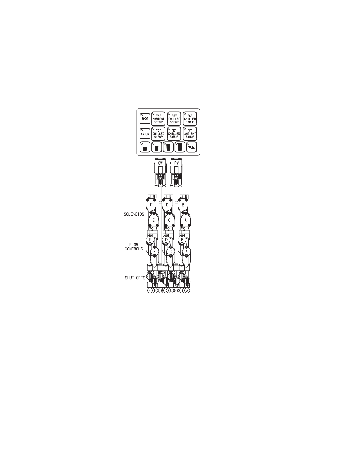
lancer 23308 SERIES User manual

LANCER ICD SERIES 23308 MANUAL PN 28-2833 - PAGE 1
ICE COOLED DISPENSER SERIES 23308
LANCER INSTALLATION GUIDE
FOR QUALIFIED INSTALLER ONLY. This basic Installation Sheet is an initial release.
If a complete Operations Manual (for the unit being installed) is required or needed,
please refer to the Lancer web site (lancercorp.com) for immediate access,
or for your convenience, scan this QR code with a mobile device (app required) for immediate access
Contact Lancer Customer Service for assistance as required.
TOOLS REQUIRED: Oetiker Pliers, Tubing Cutters, Wrench, Phillips and Slotted Screwdriver, Cordless Drill
1. INSTALLATION
1.1 RECEIVING THE UNIT
Each unit is completely tested under operating conditions and thoroughly inspected before shipment. At time of
shipment, the carrier accepts the unit and any claim for damage(s) must be made with carrier. Upon receiving
units from the delivering carrier, carefully inspect carton for visible indication(s) of damage. If damage exists, have
carrier note same on bill of lading and le a claim with the carrier.
1.2 UNPACKING
A. The ice cooled dispenser is shipped in a corrugated shipping carton. Remove the corrugated shipping carton
from the unit.
B. Remove the parts from the ice compartment.
C. Inspect the unit and parts for concealed damage. If damage exists, notify delivering carrier and le a claim.
NOTE: In order to ensure unit draingage and proper carbonation, it is necessary for the dispenser to be level,
front to back and side to side.
!
WARNING THE DISPENSER IS FOR INDOOR USE ONLY. THIS UNIT IS NOT A TOY. DISPENSER IS NOT INTENDED FOR USE BY
PERSONS (INCLUDING CHILDREN) WITH REDUCED PHYSICAL, SENSORY OR MENTAL CAPABILITIES, OR LACK OF
EXPERIENCE AND KNOWLEDGE, UNLESS THEY HAVE BEEN GIVEN INSTRUCTION CONCERNING USE OF THE APPLIANCE BY A
PERSON RESPONSIBLE FOR THEIR SAFETY. UNIT IS NOT DESIGNED TO DISPENSE DAIRY PRODUCTS. THE MIN/MAX AMBIENT
OPERATING TEMPERATURE FOR THE DISPENSER IS 40°F TO 90°F (4°C TO 32°C).
ADVERTENCIA EL DISPENSADOR SÓLO DEBE USARSE EN INTERIORES. ESTA UNIDAD NO ES UN JUGUETE. ESTA UNIDAD NO
ESTÁ DESTINADA AL USO POR PARTE DE PERSONAS (INCLUSO NIÑOS) CON CAPACIDAD FÍSICA, SENSORIAL O MENTAL
REDUCIDA, O SIN EXPERIENCIA Y CONOCIMIENTOS SUFICIENTES, A MENOS QUE UNA PERSONA RESPONSABLE DE SU
SEGURIDAD LES HAYA DADO SUPERVISIÓN O CAPACITACIÓN EN EL USO DE LA UNIDAD. ESTA UNIDAD NO HA SIDO DISEÑADA
PARA SUMINISTRAR PRODUCTOS LÁCTEOS. LA TEMPERATURA AMBIENTE OPERATIVA MÍNIMA / MÁXIMA PARA EL
DISPENSADOR ES DE 40°F A 90°F (4°C A 32°C).
AVERTISSEMENT LE DISTRIBUTEUR EST DESTINÉ À UN USAGE À L’INTÉRIEUR SEULEMENT. CET APPAREIL N’EST PAS UN
JOUET. IL NE DEVRAIT PASÊTRE UTILISÉ PAR DES ENFANTS OU DES PERSONNES INFIRMES SANS SURVEILLANCE. CET
APPAREIL N’EST PAS DESTINÉ À UN USAGE PAR DES PERSONNES (Y COMPRIS LES ENFANTS) AYANT DES CAPACITÉS
PHYSIQUES, SENSORIELLES OU MENTALES RÉDUITES, OU MANQUANT D’EXPÉRIENCE ET DE CONNAISSANCES, À MOINS
QU’ELLES OBTIENNENT DE LA SURVEILLANCE OU DES INSTRUCTIONS AU SUJET DE L’UTILISATION DE L’APPAREIL DE LA
PART D’UNE PERSONNE CHARGÉE DE LEUR SÉCURITÉ. CET APPAREIL N’EST PAS CONÇU POUR DISTRIBUER DES PRODUITS
LAITIERS. LA TEMPÉRATURE DE SERVICE AMBIANTE MINIMUM/MAXIMUM POUR LE DISTRIBUTEUR ESTDE 40°F À 90°F (4°C À
32°C).
!
WARNING TO AVOID PERSONAL INJURY OR DAMAGE, DO NOT ATTEMPT TO LIFT A UNIT WITHOUT HELP. FOR HEAVIER UNITS,
USE OF A MECHANICAL LIFT MAY BE APPROPRIATE. UNITS ARE EQUIPPED WITH AUTOMATIC AGITATION. THE UNIT MAY
ACTIVATE UNEXPECTEDLY. DO NOT PLACE HANDS, OR FOREIGN OBJECTS INTO THE ICE STORAGE COMPARTMENT. UNPLUG
DISPENSER FROM THE POWER SOURCE , WHEN UNIT IS BEING SERVICED, CLEANED, OR SANITIZED.
ADVERTENCIA EVITE LAS LESIONES PERSONALES, NO TRATE DE LEVANTAR EL DISPENSADOR SIN AYUDA. PARA LOS
DISPENSADORES MÀS PESADOS USE UN ELEVADOR MECÁNICO. LAS UNIDADES EQUIPADAS CON AGITACIÓN AUTOMÁTICA SE
ACTIVAN REPENTINAMENTE. NO PONGA LAS MANOS NI OBJETOS EXTRANOS EN EL COMPARTIMIENTO DE ALMACENAMIENTO
DE HIELO. DESENCHUFE EL DISPENSADOR DURANTE TAREAS DE SERVICIO, LIMPIEZA Y ESTERILIZACIÓN.
AVERTISSEMENT POUR ÉVITER DES BLESSURES OU DES DOMMAGES, N’ESSAYEZ PAS DE SOULEVER UNE UNITÉ SANS AIDE.
POUR LES UNITÉS PLUS LOURDES, L’UTILISATION D’UN ASCENSEUR MÉCANIQUE PEUT ÊTRE APPROPRIÉE. LES UNITÉS SONT
ÉQUIPÉES D’UNE AGITATION AUTOMATIQUE.L’UNITÉ PEUT S’ACTIVER DEMAINÉRE INATTENDUE. NE PLACEZ PAS LES MAINS,
OU DES CORPS ÉTRANGERS DANS LE COMPARTIMENT DE STOCKAGE DE GLACE. DÉBRANCHEZ LE DISTRIBUTEUR DE LA
SOURCE D’ALIMENTATION EN ÉLECTRICITÉ QUAND L’UNITÉ EST ENTRETENUE, NETTOYÉE OU ASEPTISÉE.
23308

1.3 WATER SUPPLY
A. Provide an adequate potable water supply The water supply line must be at least a 1/2 inch (12.7 mm) pipe.
Water pressure exceeding 50 PSI (0.345 MPA) is regulated by a pressure regulator on the pump deck. Water
pressure below 20 PSI (0.138 MPA) will require a booster pump.
B. Install a shut-off valve in the water line feeding the deck. If a separate water line is run for plain water, ensure
that it also has a shut-off valve.
!
CAUTION POURING COFFEE, TEA, AND LIKE SUBSTANCES INTO THE DRAIN CAN CAUSE CLOGGING.
PRECAUCIÓN VERTER EL CAFÉ, EL TÉ Y SUSTANCIAS COMO EN EL DESAGÜE PUEDE CAUSAR LA OBSTRUCCIÓN.
ATTENTION VERSER LE CAFÉ, LE THÉ ET DES SUBSTANCES COMME DANS LE DRAIN PEUT CAUSER L’OBSTRUCTION.
1.4 CARBONATOR PUMP
The carbonator pump is equipped with a strainer on the inlet side. A water supply containing any appreciable
quantity of silt, ne sand, or other debris requires a lter ahead of the pump deck. Clean the lter cartridge
periodically, depending on the condition of the water. Failure to do so may starve the pump of water, causing it to
burn out, and voiding the warranty.
1.5 ELECTRICAL SUPPLY
Locate a standard 20 AMP, 115 VAC, 60 Hz single phase electrical power outlet with ground connectors for the
power supply and pump deck.
F
WARNING CHECK THE DISPENSER SERIAL NUMBER PLATE FOR CORRECT ELECTRICAL REQUIREMENTS OF UNIT. DO NOT
PLUG INTO A WALL ELECTRICAL OUTLET UNLESS THE CURRENT SHOWN ON THE SERIAL NUMBER PLATE AGREES WITH
LOCAL CURRENT AVAILABLE. THIS UNIT MUST BE PROPERLY ELECTRICALLY GROUNDED TO AVOID POSSIBLE FATAL
ELECTRICAL SHOCK OR SERIOUS INJURY TO THE OPERATOR. THE POWER CORD HAS A THREE-PRONG GROUNDED PLUG. IF
A THREE-HOLE GROUNDED ELECTRICAL OUTLET IS NOT AVAILABLE, USE AN APPROVED METHOD TO GROUND THE UNIT.
FOLLOW ALL LOCAL ELECTRICAL CODES WHEN MAKING CONNECTIONS. EACH POWER SUPPLY MUST HAVE A SEPARATE
ELECTRICAL CIRCUIT. DO NOT USE EXTENSION CORDS. DO NOT “GANG” TOGETHER WITH OTHER ELETRICAL DEVICES ON
THE SAME OUTLET. THE KEYSWITCH DOES NOT DISABLE THE LINE VOLTAGE TO THE TRANSFORMER PRIMARY. ALWAYS
DISCONNECT POWER TO THE DISPENSER BEFORE ATTEMPTING ANY INTERNAL MAINTENANCE. ONLY QUALIFIED PERSONNEL
SHOULD SERVICE INTERNAL COMPONENTS OF ELECTRICAL CONTROL HOUSING. MAKE SURE THAT ALL WATER LINES ARE
TIGHT AND UNITS ARE DRY BEFORE MAKING ANY ELECTRICAL CONNECTIONS!
ADVERTENCIA ELÉCTRICA VERIFIQUE LA PLACA CON EL NÚMERO DE SERIE DEL DISPENSADOR, DONDE ENCONTRARÁ LOS
REQUISITOS ELÉCTRICOS CORRECTOS DE LA UNIDAD. NO ENCHUFE LA UNIDAD EN UN TOMACORRIENTE DE PARED A MENOS
QUE LA CORRIENTE INDICADA EN LA PLACA CON EL NÚMERO DE SERIE CONCUERDE CON LA CORRIENTE LOCAL
DISPONIBLE. ESTA UNIDAD DEBE ESTAR DEBIDAMENTE CONECTADO A TIERRA PARA EVITAR POSI- BLES CHOQUES
ELÉCTRICOS MORTALES O LESIONES GRAVES AL OPERADOR. AL HACER LAS CONEXIONES, RESPETE TODOS LOS CÓDIGOS
ELÉCTRICOS LOCALES. CADA DISPENSADOR DEBE TENER UN CIRCUITO ELÉCTRICO INDEPENDIENTE. NO USE
EXTENSIONES CON ESTA UNIDAD. NO LA CONECTE JUNTO CON OTROS DISPOSITIVOS ELÉCTRICOS AL MISMO
TOMACORRIENTE. EL INTERRUPTOR DE LLAVE NO CORTA EL VOLTAJE DE LÍNEA AL TRANSFORMADOR PRIMARIO.
DESCONECTE SIEMPRE LA ALIMENTACIÓN ELÉCTRICA A LA UNIDAD PARA EVITAR LESIONES PERSONALES ANTES DE TRATAR
DE REALIZAR TAREAS DE MANTENIMIENTO. EL SERVICIO DE LOS COMPONENTES INTERNOS DE LA CAJA DE CONTROL
ELÉCTRICO DEBE CONFIARSE EXCLUSIVAMENTE A PERSONAL CALIFICADO. ASEGÚRESE DE QUE TODAS LAS LÍNEAS DE
AGUA ESTÉN AJUSTADAS Y LAS UNIDADES ESTÉN SECAS ANTES DE HACER CONEXIONES ELÉCTRICAS.
AVERTISSEMENT ÉLECTRIQUE EXAMINEZ LA PLAQUE DE NUMÉRO DE SÉRIE DU DISTRIBUTEUR POUR CONNAÎTRE LES
BONNES EXIGENCES EN MATIÈRE D’ÉLECTRICITÉ POUR L’APPAREIL. NE LE BRANCHEZ PAS À UNE PRISE ÉLECTRIQUE
MURALE À MOINS QUE LE COURANT INDIQUÉ SUR LA PLAQUE DE NUMÉRO DE SÉRIE CORRESPONDE AU COURANT LOCAL
DISPONIBLE. L’UNITÉ DOIT ÊTRE MISE À LA TERRE ÉLECTRIQUEMENT POUR ÉVITER UNE DÉCHARGE ÉLECTRIQUE MORTELLE
OU DES BLESSURES GRAVES POSSIBLES À L’OPÉRATEUR. LE BLOC D’ALIMENTATION DOIT ÊTRE MIS À LA TERRE
ÉLECTRIQUEMENT COR- RECTEMENT POUR ÉVITER DES BLESSURES GRAVES OU UNE DÉCHARGE ÉLECTRIQUE MORTELLE.
LE CORDON D’ALIMENTATION A UNE FICHE À TROIS BRANCH- ES MISE À LA TERRE. SI AUCUNE PRISE DE COURANT
ÉLECTRIQUE À TROIS TROUS N’EST DISPONIBLE, UTILISEZ UNE MÉTHODE APPROUVÉE POUR METTRE L’U- NITÉ À LA TERRE.
RESPECTEZ TOUS LES CODES ÉLECTRIQUES LOCAUX LORSQUE VOUS FAITES DES CONNEXIONS. CHAQUE SOURCE
D’ALIMENTATION DOIT AVOIR UN CIRCUIT ÉLECTRIQUE SÉPARÉ. N’UTILISEZ PAS DE CORDONS PROLONGATEURS. NE
BRANCHEZ PAS PLUSIEURS APPAREILS ÉLECTRIQUES À LA MÊME PRISE DE COURANT. L’INTERRUPTEUR À CLÉ NE COUPE
PAS LA TENSION SECTEUR AU TRANSFORMATEUR PRIMAIRE. DÉCONNECTEZ TOUJOURS L’ALIMEN- TATION EN ÉLECTRICITÉ
À LA DISTRIBUTRICE AVANT DE FAIRE DE L’ENTRETIEN INTERNE. SEUL LE PERSONNEL QUALIFIÉ DEVRAIT FAIRE L’ENTRETIEN/
LA RÉPARATION DES COMPOSANTS INTERNES DANS LE LOGEMENT DES COMMANDES ÉLECTRIQUES. ASSUREZ-VOUS QUE
TOUTES LES CONDUITES D’EAU SONT ÉTANCHES ET QUE LES APPAREILS SONT SECS AVANT DE FAIRE DES CONNEXIONS
ÉLECTRIQUES!
1.6 CONNECTION OF THE EQUIPMENT
A. Position to CO2 gas tank in the desired location. Assemble the high pressure regulator to the CO2 gas tank
and run the jumper line to the low pressure regulator.
B. Attach the CO2 gas line to the carbonator by attaching the line from the high pressure regulator to the CO2
inlet. The setting of the high pressure CO2 gas regulator should be 75 PSI. Position the syrup pumps in the
desired location. Attach the CO2 gas lines leading from the low pressure regulator to these pumps.
LANCER ICD SERIES 23308 MANUAL PN 28-2833 - PAGE 2

1.6 CONNECTION OF THE EQUIPMENT(CONTINUED)
C. Connect the syrup lines from the pumps to the appropriate inlets at the front of the unit. The syrup inlets are
identied at the bottom of the unit.
D. Position the pump deck under the counter or within 75 feet of the dispenser.
E. Connect the water inlet line to the pump. Complete the water line connection between the pump and the
water inlet to the carbonator at the bottom of the dispenser.
F. Provide a suitable drain in the plumbing system and attach the 3/4 inch (1.90 cm) diameter schedule 40 PVC
drains to it. The drip pan drainage outlet is located at the right rear of the unit.
G. The ice bin drainage outlet is located at the right front of the unit.
H. Two insulated exible drain lines are provided to accommodate the drain connections.
I. Be sure to place the ice trap in the drain outlet inside the ice bin before lling with ice. This device holds the
ice away from the drain outlet, allowing the ice water to drain properly.
J. Locate the power supply and remove from carton. Follow the enclosed instructions and mount the power
supply to the dispenser base frame behind the front panel.
K. Plug in the power supply to a standard 20 AMP, 115 VAC single phase outlet. The unit will internally convert
the 115 VAC to 24 VAC.
1.7 START UP
A. After all connections to water, CO2 gas, electrical power, and syrup pumps are made, check for leaks.
B. Be sure the Bag-In-Box contains syrup.
C. Turn on water. Open the pressure relief valve on the carbonator tank by ipping up the valve cap lever, and
hold it open until water ows from the relief valve. Close (ip down) the relief valve and turn on the CO2 gas.
D. To ll all lines with water, cycle the carbonator several times by operating the dispensing valves.
E. Ensure a good ow of plain water is established from each valve.
F. Turn on CO2 at source and ensure that the HP regulator is set at 75 PSIG.
G. Operate valves until unit gases out.
H. Plug in carbonator pump motor. Pump Deck will automatically start.
!
WARNING DO NOT TURN ON THE CO2 SUPPLY AT THIS TIME. DO NOT OPERATE THE CARBONATOR PUMP DECK WITH THE
WATER SUPPLY TURNED OFF.
ADVERTENCIA NO CONECTE TODAVÍA LA ALIMENTACIÓN DE CO2. NO UTILICE LA PLATAFORMA DE LA BOMBA DE
CARBONATACIÓN CON EL SUMINISTRO DE AGUA APAGADO.
AVERTISSEMENT N’OUVREZ PAS L’ALIMENTATION EN CO2 À CE MOMENT. NE PAS FAIRE FONCTIONNER LA PLATE-FORME DE
POMPE DE CARBONATATION DE LA FOURNITURE DE L’EAU ÉTEINT.
I. Activate carbonated water valves so that the carbonator pump cycles several times and a good ow of
carbonated water is established.
J. A low pressure gas regulator controls the ow of syrup to each dispensing valve. Connect BIB connectors to
BIB’s. Set LP regulator to 65 PSIG. Activate all valves to purge air from the syrup lines.
NOTE: The unit will cycle on for 5.5 seconds, shut down, and immmediately start again and run for additional 5.5
second intervals until the water level reaches the probe.
K. The dispenser bin should now be lled with ice cubes one inch below the level of the door opening.
1.8 ADJUSTING WATER FLOW FOR LEV
The unit should have ice on the cold plate for a least one hour before you attempt to brix the valves. The drink
temperature should be no higher than 40 degrees F (4.4° C) when the ratio is set. This is done after the unit has
ice in the ice bin.
A. Slide the ID panel up until the ow controls are exposed.
B. Remove the nozzle by twisting counterclockwise and pulling down.
C. Remove the diffuser by pulling down.
D. Install Lancer yellow syrup separator (PN 54-0031) in place of the nozzle.
E. Activate the dispensing valve to ll the separator syrup tube.
F. Hold a brix cup under the syrup separator and dispense water and syrup into the cup for four seconds. Divide
the number of ounces (ml) of water in the cup by four to determine the water ow rate per second.
G. To obtain the proper ow, use a screwdriver to adjust the water ow control.
H. Repeat process for each valve.
LANCER ICD SERIES 23308 MANUAL PN 28-2833 - PAGE 3

1.8 ADJUSTING WATER TO SYRUP RATIO (BRIX) FOR LEV
A. Hold the brix cup under the syrup separator and activate valve. Check ratio (brix).
B. To obtain the proper ratio, use screwdriver to adjust syrup ow control.
C. Remove syrup separator.
D. Install diffuser and nozzle.
E. Slide ID panel DOWN.
F. Repeat process for each valve.
2. MVU OPERATION
2.1 MVU PLUMBING DIAGRAM - MAKING CONNECTIONS TO THE MVU
Positions A and F are ambient syrups only. Remove the rear cover to make these syrup connections. All other
syrups and water are fed through the cold plate connections at the front of the unit. Plumb according to the label
on the unit.
Soda/Water
Flow Controls
and Solenoids
2.2 SYSTEM STARTUP
A. Pour several drinks from each MVU to prime for beverages.
B. Prime all avor shots.
3. RECOMMENDED SERVICE AND MAINTENANCE
3.1 SCHEDULED
Daily – Section 3.4
Monthly – Section 3.5 .
Periodic Sanitizing - Sections 3.2 and 3.3
As Needed - Keep exterior surfaces of dispenser (including drip tray and cup rest) clean with a damp cloth.
3.2 CLEANING AND SANITIZING SYSTEMS
A. General Information
Lancer equipment (new or reconditioned) is shipped from the factory cleaned and sanitized according to NSF
guidelines. The operator of the equipment must provide continuous maintenance as required by this manual
and state and local health department guidelines to maintain proper operation and sanitization.
NOTE: The cleaning and sanitizing procedures below pertain to the Lancer equipment identied by this
manual. If other equipment is being cleaned, follow the guidelines established for that equipment. Cleaning
and sanitizing should be accomplished only by trained personnel. Use sanitary gloves during cleaning
and sanitizing operations. Observe all safety precautions. Follow instruction warnings on the cleaning product.
LANCER ICD SERIES 23308 MANUAL PN 28-2833 - PAGE 4

3.2 CLEANING AND SANITIZING SYSTEMS (CONTINUED)
!
CAUTION TO AVOID CONTAMINATION, DO NOT DISCONNECT WATER LINES WHEN CLEANING AND SANITIZING SYRUP LINES.
PRECAUCIÓN PARA EVITAR LA CONTAMINACIÓN, NO DESCONECTE LAS LÍNEAS DE AGUA AL LIMPIAR Y DESINFECTAR LÍNEAS
DE JARABE.
ATTENTION POUR ÉVITER TOUTE CONTAMINATION, NE PAS DÉCONNECTER LES CONDUITES D’EAU LORS DU NETTOYAGE ET
L’ASSAINISSEMENT DES CHAÎNES DE SIROP.
!
CAUTION FOLLOWING SANITIZATION, RINSE WITH END-USE PRODUCT UNTIL THERE IS NO AFTERTASTE. DO NOT USE A
FRESH WATER RINSE. THIS IS A NSF REQUIREMENT. RESIDUAL SANITIZING SOLUTION LEFT IN THE SYSTEM CREATES A
HEALTH HAZARD.
PRECAUCIÓN DESPUÉS DE LA ESTERILIZACIÓN, ENJUAGUE CON EL PRODUCTO FINAL HASTA QUE ELIMINAR EL SABOR QUE
QUEDA. NO ENJUAGUE CON AGUA FRESCA. ÉSTA ES UNA EXIGENCIA DE NSF. SI QUEDA SOLUCIÓN DE ESTERILIZACIÓN EN EL
SISTEMA, GENERA UN PELIGRO PARA LA SALUD.
ATTENTION DÉFENSE DE RINCER L’OUTIL À L’EAU FRAICHE IMMÉDIATEMENT APRÈS UN TRAITEMENT SEPTIQUE.EN CAS DE
APRÈS-GOÛT, NE PURGER AVEC LE PRODUIT FINAL UNE EXIGENCE NSF.
B. Recommended Cleaning Solution
Cleaning solutions (for example, Ivory Liquid, Calgon, etc.) mixed with clean, potable water at a temperature
of 90 to 110 degrees Fahrenheit should be used to clean equipment. The mixture ratio, using Ivory Liquid,
is one ounce of cleanser to two gallons of water. A minimum of four gallons of cleaning mixture should be
prepared.
NOTE: Extended lengths of product lines may require that an additional volume of solution be prepared.
Any equivalent cleanser may be used as long as it provides a caustic-based, non-perfumed, easily-rinsed
mixture containing at least two percent sodium hydroxide (NaOH).
C. Recommended Sanitizing Solution
Sanitizing solutions should be prepared according to the manufacturer’s written recommendations and safety
guidelines. Follow manufacturer’s requirements so that the solution provides 200 parts per million (PPM)
chlorine at a temperature of 90 degrees F to 120 degrees F. Prepare a minimum of four gallons of sanitizing
solution.
NOTE: Extended lengths of product lines may require that an additional volume of solution be prepared.
Any sanitizing solution may be used as long as it is prepared according to the manufacturer’s written
recommendations and safety guidelines, and provides 200 parts per million (PPM) chlorine.
3.3 CLEANING AND SANITIZING BAG-IN-BOX (BIB) SYSTEMS
A. Disconnect syrup quick disconnect coupling from syrup packages and connect coupling to a bag valve re
moved from an empty Bag-in-Box package.
B. Place end of syrup inlet line, with bag valve attached, in a clean container lled with clean, potable, room
temperature water.
C. Place waste container under applicable dispensing valve. Activate valve until water is dispensed. Flush and
rinse line and ttings for a minimum of 60 seconds to remove all traces of residual product.
NOTE: Extended lengths of product lines may require additional time for ushing and rinsing lines.
D. Prepare cleaning solution as described in Section 3.2 above. Place end of syrup inlet line in container lled
with cleaning solution.
E. Place waste container under applicable dispensing valve. Activate valve and draw cleaning solution through
lines for a minimum of sixty seconds. This will ensure line is ushed and lled with cleaning solution. Allow line
to stand for at least thirty minutes.
F. Place end of syrup inlet line in a clean container lled with clean, potable water at a temperature of 90 to 110
degrees F.
G. Place waste container under applicable dispensing valve. Activate valve to ush and rinse line and ttings
for a minimum of sixty seconds to remove all traces of cleaning solution. Continue rinsing until testing with
phenolpthalein shows that the rinse water is free of residual detergent.
H. Prepare sanitizing solution as described in Section 3.2 above. Place end of syrup inlet line in container lled
with sanitizing solution which has been prepared.
I. Activate valve and draw sanitizing solution through line for a minimum of sixty seconds. This will ensure line is
ushed and lled with sanitizing solution. Allow line to stand for at least fteen minutes.
J. Remove bag valve from quick disconnect coupling and reconnect syrup inlet line to syrup package. Ready
unit for operation.
LANCER ICD SERIES 23308 MANUAL PN 28-2833 - PAGE 5

3.3 CLEANING AND SANITIZING BAG-IN-BOX (BIB) SYSTEMS (CONTINUED)
K. Draw drinks and rell lines with end product to ush sanitizing solution from the dispenser.
NOTE: A fresh water rinse cannot follow sanitization of equipment. Purge only with the end use product. This is
an NSF requirement.
L. Test dispenser in the normal manner for proper operation. Taste dispensed product to ensure there is no
offtaste. If off-taste is found, ush syrup system again.
M. Repeat cleaning, rinsing, and sanitizing procedures for each valve circuit.
3.4 DAILY CLEANING - VALVES
Valves may be cleaned and sanitized (see preparation in Section 3.2) in the same manner.
A. Remove cover and disconnect power so the valve will not be activated during the cleaning procedure.
Remove nozzle and diffuser. Wash these parts in cleaning solution, then immerse them in a bath of sanitizing
solution for 15 minutes.
B. Visually inspect around nozzle area for syrup residue. This area may be cleaned with warm water and cloth or
with the nozzle brush supplied. Wipe off dispensing lever.
C. Wearing sanitary gloves, remove, drain and air dry the nozzle and diffuser.
D. Wearing sanitary gloves, replace diffuser, twist nozzle in place.
E. Connect power and replace cover. Valve is ready for operation.
3.5 MONTHLY CLEANING - ICE BIN COMPARTMENT ON ALL ICE CHESTS
A. Clean and sanitize the ice bin compartment of the dispenser thoroughly at least once every month. Use the
following procedure:
B. Prepare cleaning solution and sanitizing solution described in Section 3.2.
C. Using the cleaning solution and a clean soft cloth, wash down the sides of the ice bin and the surface of the
aluminum casting.
D. Using clean, potable water, thoroughly rinse away the cleaning solution from the sides and surface of the
casting.
E. Using plastic sanitary gloves, soak a white cotton gauze cleaning rag in the sanitizing solution and wipe all
surfaces in the ice compartment.
NOTE: A fresh water rinse cannot follow sanitization of equipment. Purge only with the end-use product. This is
an NSF requirement.
F. Sanitizing of the ice compartment is complete. Rell with ice.
LANCER ICD SERIES 23308 MANUAL PN 28-2833 - PAGE 6

INTENTIONALLY LEFT BLANK
Other manuals for 23308 SERIES
1
Table of contents
Other lancer Ice Maker manuals