Land Pride RCP2660 User manual

Table of Contents
Cover photo may show optional equipment
not supplied with standard unit.
Read the Operator’s manual entirely. When you
see this symbol, the subsequent instructions and
warnings are serious - follow without exception.
Your life and the lives of others depend on it!
!
© Copyright 2012 Printed
RCP2660, RCPM2660, RCP3060 and RCPM3060
Parallel Arm Rotary Cutter
30028
316-111M
Operator’s Manual
2/03/12

Table of Contents
RCP2660, RCPM2660, RCP3060 and RCPM3060 Parallel Arm Rotary Cutter 316-111M 2/03/12
©Copyright 2012 All rights Reserved
Land Pride provides this publication “as is” without warranty of any kind, either expressed or implied. While every precaution has been taken in the
preparationofthismanual,Land Prideassumes noresponsibilityforerrorsoromissions.Neitheris anyliabilityassumedfordamagesresultingfrom theuse
ofthe information containedherein. Land Pride reservesthe right toreviseand improveits productsas it sees fit.This publicationdescribesthestate of this
product at the time of its publication, and may not reflect the product in the future.
Land Pride is a registered trademark.
All other brands and product names are trademarks or registered trademarks of their respective holders.
Printed in the United States of America.
Table of Contents
Important Safety Information . . . . . . . . . . . . . 1
Safety at All Times . . . . . . . . . . . . . . . . . . . . . . . . . 1
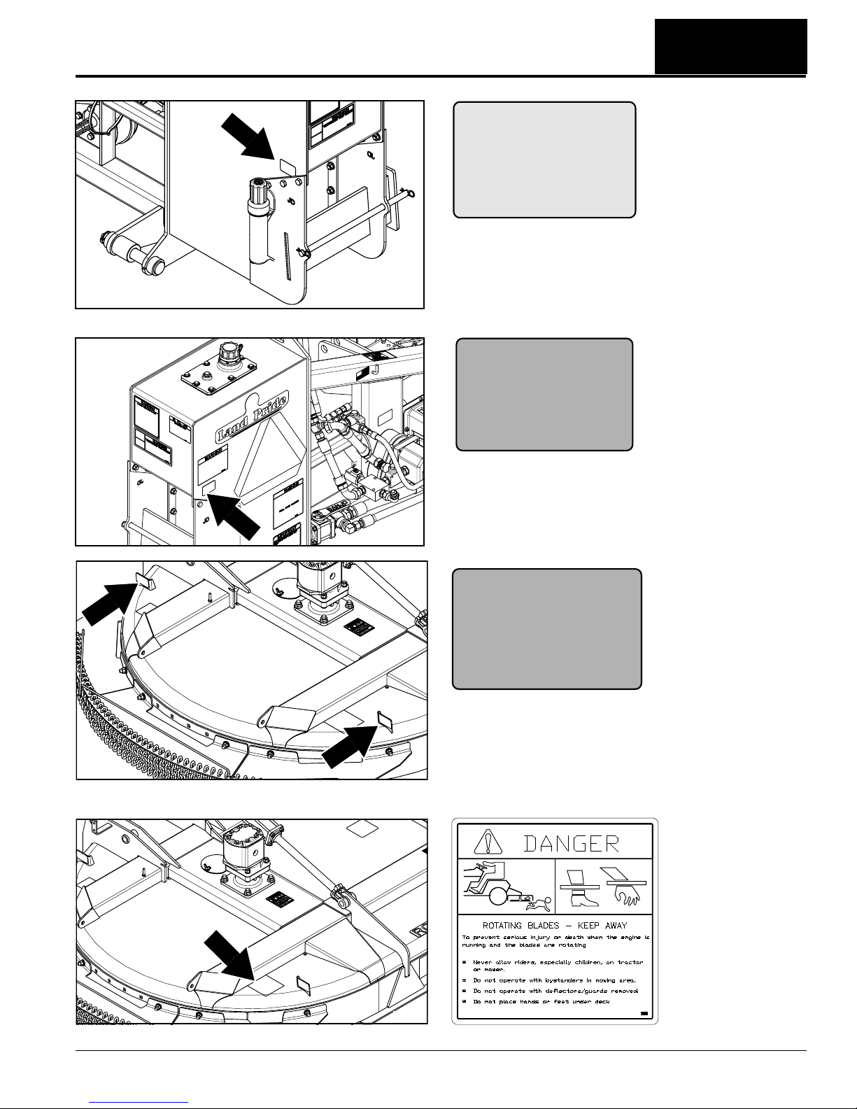
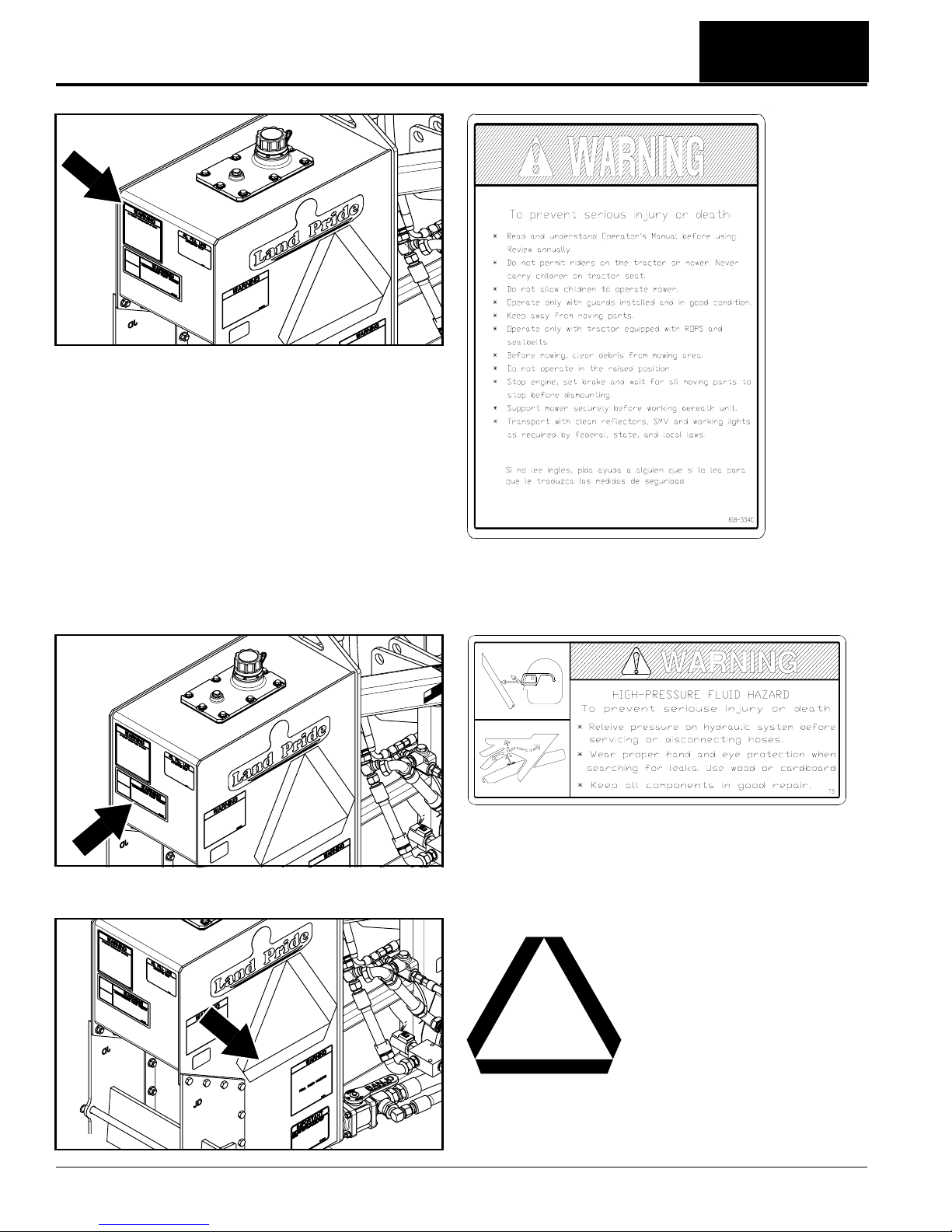
Safety Labels . . . . . . . . . . . . . . . . . . . . . . . . . . . . . 4
Introduction . . . . . . . . . . . . . . . . . . . . . . . . . . 10
Application . . . . . . . . . . . . . . . . . . . . . . . . . . . . . . . 10
Using This Manual . . . . . . . . . . . . . . . . . . . . . . . . . 10
Owner Assistance . . . . . . . . . . . . . . . . . . . . . . . . . 10
Serial Number . . . . . . . . . . . . . . . . . . . . . . . . . . 10
Section 1: Assembly & Set-up . . . . . . . . . . . 12
Tractor Requirements . . . . . . . . . . . . . . . . . . . . . . 12
Protective Equipment Requirements . . . . . . . . . . . 13
Dealer Preparations . . . . . . . . . . . . . . . . . . . . . . . 13
Hooking-up the Rotary Cutter . . . . . . . . . . . . . . . . 14
Driveline Installation . . . . . . . . . . . . . . . . . . . . . . . 15
Check Driveline Collapsible Length . . . . . . . . . . 15
Shorten Driveline . . . . . . . . . . . . . . . . . . . . . . . . 16
Check Driveline Maximum Length . . . . . . . . . . . 16
Check Driveline Interference . . . . . . . . . . . . . . . 16
Hydraulic Reservoir Oil Fill . . . . . . . . . . . . . . . . . . 17
Transport Safety Chain . . . . . . . . . . . . . . . . . . . . . 17
Breakaway Cylinder . . . . . . . . . . . . . . . . . . . . . . . 17
Weight Hanger . . . . . . . . . . . . . . . . . . . . . . . . . . . 18
Gauge Wheels (Optional) . . . . . . . . . . . . . . . . . . . 18
Section 2: Hydraulic Set-up Options . . . . . . 19
Options . . . . . . . . . . . . . . . . . . . . . . . . . . . . . . . . . 19
Tractor Control . . . . . . . . . . . . . . . . . . . . . . . . . . . 19
Hydraulic Hose Hook-up . . . . . . . . . . . . . . . . . . 19
Console Control Lever Functional Checks . . . . . 20
Solenoid Control . . . . . . . . . . . . . . . . . . . . . . . . . . 21
Independent Control . . . . . . . . . . . . . . . . . . . . . . . 22
Solenoid Valve Block Functions . . . . . . . . . . . . . . 22
Independent Control . . . . . . . . . . . . . . . . . . . . . . 22
Solenoid Control . . . . . . . . . . . . . . . . . . . . . . . . . 22
Control Sticks . . . . . . . . . . . . . . . . . . . . . . . . . . . . 23
Control Stick Hook-up . . . . . . . . . . . . . . . . . . . . 24
Control Stick Operation . . . . . . . . . . . . . . . . . . . 25
Control Stick Functional Checks . . . . . . . . . . . . . 25
Section 3: Adjustments . . . . . . . . . . . . . . . . . 28
Hydraulic Flow Control . . . . . . . . . . . . . . . . . . . . . 28
Flow Control Valve on the Rotary Cutter . . . . . . 28
Turtle/Rabbit Flow Control at the Tractor . . . . . . 28
Deck Level Adjustments . . . . . . . . . . . . . . . . . . . . 29
Without Gauge Wheels . . . . . . . . . . . . . . . . . . . 29
With Gauge Wheels . . . . . . . . . . . . . . . . . . . . . . 29
Section 4: Operating Procedures . . . . . . . . . 30
Operating Checklist . . . . . . . . . . . . . . . . . . . . . . . . 30
Transporting . . . . . . . . . . . . . . . . . . . . . . . . . . . . . 30
Basic Operating Instructions . . . . . . . . . . . . . . . . . 31
Breakaway Instructions . . . . . . . . . . . . . . . . . . . . . 32
Shear Bolt Replacement . . . . . . . . . . . . . . . . . . 32
Un-hooking the Rotary Cutter . . . . . . . . . . . . . . . .32
General Operating Instructions . . . . . . . . . . . . . . .33
Section 5: Optional Equipment . . . . . . . . . . . 34
Parallel Arm Rotary Cutter Options . . . . . . . . . . . .34
Weight Hangers . . . . . . . . . . . . . . . . . . . . . . . . . . .35
Operator Protective Shield . . . . . . . . . . . . . . . . . . .36
Section 6: Hydraulic Plumbing . . . . . . . . . . . 37
Breakaway Cylinder . . . . . . . . . . . . . . . . . . . . . . . .37
Pressure Shut Down Valve Operation . . . . . . . .37
Tractor Control . . . . . . . . . . . . . . . . . . . . . . . . . . . .37
Solenoid Control . . . . . . . . . . . . . . . . . . . . . . . . . .38
Solenoid Plumbing . . . . . . . . . . . . . . . . . . . . . . .38
Hydraulic Cylinder Plumbing . . . . . . . . . . . . . . . .38
Deck Motor Plumbing . . . . . . . . . . . . . . . . . . . . .39
Independent Control . . . . . . . . . . . . . . . . . . . . . . .40
Cylinder Pump Plumbing . . . . . . . . . . . . . . . . . .40
Hydraulic Cylinder Plumbing . . . . . . . . . . . . . . . .40
Deck Motor Plumbing . . . . . . . . . . . . . . . . . . . . .41
Section 7: Electrical Wiring Schematics . . . . 42
Solenoid Control Option . . . . . . . . . . . . . . . . . . . . .42
Wiring Schematic Without Gauge Wheels . . . . .42
Wiring Schematic With Gauge Wheels . . . . . . . .43
Independent Control Option . . . . . . . . . . . . . . . . . .44
Wiring Schematic Without Gauge Wheels . . . . .44
Wiring Schematic With Gauge Wheels . . . . . . . .45
Section 8: Maintenance & Lubrication . . . . . 46
Maintenance . . . . . . . . . . . . . . . . . . . . . . . . . . . . .46
Rotary Cutter Blades . . . . . . . . . . . . . . . . . . . . . . .46
Skid Shoes . . . . . . . . . . . . . . . . . . . . . . . . . . . . . .47
Solenoid Valve Block . . . . . . . . . . . . . . . . . . . . . . .48
Hydraulic Hose Replacement . . . . . . . . . . . . . . . .48
Tractor Maintenance . . . . . . . . . . . . . . . . . . . . . . . 49
Storage . . . . . . . . . . . . . . . . . . . . . . . . . . . . . . . . .49
Lubrication Points . . . . . . . . . . . . . . . . . . . . . . . . .50
Parallel Arm . . . . . . . . . . . . . . . . . . . . . . . . . . . .50
Deck Pivot . . . . . . . . . . . . . . . . . . . . . . . . . . . . .50
Parallel Arm Pivot . . . . . . . . . . . . . . . . . . . . . . . . 50
Driveline Yokes . . . . . . . . . . . . . . . . . . . . . . . . . 51
Driveline Profile . . . . . . . . . . . . . . . . . . . . . . . . .51
Gauge Wheel Yoke and Wheel Bearing . . . . . . .51
Ratchet Jack . . . . . . . . . . . . . . . . . . . . . . . . . . . .51
Motor Spindle Hub . . . . . . . . . . . . . . . . . . . . . . . . . 52
Hydraulic Reservoir . . . . . . . . . . . . . . . . . . . . . . . .52
Speed Increaser . . . . . . . . . . . . . . . . . . . . . . . . . .52
Section 9: Specifications & Capacities . . . . . 53
Section 10: Features & Benefits . . . . . . . . . . 55
Section 11: Troubleshooting . . . . . . . . . . . . . 56
Section 12: Torque Values Chart . . . . . . . . . . 58
Section 13: Warranty . . . . . . . . . . . . . . . . . . . 59

1
Important Safety Information
2/03/12 RCP2660, RCPM2660, RCP3060 and RCPM3060 Parallel Arm Rotary Cutter 316-111M
Table of Contents
Important Safety Information
▲
These are common practices that may or may not be applicable to the products described in
this manual.
Safety at All Times
Thoroughly read and understand
the instructions given in this
manual before operation. Refer to
the “Safety Label” section, read
all instructions noted on them.
Do not allow anyone to operate
this equipment who has not fully
read and comprehended this
manual and who has not been
properly trained in the safe
operation of the equipment.
▲Operator should be familiar with
all functions of the unit.
▲Operate implement from the
driver’s seat only.
▲Make sure all guards and shields
are in place and secured before
operating implement.
▲Do not leave tractor or implement
unattended with engine running.
▲Dismounting from a moving
tractor could cause serious injury
or death.
▲Do not allow anyone to stand
between the tractor and
implement while backing up to the
implement.
▲Keep hands, feet, and clothing
away from power-driven parts.
▲Wear snug fitting clothing to avoid
entanglement with moving parts.
▲Watch out for wires, trees, etc.,
when raising implement. Make
sure all persons are clear of
working area.
▲Turning tractor too tight may
cause implement to ride up on
wheels. This could result in injury
or equipment damage.
▲Do not carry passengers on
implement at any time.
Look For The Safety Alert Symbol
The SAFETY ALERT SYMBOL indicates there is a
potential hazard to personal safety involved and extra
safety precaution must be taken. When you see this
symbol, be alert and carefully read the message that
follows it. In addition to design and configuration of
equipment, hazard control and accident prevention
are dependent upon the awareness, concern,
prudence and proper training of personnel involved in
the operation, transport, maintenance and storage of
equipment.
!
Be Aware of
Signal Words
A Signal word designates a degree or
level of hazard seriousness. The
signal words are:
Indicates an imminently hazardous
situation which, if not avoided, will
result in death or serious injury. This
signal word is limited to the most
extreme situations, typically for
machine components that, for
functional purposes, cannot be
guarded.
!DANGER
Indicates a potentially hazardous
situation which, if not avoided, could
result in death or serious injury, and
includes hazards that are exposed
when guards are removed. It may also
be used to alert against unsafe
practices.
Indicates a potentially hazardous
situation which, if not avoided, may
result in minor or moderate injury. It
may also be used to alert against
unsafe practices.
!WARNING
!CAUTION
For Your Protection
▲Thoroughly read and understand
the “Safety Label” section, read all
instructions noted on them.
Shutdown and Storage
▲Lower machine to ground, put
tractor in park, turn off engine, and
remove the key.
▲Detach and store implements in a
area where children normally do
not play. Secure implement by
using blocks and supports.
OFF
REMOVE
Parts Manual QR Locator
The QR (Quick Reference) code on the front
cover and to the left will take you to the
Parts Manual for this equipment. Download
the appropriate App on your smart phone,
open the App, point your phone on the QR
code and take a picture.
Dealer QR Locator
The QR code on the left will
link you to available dealers
for Land Pride products.
Refer to Parts Manual
QR Locator on this page for
detailed instructions.

2
Important Safety Information
RCP2660, RCPM2660, RCP3060 and RCPM3060 Parallel Arm Rotary Cutter 316-111M 2/03/12
Table of Contents
These are common practices that may or may not be applicable to the products described in
this manual.
Transport
Machinery Safely
▲Comply with state and local laws.
▲Maximum transport speed for
implement is 20 mph. DO NOT
EXCEED. Never travel at a speed
which does not allow adequate
control of steering and stopping.
Some rough terrain require a
slower speed.
▲Sudden braking can cause a
towed load to swerve and upset.
Reduce speed if towed load is not
equipped with brakes.
▲Use the following maximum
speed - tow load weight ratios as
a guideline:
20 mph when weight is less
than or equal to the weight of
tractor.
10 mph when weight is double
the weight of tractor.
▲IMPORTANT: Do not tow a load
that is more than double the
weight of tractor.
Use Safety
Lights and Devices
▲Slow moving tractors, self-
propelled equipment, and towed
implements can create a hazard
whendrivenon publicroads.They
are difficult to see, especially at
night.
▲Flashing warning lights and turn
signals are recommended
whenever driving on public roads.
Practice Safe
Maintenance
▲Understand procedure before
doing work. Use proper tools and
equipment, refer to Operator’s
Manual for additional information.
▲Work in a clean dry area.
▲Lower the implement to the
ground, put tractor in park, turn off
engine, and remove key before
performing maintenance.
▲Allow implement to cool
completely.
▲Do not grease or oil implement
while it is in operation.
▲Inspect all parts. Make sure parts
are in good condition & installed
properly.
▲Remove buildup of grease, oil or
debris.
▲Remove all tools and unused
parts from implement before
operation.
Use A Safety Chain
▲A safety chain will help control
drawn machinery should it
separate from the tractor
drawbar.
▲Use a chain with the strength
rating equal to or greater than
the gross weight of the towed
machinery.
▲Attach the chain to the tractor
drawbar support or other
specified anchor location. Allow
only enough slack in the chain
to permit turning.
▲Do not use safety chain for
towing.

3
Important Safety Information
2/03/12 RCP2660, RCPM2660, RCP3060 and RCPM3060 Parallel Arm Rotary Cutter 316-111M
Table of Contents
These are common practices that may or may not be applicable to the products described in
this manual.
Prepare for Emergencies
▲Be prepared if a fire starts.
▲Keep a first aid kit and fire
extinguisher handy.
▲Keep emergency numbers for
doctor, ambulance, hospital and
fire department near phone.
911
Keep Riders
Off Machinery
▲Riders obstruct the operator’s
view, they could be struck by
foreign objects or thrown from the
machine.
▲Never allow children to operate
equipment.
Avoid High
Pressure Fluids Hazard
▲Escapingfluidunder pressure can
penetrate the skin causing
serious injury.
▲Avoid the hazard by relieving
pressure before disconnecting
hydraulic lines or performing work
on the system.
▲Make sure all hydraulic fluid
connections are tight and all
hydraulic hoses and lines are in
good condition before applying
pressure to the system.
▲Use a piece of paper or
cardboard, NOT BODY PARTS, to
check for suspected leaks.
▲Wear protective gloves and safety
glasses or goggles when working
with hydraulic systems.
▲If an accident occurs, see a
doctor immediately. Any fluid
injected into the skin must be
treated within a few hours or
gangrene may result.
Wear
Protective Equipment
▲Wear protective clothing and
equipment appropriate for the job.
Avoid loose fitting clothing.
▲Prolonged exposure to loud noise
can cause hearing impairment or
hearing loss. Wear suitable
hearing protection such as
earmuffs or earplugs.
▲Operating equipment safely
requires the full attention of the
operator. Avoid wearing radio
headphones while operating
machinery.
Tire Safety
▲Tire changing can be dangerous
and should be preformed by
trained personnel using the
correct tools and equipment.
▲When inflating tires, use a clip-on
chuck and extension hose long
enough to allow you to stand to
one side and NOT in front of or
over the tire assembly. Use a
safety cage if available.
▲When removing and installing
wheels, use wheel handling
equipment adequate for the
weight involved.
Use Seat Belt and ROPS
▲Operate only tractors equipped
with Roll-Over Protective
Structure (ROPS) and seat belt.
▲Fasten seat belt snugly and
securely to help protect operator
from being thrown, crushed, or
severely injured if a rollover
occurs; and from falling off the
tractor and being ran over by the
tractor and/or cutter. Not using the
seat belt can result in serious
injury or death.
▲Wearing protective equipment
such as safety shoes, safety
glasses, hard hat, and ear plugs
is highly recommended.

4
Important Safety Information
RCP2660, RCPM2660, RCP3060 and RCPM3060 Parallel Arm Rotary Cutter 316-111M 2/03/12
Table of Contents
818-045C
Warning - Pinch Point Hazard
2-Places
Safety Labels
1. YourRotary Cuttercomes equippedwithallsafetylabelsin
place. They were designed to help you safely operate your
implement. Read and follow their directions.
2. Keep all safety labels clean and legible.
3. Replace all damaged or missing labels. To order new
labels go to your Land Pride dealer.
4. Some new equipment installed during repair requires
safety labels to be affixed to the replaced component as
specified by Land Pride. When ordering new components
make sure the correct safety labels are included in the
request. To order new labels go to your Land Pride dealer.
5. Refer to this section for proper label placement.
To install new labels:
a. Clean the area the label is to be placed.
b. Spray soapy water on the surface where the label is to
be placed.
c. Peel backing from label. Press firmly onto the surface.
d. Squeeze out air bubbles with the edge of a credit card.
22057
818-142C
Danger - Rotating Driveline Hazard
22058
838-368C
Warning - Pinch Point Hazard
26694

5
Important Safety Information
2/03/12 RCP2660, RCPM2660, RCP3060 and RCPM3060 Parallel Arm Rotary Cutter 316-111M
Table of Contents
30031
818-230C
Red Reflector (2 places)
818-564C
Danger - Keep Away
Rotating Blade Hazard
22007
22007
818-229C
Amber Reflector
818-230C
Red Reflector
30032

6
Important Safety Information
RCP2660, RCPM2660, RCP3060 and RCPM3060 Parallel Arm Rotary Cutter 316-111M 2/03/12
Table of Contents
22006
22006
818-555C
Danger - Rotating
Blades Keep Away
818-830C
Warning/Danger/Notice - Combination Safety Decal
818-556C
Danger - Thrown Object
Hazard (3-Places)
22006

7
Important Safety Information
2/03/12 RCP2660, RCPM2660, RCP3060 and RCPM3060 Parallel Arm Rotary Cutter 316-111M
Table of Contents
818-391C
Warning - Tractor Roll
Over Hazard
818-390C
Warning - Thrown
Object Hazard
22007
818-339C
Warning - High Pressure
Fluid Hazard
30032
30032

8
Important Safety Information
RCP2660, RCPM2660, RCP3060 and RCPM3060 Parallel Arm Rotary Cutter 316-111M 2/03/12
Table of Contents
818-003C
Slow Moving Vehicle Emblem
818-554C
Caution - General Safety Information
818-831C
Warning - High Pressure Fluid Hazard
30032
30032
30032

9
Important Safety Information
2/03/12 RCP2660, RCPM2660, RCP3060 and RCPM3060 Parallel Arm Rotary Cutter 316-111M
Table of Contents
848-369C
Caution: Avoid Injury or Machine Damage
818-240C
(Used only on RCPM2660 & RCPM3060 Series)
Important - Operate only with 1000 rpm PTO
818-388C
Important - Valve must be open
818-403C
(Used only on RCP2660 & RCP3060 Series)
Caution - Operate only with 540 rpm PTO
30032
12324
30033
12324

10
Introduction
RCP2660, RCPM2660, RCP3060 and RCPM3060 Parallel Arm Rotary Cutter 316-111M 2/03/12
Table of Contents
Terminology
“Right” or “Left” as used in this manual is determined by
facing the direction the machine will operate while in use
unless otherwise stated.
Definitions
Owner Assistance
The Warranty Registration card should be filled out by
the dealer at the time of purchase. This information is
necessary to provide you with quality customer service.
If customer service or repair parts are required contact a
LandPride dealer.A dealer hastrainedpersonnel,repair
parts and equipment needed to service the cutter.
The parts on your cutter have been specially designed
and should only be replaced with genuine Land Pride
parts. Therefore, should your cutter require replacement
parts go to your Land Pride Dealer.
Serial Number
Model No. _____________Serial No. _______________
For quick reference and prompt service, record model
number and serial number in the spaces provided above
and again on warranty page 59. Always provide model
number and serial number when ordering parts and in all
correspondences with your Land Pride dealer. Refer to
Figure 1 for location of your serial number plate.
Serial Number Plate Location
Figure 1
IMPORTANT: A special point of information related
to the following topic. Land Pride’s intention is this
information must be read & noted before continuing.
NOTE: A special point of information that the
operator should be aware of before continuing.
30033
Introduction
Land Pride welcomes you to the growing family of new
product owners.
ThisRotary Cutterhasbeen designedwith care andbuilt
by skilled workers using quality materials. Proper
assembly, maintenance and safe operating practices will
help you get years of satisfactory use from the machine.
Application
The Hydraulic Parallel Arm Rotary Cutters are designed
and built by Land Pride to provide excellent cutting
performance on ditch banks and other sloping areas
adjacent to right-of-ways, lakes, ponds and streams.
They are designed to work equally as well in and around
areas of restricted access such as over or under fences,
guardrails, low overhanging branches, tree limbs and
hedges. These units perform extremely well in tall grass
cutting applications and will easily cut through standing
brush up to two inches in diameter. An optional cutter
head equipped with two forward and one rear gauge
wheel is also available for customers who want to
maintain a constant cutting height with minimal control
lever manipulation.
The RCP2660 and RCPM2660 cutters are adapted for
Category 2 or 3 three-point hitch mounting on 75 hp. to
150 hp. tractors weighing 8,000 lbs. or more.
The RCP3060 and RCPM3060 cutters are adapted for
Category 2 or 3 three-point hitch mounting on 95 hp. to
175 hp. tractors weighing 12,000 lbs. or more.
The Hydraulic drive requires 540 rpm input PTO speed
for RCP2660 & RCP3060 models and 1000 rpm for
RCPM2660 & RCPM3060 models. Depending upon
hydraulic configuration, one, two or four duplex hydraulic
outlets are required on the tractor to operate the cutter’s
parallel arms and deck angle.
See “Specifications & Capacities” on page 53
and “Features & Benefits” on page 55 for additional
information and performance enhancing options.
Using This Manual
•This Operator’s Manual is designed to help familiarize
you with safety, assembly, operation, adjustments,
troubleshooting, and maintenance. Read this manual
and follow the recommendations to help ensure safe
and efficient operation.
•The information contained within this manual was
current at the time of printing. Some parts may change
slightly to assure you of the best performance.
•To order a new Operator’s or Parts Manual contact
your authorized dealer. Manuals can also be
downloaded, free-of-charge from our website at
www.landpride.com.

11
Introduction
2/03/12 RCP2660, RCPM2660, RCP3060 and RCPM3060 Parallel Arm Rotary Cutter 316-111M
Table of Contents
Further Assistance
Your dealer wants you to be satisfied with your new
cutter.Ifforanyreason youdonotunderstandanypartof
thismanual or arenot satisfiedwith theservice received,
the following actions are suggested:
1. Discuss the matter with your dealership service
manager making sure he is aware of any problems
you may have and that he has had the opportunity to
assist you.
2. If you are still not satisfied, seek out the owner or
general manager of the dealership, explain the
problem and request assistance.
3. For further assistance write to:
Land Pride Service Department
1525 East North Street
P.O. Box 5060
Salina, Ks. 67402-5060
E-mail address
lpser[email protected]

12
Section 1: Assembly & Set-up
RCP2660, RCPM2660, RCP3060 and RCPM3060 Parallel Arm Rotary Cutter 316-111M 2/03/12
Table of Contents
Section 1: Assembly & Set-up
The front gauge wheel and mount may interfere with the
right reartractor tirewhen deckisfoldedfortransporting.
This is especially true if the outside face of the tire is
more than 47" away from the tractor center. Tractors
equipped with dual wheels may need the outside right
rear wheel removed. The RCP(M)3060 cutter requires a
dual wheel on the left hand side or wheel weights equal
to the weight of a dual wheel.
RCP2660 & RCPM2660 Minimum Tractor Requirements
Figure 1-1
RCP3060 & RCPM3060 Minimum Tractor Requirements
Figure 1-2
12250
TRACTOR CAB OR
ROLL OVER
PROTECTIVE STRUCTURE
OPERATOR
PROTECTIVE
SHIELD
8,000 LBS. MIM.
24583
TRACTOR CAB OR
ROLL OVER
PROTECTIVE STRUCTURE
OPERATOR
PROTECTIVE
SHIELD
REQUIRED
LEFT HAND DUAL
OR LEFT HAND
WHEEL WEIGHTS
12,000 LBS. MIM.
Tractor Requirements
Horsepower
Tractor horsepower must be capable of controlling the
Parallel Arm Rotary Cutter under all operating
conditions. Smaller tractors must not be used.
RCP2660 & RCPM2660
Horsepower Range . . . . . . . . . . . . . . . . . .75-150 HP
RCP3060 & RCPM3060
Horsepower Range . . . . . . . . . . . . . . . . . .95-175 HP
Weight
Absolute Minimum: Tractor weight must be sufficient to
controltheParallelArmRotaryCutter under all operating
conditions. Tractors not meeting the absolute minimum
weight listed below must not be used.
Basic Minimum: A right hand overturning torque load is
present on the tractor when parallel arms are fully
extended. Tractors will need auxiliary counterbalance
weights added if the tractor’s total weight is less than the
basic minimum weight listed below.
It is best to add auxiliary weights to the left rear tractor
wheel. In addition, up to eight 100 lb. suitcase type
weights can be added to the optional weight hanger on
the hydraulic reservoir. However, adding weights to the
reservoir can lighten the tractor’s front end.
RCP2660 & RCPM2660
Tractor absolute minimum weight. . . . . . . . 8,000 lbs.
Tractor basic minimum weight. . . . . . . . . . 8,500 lbs.
RCP3060 & RCPM3060
Tractor absolute minimum weight. . . . . . . 12,000 lbs.
Tractor basic minimum weight. . . . . . . . . 13,500 lbs.
!WARNING
Front tractor weights and/or ballast to tires may be required
to offset weight of cutter and auxiliary weights. Consult your
tractor manual to determine if additional ballast is needed.
Wheel Base
Refer to Figure 1-1 & Figure 1-2:
Rear wheel base must meet minimum requirements
when measured from outside face to outside face of rear
tractor tires. Smaller wheel bases must not be used.
RCP2660 & RCPM2660
Rear Wheel Base. . . . . . . . . . . . . . . . . .74" minimum
RCP3060 & RCPM3060
Rear Wheel Base . . . . . . . . . . . . . . . . .95" minimum
IMPORTANT: Extended parallel arms will pull the
tractor’s front to the right. When necessary, add
weight to the tractor front to stabilize it. Consult your
tractor’s manual for allowable added weights.
IMPORTANT: The tractor’s right rear wheel should
be pressurized to the manufactures highest
recommended air pressure.

13
Section 1: Assembly & Set-up
2/03/12 RCP2660, RCPM2660, RCP3060 and RCPM3060 Parallel Arm Rotary Cutter 316-111M
Table of Contents
Hitch
A 3-Point Category II or Category III hitch is required.
The lower 3-Point arms of the 3-Point hitch must be
stabilized to prevent side-to-side movement. Most
tractors have sway blocks or adjustable chains for this
purpose.
Hydraulic Outlets
Thenumberoftractorhydraulicduplexoutletsrequiredis
dependent upon how the Rotary Cutter is set-up.
Independent Control:
One duplex outlet is required to operate the breakaway
cylinder. APTOdrivenpumpon theunit pumpshydraulic
fluid from the reservoir to the parallel arm cylinders and
deck pivot cylinder. The cylinders aresolenoid activated
withmomentary push button switchesat thecontrol stick.
Solenoid Control:
Two duplex outlets are required. One duplex outlet is
required to operate the breakaway cylinder. The second
duplex outlet operates the parallel arm cylinders and
deck pivot cylinder. The cylinders aresolenoid activated
withmomentarypushbuttonswitchesatthecontrolstick.
The second duplex outlet must be capable of continuous
hydraulic fluid flow.
Tractor Control:
Four duplex outlets are required to operate the parallel
arm cylinders, deck pivot cylinder and breakaway
cylinder. Each cylinder is connected to a duplex outlet
and activated with tractor control levers. Each duplex
outlet must be capable of infinite variable flow control
(turtle/rabbit control) with center detent “OFF” levers.If
gauge wheels are included, “ARM 2” and “Deck Pivot”
levers must be capable of being placed in float position.
PTO Speed
TheRCPcuttersrequires540rpmPowerTake-Off(PTO)
speed and the RCPM cutter requires 1000 rpm PTO
speed to operate the hydraulic pump(s) & motor.
Required tractor horsepower to operate the pump(s) and
motor is approximately 30 HP.
Protective Equipment Requirements
Refer to Figure 1-1:
The tractor MUST be equipped with protective
equipment designed to shield the operator from thrown
objects and tractor rollover. An enclosed tractor cab with
a Roll Over Protective Structure (ROPS) may qualify.
See the tractor’s manual to see if it qualifies.
Tractors with only a ROPS must have a protective shield
added to the right hand fender. A universal operator
protective shield is available from Land Pride. Refer to
page 36 for additional information and installation.
It is also recommended that a protective shield or screen
be added to the right hand side of the tractor engine
cowling and radiator. This will help protect the tractor’s
finish and radiator against thrown objects.
Dealer Preparations
This cutter has been assembled at the factory. However,
some preparations will be necessary to attach the cutter
to customer’s tractor.
•Make certain the intended tractor conforms to the
“Tractor Requirements” on page 12.
•Review and check off Preparation Checklist below
before proceeding.
Preparation Checklist
Upper hitch pin is not Included with unit. Determine
customer’s tractor hitch type. (Cat II or Cat III). Buy
required upper hitch pin locally or order a Land Pride
hitch pin if customer’s tractor does not included the pin.
See Land Pride’s upper hitch pin part numbers below.
805-079C - Upper Hitch Pin Cat II (1" dia. x 3 3/8" usable)
805-196C - Upper Hitch Pin Cat III (1 1/4" dia. x 3 3/8" usable)
Before operating this unit, 80-90 EP Gear Lube must
be added to the gearbox & motor as indicated in the
“Maintenance & Lubrication” section for “Speed
Increaser” on page 52 of this manual.
35 Gallons of Hydraulic Fluid is needed for the
hydraulic reservoir. Use any high quality mineral based
hydraulic fluid such as Mobil Fluid 424 with a viscosity
rating of 10W-30.
Additional hydraulic fluid (approx 2 gallons) for the
tractor reservoir.
Miscellaneous assembly tools: hammer, tape measure,
assortment of wrenches and sockets, and spirit level.
Quick disconnect adaptors that match tractor’s duplex
outlets. Quantity required depends on option selected:
(4) If equipped with solenoid control box.
(8) If not equipped with hose hook-up.
Possible need for forklift or hoist capable of lifting 2500
lbs.
Auxiliary tractor weights (depending on tractor size).
See “Tractor Requirements” on page 12.
A minimum of two people available during assembly.
If a pin, bolt or other part has been removed, and you
are unsure where it is used, use the Parts Manual to
identify it. Be sure the part gets used in the correct
location. By double checking while you assemble, you
will lessen the chance of using a bolt incorrectly that
may be needed later.
Safety decals are legible and undamaged from
shipment.
PTO driveline and loose parts bag/box shipped with
the cutter are present.

14
Section 1: Assembly & Set-up
RCP2660, RCPM2660, RCP3060 and RCPM3060 Parallel Arm Rotary Cutter 316-111M 2/03/12
Table of Contents
The following set-up instructions are standard for all
options. They should be completed before continuing
with optional set-up instructions.
Hooking-up the Rotary Cutter
!DANGER
A Crushing Hazard exists when hooking-up equipment to a
tractor. Do not allow anyone to stand between tractor and
implement while backing-up to implement. Do not operate
hydraulic 3-Point lift controls while someone is directly
behind the tractor or near the implement.
Prepare cutter as follows:
1. Be sure transport safety chain is hooked to the deck.
See Figure 1-9 on page 17.
2. Position cutter on a flat level concrete surface.
Refer to Figure 1-3:
3. There are three hitch categories represented in
Figure 1-3. Determine which category fits the tractor
being used and arrange cutter hitch pins as shown
for that category.
Refer to Figure 1-4:
4. Slowly back tractor up to the Rotary Cutter while
using tractor’s 3-point hydraulic controls to align
lower hitch link holes with clevis holes on the cutter.
5. Place tractor gear selector in park and/or set brakes,
shut engine off and remove ignition key.
6. Aligned and positioned tractor’s lower hitch holes in
the clevises. Attach the lower arms to the clevises
with hitch pins and secure with linch pins.
7. Adjusttopcenterlinkinorouttoaligncenterlinkhole
with the cutter’s center hitch pin hole. Connect top
center link to cutter hitch pin hole using customer
supplied clevis pin and linch pin.
8. Make certain the lower 3-point arms are stabilized to
prevent excessive side movement.
9. Returntotractorandslowlyraisetractor3-Pointhitch
about 1 to 2 inches. Stow jack stands in the raised
position.
10. Slowlyoperatetractor's3-Point arms upanddownto
check clearance between cutter components and
tractorcomponents.Move orremovetractordrawbar
if it interferes with cutter.
11. Adjust tractor's lower arms to level cutter frame from
left to right.
IMPORTANT: Hydraulic fluid must be added to the
cutterhydraulicreservoirbefore operatingthepump.
Otherwise, the hydraulic pump will be damaged.
NOTE: Driveline installation instructions will follow
after hooking-up cutter to a tractor. This is because
the distance between tractor PTO shaft and speed
increaser input shaft can vary from tractor to tractor.
Hitch Pin Configuration (Based on Hitch Category)
Figure 1-3
Tractor 3-Point Hitch
Figure 1-4
12. Adjust center top-link to level cutter frame from front
to rear.
13. Final deck leveling adjustments will be made later.
Category II Quick HItch
Category III 3-Point Hitch
Category II 3-Point Hitch 24642
23998

15
Section 1: Assembly & Set-up
2/03/12 RCP2660, RCPM2660, RCP3060 and RCPM3060 Parallel Arm Rotary Cutter 316-111M
Table of Contents
Driveline Installation
!DANGER
Do not engage tractor PTO while hooking-up and unhooking
driveline or while someone is standing near the driveline. A
person’s body and/or clothing can become entangled in the
driveline resulting in serious injury or death.
!DANGER
All guards and shields must be installed and in good working
condition at all times during cutter operation!
!WARNING
Always disengage PTO, engage parking brake, shut tractor
engine off, remove switch key, and wait for blades to come to
a complete stop before dismounting tractor.
!WARNING
Do not over-speed PTO or machine breakage may result.
Some tractors are equipped with multispeed PTO ranges. Be
certain your tractor’s PTO is set for the cutter’s rated PTO
speed. See Specifications & Capacities for rated PTO speed.
Refer to Figure 1-5:
1. Start tractor and slowly engage 3-point controls to
move lower arms until the PTO shaft for the speed
increaser is aligned and level with tractor PTO shaft.
Securely block cutter in this position.
2. Place tractor gear selector in park, shut tractor
engine off, set park brake and remove switch key.
3. Slide inner yoke of driveline over speed increaser
shaft and secure with locking collar.
4. Slide outer yoke of driveline over tractor PTO shaft
and secure with locking collar.
5. Push and pull on driveline yokes to be certain they
IMPORTANT: Do not engage tractor PTO until
driveline is fully connected and hydraulic fluid has
been added to the cutter reservoir.
IMPORTANT: A quick hitch may be used, but is not
recommended because it moves the cutter deck
back about 5" and impedes operator visibility.
IMPORTANT: An additional driveline may be
required if cutter is to be used on more than one
tractor, especially if a Quick Hitch is used.
The driveline must be lubricated before putting it into
service. Refer to “Lubrication Points” on page 50.
The tractor’s PTO shaft and cutter gearbox shaft
must be aligned and level with each other during
installation of driveline.
are securely fastened to the speed increaser and
PTO shafts.
6. If driveline yoke will not lock in place, skip to “Check
Driveline Collapsible Length” below.
7. Attach safety chain on the inner driveline shield to
the parallel arm frame. Re-latch safety chain to the
inner driveline shield.
8. Attach safety chain on the outer driveline shield to
the tractor frame. Re-latch safety chain to the outer
driveline shield.
9. Continue with “Check Driveline Collapsible
Length” below.
Check Driveline Collapsible Length
1. Make sure driveline is properly installed and level
beforecheckingdrivelinecollapsiblelength.(Referto
"Driveline Installation" instructions on page 15.)
Refer to Figure 1-5:
2. With driveline level, measure (“B” dimension) back
from universal joint shield to end of outer driveline
shield as shown in Figure 1-5.
3. If measurement is 1" or more, skip to “Check
Driveline Maximum Length” on page 16. If
measurement is less than 1", shorten driveline using
instructions provided under “Shorten Driveline” on
page 16.
Shortening PTO Driveline Shields & Shafts
Figure 1-5
IMPORTANT: Two small chains are supplied with
the driveline. To keep driveline shields from rotating,
thesechainsmustbeattached to theouterandinner
driveline shields and to the cutter and tractor.
IMPORTANT: Adrivelinethat is too long can bottom
out causing structural damage to tractor and cutter.
Alwayscheckdrivelinecollapsedlengthduringinitial
setup, when connecting to a different tractor, and
when alternating between using a quick hitch and a
standard 3-Point hitch. More than one driveline may
be required to fit all applications.
22009

16
Section 1: Assembly & Set-up
2/03/12 RCP2660, RCPM2660, RCP3060 and RCPM3060 Parallel Arm Rotary Cutter 316-111M
Table of Contents
Shorten Driveline
Refer to Figure 1-5:
Be sure to check driveline collapsed length first. If
required, shorten driveline as follows:
1. Un-hook driveline and safety chain from tractor PTO
shaft. Pull outer and inner drivelines apart.
2. Reattach outer driveline to tractor PTO shaft. Pull on
inner and outer driveline yokes to be sure universal
joints are properly secured.
3. Hold inner and outer drivelines parallelto each other:
a. Measure 1" (“B” dimension) back from outer
drivelineuniversaljointshieldandmakeamarkat
this location on the inner driveline shield.
b. Measure 1" (“B” dimension) back from the inner
drivelineuniversaljointshieldandmakeamark at
this location on the outer driveline shield.
4. Remove driveline from tractor PTO shaft and speed
increaser shaft.
5. Measure from end of inner shield to scribed mark
(“X”dimension).Cutoff inner shieldatthemark.Cut
same amount off the inner shaft (“X1” dimension).
6. Measure from end of outer shield to scribed mark
(“Y”dimension).Cutoffoutershieldatthemark.Cut
same amount off the outer shaft (“Y1” dimension).
7. Remove all burrs and cuttings.
8. Continuewith“CheckDriveline MaximumLength”.
Check Driveline Maximum Length
Refer to Figure 1-6:
Thedrivelinemaximumallowablelengthmust,whenfully
extended,have aminimumoverlapofprofiletubesbynot
less than 1/2 the free length with both inner and outer
profile tubes being of equal length.
1. Apply multi-purpose grease to the inside of the outer
shaft and reassemble the driveline.
2. Assemble the two driveline profiles together with just
1/2 overlapping of the profile tubes as shown. Once
assembled,measureandrecordmaximumallowable
length here. ________
3. Continue with “Check Driveline Interference”.
Driveline Maximum Extended Length
Figure 1-6
24804
Outer Shielding has been removed for clarity.
Check Driveline Interference
1. Make certain driveline yokes and safety chains are
properly attached. See steps 7 -9 on page 15.
2. StarttractorandraiseParallelArmRotaryCutterjust
enough to remove support blocks from under the
cutter.
3. Slowly engage tractor hydraulic 3-Point control lever
to lower cutter while checking for sufficient drawbar
clearance. Move drawbar ahead, aside or remove if
required.
Refer to Figure 1-7:
4. With PTO off, raise implement fully up to make the
following checks below. If driveline exceeds any of
the limits listed, set tractor 3-Point lift limiter at a
height that will keep the driveline within its lift limits
and to avoid premature driveline breakdown.
•Driveline does not exceed 25oup.
•Driveline does not exceed maximum allowable
length recorded in step 2 under “Check Driveline
Maximum Length”.
Maximum PTO Driveline Movement During Operation
Figure 1-7
IMPORTANT: Avoid premature driveline
breakdown. A driveline that is operating must not
exceed an angle of 25 degrees up or down while
operating 3-Point lift.
24872

17
Section 1: Assembly & Set-up
2/03/12 RCP2660, RCPM2660, RCP3060 and RCPM3060 Parallel Arm Rotary Cutter 316-111M
Table of Contents
Hydraulic Reservoir Oil Fill
Refer to Figure 1-8:
The Rotary Cutter is shipped without hydraulic fluid.
1. Park cutter on a level surface, set park brake, turn off
ignition switch and remove switch key.
2. Remove fill cap and dipstick from reservoir and add
35 gallons of Mobil 424 to the hydraulic reservoir.
Use care to ensure that dust or other foreign
particles do not contaminate the fluid.
3. Wipe dipstick clean. Fully insert it and remove.
Check oil level on dipstick. Fill with recommended oil
to the full mark. Replace fill cap and dipstick.
Transport Safety Chain
Refer to Figure 1-8 &Figure 1-9:
!WARNING
Transport safety chain must remain hooked to the deck until
ready to extend parallel arms and deck cylinder. Float Switch
must be “OFF” until gauge wheels are resting on the ground.
The transport safety chain should always be hooked to
the deck hook when cutter is folded up. Otherwise, the
operating levers and/or push button switches could be
bumped or hoses could burst allowing deck to fall and
cause damage to cutter, tractor, and anyone nearby.
When unhooking the transport safety chain, make sure
the arm and deck cylinders are retracted and if available,
theFloat Switch issetto “OFF”.Donot forcesafetychain
off the deck hook. If safety chain does not removeeasily,
investigate the problem and correct before continuing.
Once unhooked, store safety chain on the storage hook.
Breakaway Cylinder
Refer to Figure 1-10 on page 17:
The breakaway cylinder protects the Rotary Cutter from
damagewhencutterdeckorparallelarm contacts a solid
objectwhilemovingforward.Itdoesnotprotectthecutter
while backing up. Always make certain the area behind
the cutter is clear before backing up. See Breakaway
Cylinder on page 37 for additional information.
1. Remove 1/2" shipping bolt from cutter before
connecting hydraulic hoses. DO NOT reinstall
shipping bolt.
2. Attach breakaway hoses to a single duplex outlet on
the tractor as shown in Figure 1-10.
IMPORTANT: Any high quality mineral based
hydraulic fluid such as Mobil fluid 424 with a
viscosity rating of 10W-30 is acceptable. See
www.mobil.com for alternate fluids.
IMPORTANT: A 1/2" bolt is installed for shipping
purposes only. This bolt must be remove before
connecting hydraulic hoses to the tractor.
Transport Safety Chain Shown in Storage Position
Figure 1-8
Transport Safety Chain Shown Hooked for Transport
Figure 1-9
Breakaway Cylinder Hose Connections
Figure 1-10
12443
Transport Safety Chain
Storage Hook
Fill Cap With Dip Stick
Drain Plug
22031
Deck Hook
Transport Safety Chain
12256
Important:
LocateandRemove
1/2" Shipping Bolt
Before Connecting
Hydraulic Hoses.

18
Section 1: Assembly & Set-up
RCP2660, RCPM2660, RCP3060 and RCPM3060 Parallel Arm Rotary Cutter 316-111M 2/03/12
Table of Contents
Weight Hanger
Refer to Figure 1-11:
There are five different weight hangers that can be
attached to the reservoir. One of the five must be
installed for operation. See Weight Hangers on page 35
for detailed description of all hangers available.
1. Attach weight hanger (#1) to reservoir with fourteen
1/2"-13 x 1 1/4" GR5 cap screws (#3) and hex flange
locknuts(#3).Tighten locknutsto the correct torque.
2. Attach manual storage container (#9) to the front
side of the reservoir with two 1/4"-20 x 1 1/4" GR5
cap screws (#4), flat washers (#7) and hex nylock
nuts (#6). Tighten nylock nuts to the correct torque.
3. Insert weight retainer pin (#2) through holes in
weight hanger and secure with hairpin cotters (#8).
Weight Hanger Installation
Figure 1-11
Gauge Wheels (Optional)
Refer to Figure 1-12:
The deck with gauge wheels is shipped from the factory
completely assembled to the parallel arm with the
exception of installing the rear ratchet jack and one
gauge wheel.
NOTE: Case/International Harvest weight hanger
includes an L-shaped spacer. Be sure to locate this
spacer between the weight hanger side plate and
hydraulic reservoir tank in assembly.
30029
Case/International Harvest Weight Hanger Only:
Locate L-shaped spacer between weight hanger
side plate and hydraulic reservoir.
Ratchet Jack Installation
1. Check 5/8" hex flange lock nuts securing bolts (#3).
They should be drawn up snug, not tight.
A-frame (#2) should pivot freely on the two bolts.
2. Cutties securing A-frame(#2)and rotateframeback
to position it behind the deck as shown.
3. Attach ratchet jack (#8) to the cutter deck with 1" dia.
clevis pins (#6). Secure clevis pins with hairpin
cotters (#3).
4. Insert long handle in the rear ratchet jack and short
handle in the front ratchet jack. Secure handles with
cotter pins. Bend cotter pin legs to keep pins from
falling out.
Gauge Wheel Installation
1. Install 1 1/4" I.D. machine washer (#4) over yoke
spindle (#1) as shown.
2. Insert yoke spindle (#1) into the front support frame.
3. Install second 1 1/4" I.D. machine washer (#4) over
yoke spindle (#1).
4. Secure yoke spindle to frame with 5/16" dia. roll
pin (#7).
Gauge Wheel Installation
Figure 1-12
NOTE: Installation of gauge wheel and ratchet jack
iseasier afterthe deck hasbeen lowered.Therefore,
it is best to install them just before making “Float
Positioning Control Check” on page 20 for Tractor
Control or just before making “Float Switch ON/OF
Push Button Check” on page 27 for Solenoid and
Independent Control.
NOTE: After deck cutting height is set, it is
recommended that the ratchet jack handles be
removed and stored with the tractor and cutter to
protect the deck finish.
24617
Other manuals for RCP2660
1
This manual suits for next models
3
Table of contents
Other Land Pride Brush Cutter manuals

Land Pride
Land Pride RCR26 series User manual

Land Pride
Land Pride RC45180 User manual

Land Pride
Land Pride RCR2660 User manual

Land Pride
Land Pride RCR1542 User manual

Land Pride
Land Pride SC2672 User manual

Land Pride
Land Pride RCR3515 User manual

Land Pride
Land Pride RCR2560 User manual

Land Pride
Land Pride RC5510 User manual

Land Pride
Land Pride RC5515 User manual

Land Pride
Land Pride RCR3510 User manual