Land Pride SC2672 User manual

Cover photo may show optional equipment
not supplied with standard unit.
Read the Operator’s Manual entirely. When you
see this symbol, the subsequent instructions and
warnings are serious - follow without exception.
Your life and the lives of others depend on it!
!
© Copyright 2012 Printed
Table of Contents
SC2660 & SC2672 Skid Steer
Rotary Cutter
326-025M
24538
Operator’s Manual
4/24/12

SC2660 & SC2672 Skid Steer Rotary Cutter 326-025M 4/24/12
Table of Contents
©Copyright 2012 All rights Reserved
Land Pride provides this publication “as is” without warranty of any kind, either expressed or implied. While every precaution has been taken in the
preparationofthismanual,Land Prideassumes noresponsibilityforerrorsoromissions.Neitheris anyliabilityassumedfordamagesresultingfrom theuse
ofthe information containedherein. Land Pride reservesthe right toreviseand improveits productsas it sees fit.This publicationdescribesthestate of this
product at the time of its publication, and may not reflect the product in the future.
Land Pride is a registered trademark.
All other brands and product names are trademarks or registered trademarks of their respective holders.
Printed in the United States of America.
Important Safety Information . . . . . . . . . . . . . 1
Safety at All Times . . . . . . . . . . . . . . . . . . . . . . . . . 1
Look For The Safety Alert Symbol . . . . . . . . . . . . .1
Safety Labels . . . . . . . . . . . . . . . . . . . . . . . . . . . . . 4
Introduction . . . . . . . . . . . . . . . . . . . . . . . . . . . 7
Application . . . . . . . . . . . . . . . . . . . . . . . . . . . . . . . . 7
Using This Manual . . . . . . . . . . . . . . . . . . . . . . . . . . 7
Terminology . . . . . . . . . . . . . . . . . . . . . . . . . . . . . 7
Definitions . . . . . . . . . . . . . . . . . . . . . . . . . . . . . . 7
Owner Assistance . . . . . . . . . . . . . . . . . . . . . . . . . . 8
Serial Number . . . . . . . . . . . . . . . . . . . . . . . . . . . 8
Further Assistance . . . . . . . . . . . . . . . . . . . . . . . . 8
Section 1: Assembly & Set-up . . . . . . . . . . . . 9
Skid Steer Requirements . . . . . . . . . . . . . . . . . . . . . 9
Dealer Preparations . . . . . . . . . . . . . . . . . . . . . . . . 9
Pre-Assembly Checklist . . . . . . . . . . . . . . . . . . . . . 9
Uncrating . . . . . . . . . . . . . . . . . . . . . . . . . . . . . . . . . 9
Float Chain Assembly . . . . . . . . . . . . . . . . . . . . . . . 9
SC2660 Motor And Hose Assembly . . . . . . . . . . . 10
SC2672 Motor And Hose Assembly . . . . . . . . . . . 10
SC2672 Vented Dipstick . . . . . . . . . . . . . . . . . . . . 10
Hitch Hook-Up . . . . . . . . . . . . . . . . . . . . . . . . . . . . 11
Hydraulic Hose Hook-up . . . . . . . . . . . . . . . . . . . . 11
Gauge Wheel Assembly (Optional) . . . . . . . . . . . . 12
Skid Shoe Assembly (Optional) . . . . . . . . . . . . . . . 13
Operator Protective Door (Optional) . . . . . . . . . . . 13
Section 2: Adjustments . . . . . . . . . . . . . . . . . 14
Hitch Positioning . . . . . . . . . . . . . . . . . . . . . . . . . . 14
Hitch Mounted Offset . . . . . . . . . . . . . . . . . . . . . 14
Hitch Mounted Centered . . . . . . . . . . . . . . . . . . 14
Height Adjustment Safety Chain . . . . . . . . . . . . . . 15
Deck Leveling with
Optional Gauge Wheel . . . . . . . . . . . . . . . . . . . . . 16
Deck Leveling without
Optional Gauge Wheel . . . . . . . . . . . . . . . . . . . . . 17
Section 3: Operating Procedures . . . . . . . . . 18
Operating Checklist . . . . . . . . . . . . . . . . . . . . . . . .18
Safety Information . . . . . . . . . . . . . . . . . . . . . . . . .18
Transporting . . . . . . . . . . . . . . . . . . . . . . . . . . . . .19
Cutting Instructions . . . . . . . . . . . . . . . . . . . . . . . .19
General Operating Instructions . . . . . . . . . . . . . . .19
Skid Steer Operating Instructions . . . . . . . . . . . .20
Rotary Cutter Operating Instructions . . . . . . . . .20
Section 4: Optional Equipment . . . . . . . . . . . 21
Front Mounted Gauge Wheel . . . . . . . . . . . . . . . . .21
Skid Shoe Bundles . . . . . . . . . . . . . . . . . . . . . . . .21
Motor and Hose Assembly . . . . . . . . . . . . . . . . . . .21
Extended Hose Kit . . . . . . . . . . . . . . . . . . . . . . . . .22
Optional Case Drain Coupling . . . . . . . . . . . . . . . .22
Operator Protective Door . . . . . . . . . . . . . . . . . . . .22
Section 5: Maintenance & Lubrication . . . . . 23
Maintenance . . . . . . . . . . . . . . . . . . . . . . . . . . . . .23
Cutter Blade Maintenance . . . . . . . . . . . . . . . . . . .23
Skid Shoe Maintenance . . . . . . . . . . . . . . . . . . . . .24
Hydraulic Maintenance . . . . . . . . . . . . . . . . . . . . .25
Long Term Storage . . . . . . . . . . . . . . . . . . . . . . . . 25
Lubrication Points . . . . . . . . . . . . . . . . . . . . . . . . .26
Hitch Plate Pivot . . . . . . . . . . . . . . . . . . . . . . . . .26
Gauge Wheel Parallel Arms . . . . . . . . . . . . . . . .26
Gauge Wheel Spindle & Axle Hub . . . . . . . . . . .26
Axle Hub Bearing . . . . . . . . . . . . . . . . . . . . . . . .26
Motor Spindle Hub (SC2660 Only) . . . . . . . . . . .27
Gearbox (SC2672 Only) . . . . . . . . . . . . . . . . . . .27
Section 6: Specifications & Capacities . . . . . 28
Section 7: Features & Benefits . . . . . . . . . . . 30
Section 8: Troubleshooting . . . . . . . . . . . . . . 31
Section 9: Torque Values Chart . . . . . . . . . . 32
Section 10: Warranty . . . . . . . . . . . . . . . . . . . 33
Table of Contents

1
Important Safety Information
4/24/12 SC2660 & SC2672 Skid Steer Rotary Cutter 326-025M
Table of Contents
Important Safety Information
▲
These are common practices that may or may not be applicable to the products described in
this manual.
Safety at All Times
Thoroughly read and understand
the instructions given in this
manual before operation. Refer to
the “Safety Label” section, read
all instructions noted on them.
Do not allow anyone to operate
this equipment who has not fully
read and comprehended this
manual and who has not been
properly trained in the safe
operation of the equipment.
▲Operator should be familiar with
all functions of the unit.
▲Operate implement from the
driver’s seat only.
▲Make sure all guards and shields
are in place and secured before
operating the implement.
▲Do not leave tractor or implement
unattended with engine running.
▲Dismounting from a moving
tractor could cause serious injury
or death.
▲Do not allow anyone to stand
between tractor and implement
while backing up to implement.
▲Keep hands, feet, and clothing
away from power-driven parts.
▲Wear snug fitting clothing to avoid
entanglement with moving parts.
▲Watch out for wires, trees, etc.,
when raising implement. Make
sure all persons are clear of
working area.
▲Turning tractor too tight may
cause implement to ride up on
wheels. This could result in injury
or equipment damage.
▲Do not carry passengers on
implement at any time.
!Look For The Safety Alert Symbol
The SAFETY ALERT SYMBOL indicates there is a
potential hazard to personal safety involved and extra
safety precaution must be taken. When you see this
symbol, be alert and carefully read the message that
follows it. In addition to design and configuration of
equipment, hazard control, and accident prevention
are dependent upon the awareness, concern,
prudence, and proper training of personnel involved
in the operation, transport, maintenance, and storage
of equipment.
Be Aware of
Signal Words
A Signal word designates a degree or
level of hazard seriousness. The
signal words are:
Indicates an imminently hazardous
situation which, if not avoided, will
result in death or serious injury. This
signal word is limited to the most
extreme situations, typically for
machine components that, for
functional purposes, cannot be
guarded.
!DANGER
Indicates a potentially hazardous
situation which, if not avoided, could
result in death or serious injury, and
includes hazards that are exposed
when guards are removed. It may also
be used to alert against unsafe
practices.
Indicates a potentially hazardous
situation which, if not avoided, may
result in minor or moderate injury. It
may also be used to alert against
unsafe practices.
!WARNING
!CAUTION
For Your Protection
▲Thoroughly read and understand
the “Safety Label” section, read all
instructions noted on them.
Shutdown and Storage
▲Lower machine to ground, put
tractor in park, turn off engine, and
remove the key.
▲Detach and store implements in a
area where children normally do
not play. Secure implement by
using blocks and supports.
OFF
REMOVE
!
Parts Manual QR Locator
The QR (Quick Reference) code on the front
cover and to the left will take you to the
Parts Manual for this equipment. Download
the appropriate App on your camera phone,
open the App, point your phone on the QR
code and take a picture.
Dealer QR Locator
The QR code on the left will
link you to available dealers
for Land Pride products.
Refer to Parts Manual
QR Locator on this page for
detailed instructions.

2
Important Safety Information
SC2660 & SC2672 Skid Steer Rotary Cutter 326-025M 4/24/12
Table of Contents
These are common practices that may or may not be applicable to the products described in
this manual.
Practice Safe
Maintenance
▲Understand procedure before
doing work. Use proper tools and
equipment, refer to Operator’s
Manual for additional information.
▲Work in a clean dry area.
▲Lower implement to the ground,
put Skid Steer in park, turn off
engine, and remove key before
performing maintenance.
▲Allow implement to cool
completely.
▲Disconnect battery ground cable (-)
before servicing or adjusting
electrical systems or before
welding on implement.
▲Do not grease or oil implement
while it is in operation.
▲Inspect all parts. Make sure parts
are in good condition & installed
properly.
▲Remove buildup of grease, oil, or
debris.
▲Remove all tools and unused parts
from implement before operation.
Use Safety
Lights and Devices
▲Slow moving tractors, self-
propelled equipment, and towed
implements can create a hazard
whendrivenon publicroads.They
are difficult to see, especially at
night.
▲Flashing warning lights and turn
signals are recommended
whenever driving on public roads.
Operating Loader and
Attachment
▲The operator must not use drugs
or alcohol that can change the
alertness or coordination of that
person while operating the
equipment. The operator should,
if he is taking over-the-counter
drugs, seek medical advise on
whether he can safely operate the
equipment.
▲Start loader with steering levers
and hydraulic controls in neutral.
Keep bystanders away.
▲Always contact your local utility
companies (electrical, telephone,
gas, water, sewer, and others)
before digging so that they may
mark the location of any under
ground services in the area. Be
sure to ask how close you can
work to the marks they
positioned.
▲Avoid contact with any over head
utility lines or electrically charged
conductors.
Transporting the Loader
and Attachment
▲Comply with state and local laws.
▲Never travel at a speed which
does not allow adequate control
of steering and stopping. Some
rough terrain require a slower
speed.
▲Always drive up/down the ramp
with heavy end uphill. Engage
parking brake when stopped on
an incline.
▲Secure loader and attachments
using tie downs and chains. Use
towing vehicle and trailer of
adequate capacity.
▲Sudden braking can cause a
towed load to swerve and upset.
Reduce speed if towed load is not
equipped with brakes.
▲Avoid contact with any over head
utility lines or electrically charged
conductors.
▲IMPORTANT: Do not tow a load
that is more than double the
weight of vehicle pulling the tow
load.
Getting On and Off Safely
Before leaving the
operator’s seat:
▲Lower lift arms and put
attachment flat on the ground.
▲Stop engine.
▲Engage parking brake.
▲Raise seat bar and move controls
until both lock.
▲Remove key to prevent
unauthorized starting.
▲Use steps, grab-handles, and
skid-resistant surfaces when
getting on or off the loader.

3
Important Safety Information
4/24/12 SC2660 & SC2672 Skid Steer Rotary Cutter 326-025M
Table of Contents
These are common practices that may or may not be applicable to the products described in
this manual.
Prepare for Emergencies
▲Be prepared if a fire starts.
▲Keep a first aid kit and fire
extinguisher handy.
▲Keep emergency numbers for
doctor, ambulance, hospital, and
fire department near phone.
911
Wear
Protective Equipment
▲Wear protective clothing and
equipment appropriate for the job.
Avoid loose fitting clothing.
▲Prolonged exposure to loud noise
can cause hearing impairment or
hearing loss. Wear suitable
hearing protection such as
earmuffs or earplugs.
▲Operating equipment safely
requires the full attention of the
operator. Avoid wearing radio
headphones while operating
machinery.
Keep Riders
Off Machinery
▲Riders obstruct the operator’s
view, they could be struck by
foreign objects or thrown from the
machine.
▲Never allow children to operate
equipment.
Tire Safety
▲Tire changing can be dangerous
and should be preformed by
trained personnel using the
correct tools and equipment.
▲When inflating tires, use a clip-on
chuck and extension hose long
enough to allow you to stand to
one side and NOT in front of or
over the tire assembly. Use a
safety cage if available.
▲When removing and installing
wheels, use wheel handling
equipment adequate for the
weight involved.
Avoid High
Pressure Fluids Hazard
▲Escapingfluidunder pressure can
penetrate the skin causing
serious injury.
▲Avoid the hazard by relieving
pressure before disconnecting
hydraulic lines or performing work
on the system.
▲Make sure all hydraulic fluid
connections are tight and all
hydraulic hoses and lines are in
good condition before applying
pressure to the system.
▲Use a piece of paper or
cardboard, NOT BODY PARTS, to
check for suspected leaks.
▲Wear protective gloves and safety
glasses or goggles when working
with hydraulic systems.
▲If an accident occurs, see a
doctor immediately. Any fluid
injected into the skin must be
treated within a few hours or
gangrene may result.
Use Seat Belt and ROPS
▲Operate only tractors equipped
with Roll-Over Protective
Structure (ROPS) and seat belt.
▲Fasten seat belt snugly and
securely to help protect operator
from being thrown, crushed, or
severely injured if a rollover
occurs; and from falling off the
tractor and being ran over by the
tractor and/or cutter. Not using the
seat belt can result in serious
injury or death.
▲Wearing protective equipment
such as safety shoes, safety
glasses, hard hat, and ear plugs
is highly recommended.

4
Important Safety Information
SC2660 & SC2672 Skid Steer Rotary Cutter 326-025M 4/24/12
Table of Contents
838-948C
Danger: Do Not Operate
Safety Labels
Your Rotary Cutter comes equipped with all safety labels
in place. They were designed to help you safely operate
your implement. Read and follow their directions.
1. Keep all safety labels clean and legible.
2. Replace all damaged or missing labels. To order new
labels go to your nearest Land Pride dealer or visit our
dealer locator at landpride.com.
3. Some new equipment installed during repair requires
safety labels to be affixed to the replaced component as
specified by Land Pride. When ordering new components
make sure the correct safety labels are included in the
request.
4. Refer to this section for proper label placement.
To install new labels:
a. Clean the area the label is to be placed.
b. Spray soapy water on the surface where the label is to
be placed.
c. Peel backing from label. Press firmly onto the surface.
d. Squeeze out air bubbles with the edge of a credit card.
2453
9
24539
24539
24538
818-229C
Amber Reflector
818-556C
Danger: Thrown Objects
818-555C
Danger:
Rotating Blade Hazard

5
Important Safety Information
4/24/12 SC2660 & SC2672 Skid Steer Rotary Cutter 326-025M
Table of Contents
818-830C
Safety Combo
Danger: Keep Hands & Feet Away
Danger: Thrown Object Hazard
Danger: Rotating Blade Hazard
Warning: General Safety
Notice: Read Manual - Observe Safety Messages
24538
Model SC2660 24538
Model SC2672 25777
818-831C
Warning: High Pressure

6
Important Safety Information
SC2660 & SC2672 Skid Steer Rotary Cutter 326-025M 4/24/12
Table of Contents
ROTATING DRIVELINE
KEEP AWAY!
818-543C
Danger:
Guard Missing (SC2672 Only)
818-552C
Danger:
Rotating Driveline (SC2672 Only)
818-798C
Warning: Pinch Point Hazard
3-Places
24539
24539
25777
25777

7
Introduction
4/24/12 SC2660 & SC2672 Skid Steer Rotary Cutter 326-025M
Table of Contents
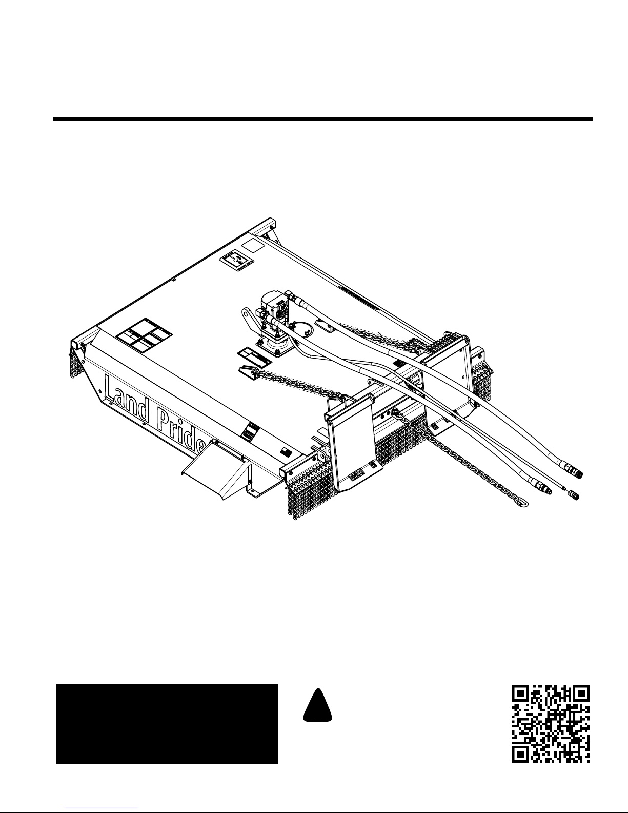
A pivoting and adjustable front mounted gauge wheel
with a single laminated tire is available to make mowing
even easier by pre-setting the mowing height and
allowing the cutter to float overuneven terrain. Hydraulic
hoses and a case-drain line are provided as standard
equipment but compatible couplers for attachment to the
individual skid steers auxiliary hydraulic outlets will need
to be provided by dealers or customers.
The addition of a Land Pride SC2660 or SC2672 Skid
Steer Rotary Cutter to your arsenal of skid steer
attachments will dramatically increase the versatility and
value of your personal skid steer investment.
See “Specifications & Capacities” on page 28 and
“Features & Benefits” on page 30 for additional
information and performance enhancing options.
Using This Manual
•This Operator’s Manual is designed to help familiarize
you with safety, assembly, operation, adjustments,
troubleshooting, and maintenance. Read this manual
and follow the recommendations to help ensure safe
and efficient operation.
•The information contained within this manual was
current at the time of printing. Some parts may change
slightly to assure you of the best performance.
•To order a new Operator’s or Parts Manual contact
your authorized dealer. Manuals can also be
downloaded, free-of-charge from our website at
www.landpride.com.
•Store your Operator’s manual in the dry storage tube
for future reference. See Figure 1 on page 8 for
location of storage tube.
Terminology
“Right” or “Left” as used in this manual is determined by
facing the direction the machine will operate while in use
unless otherwise stated.
Definitions
IMPORTANT: A special point of information related
to the following topic. Land Pride’s intention is that
this information must be read and noted before
continuing.
NOTE: A special point of information that the
operator should be aware of before continuing.
Introduction
Land Pride welcomes you to the growing family of new
product owners.
ThisRotary Cutterhasbeen designedwithcare andbuilt
by skilled workers using quality materials. Proper
assembly,maintenance,andsafeoperatingpracticeswill
help you get years of satisfactory use from the machine.
Application
The SC2660 and SC2672 Series Skid Steer Rotary
Cutters are built and designed by Land Pride for cutting
on gently sloping or slightly contoured right-of-ways,
pastures, set aside acres, and row crop fields. These
skid steer mounted cutters provide unparalleled access
to tightly restricted areas such as under fences, in and
around boxed in corner sections of corrals and out
buildings, vineyard, nursery rows, wooded lots, and
approaches to ditches and waterways. The 60" or 72"
cutting width, 8"offset capability to the right, 2" cutting
capacity, 1.5" to 18" cutting height range, and the
universal skid steer floating-hitch mounting plate make
the SC2660 and SC2672 highly versatile and easy to
use. The SC2660 is compatible with and designed for
attachment to skid steers having 1500 psi to 3500 psi
operating pressure and flow rates in the 11-15 gpm,
15-21 gpm, or 18-27 gpm ranges. The SC2672 is
compatible with and designed for attachment to skid
steers having 1500 psi to 3500 psi operating pressure
and flow rates in the 15-21 gpm, or 18-27 gpm ranges.
The SC2660 and SC2672 provide very high and clean
cutting blade tip speeds but owner/operators will need to
select the motor that is appropriately matched to their
skid steers hydraulic flow and pressure capabilities. Our
lowvolume motor,whichisavailableontheSC2660only,
produces a blade tip speed of 18,540 fpm at
15 gpm. Medium volume and high volume motors are
available for both models. On the SC2660, our medium
volume motor produces 18,850 fpm at 21 gpm, and our
high volume motor produces 19,000 fpm at 27 gpm. On
the SC2672, our medium volume motor produces
17,200 fpm at 21 gpm, and our high volume motor
produces 18,550 fpm at 27 gpm. Each unit is equipped
with two 1/2" x 4"updraft blades and a heavy duty round
pan stump jumper. A deflector chute is located to the left
rearsideofthecuttertoprevent clogging in heavycutting
conditions.
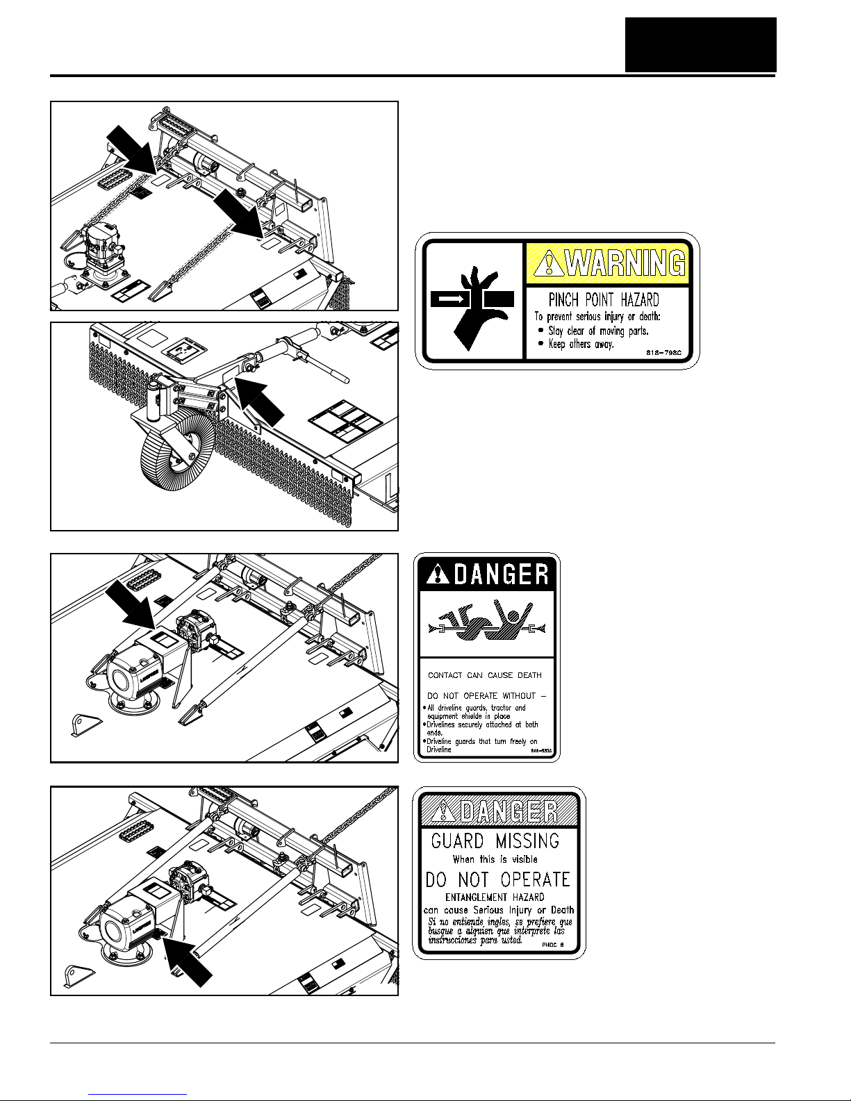
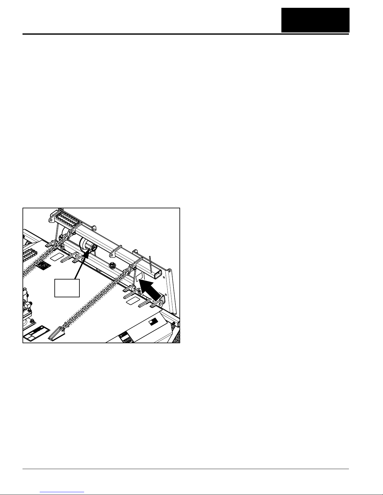
The SC2660 and SC2672 come standard with a front
mounted single row chain guard, a rear mounted double
row chain guard, and a safety chain to restrict deck lift
height. Four corner-mounted skid shoes are provided to
reducewearand tokeepthecutter from bottomingout. A
Lexan protective cab door is available as optional
equipment or owner/operators may choose to use a
protective door provided or made available by their skid
steer supplier/manufacturer.

8
Introduction
SC2660 & SC2672 Skid Steer Rotary Cutter 326-025M 4/24/12
Table of Contents
Owner Assistance
The Warranty Registration card should be filled out by
the dealer at the time of purchase. This information is
necessary to provide you with quality customer service.
If customer service or repair parts are required contact a
LandPride dealer.Adealer has trainedpersonnel,repair
parts and equipment needed to service the Rotary
Cutter.
The parts on your Rotary Cutter have been specially
designedandshouldonlybereplacedwithgenuineLand
Pride parts. Therefore, should your cutter require
replacement parts go to your Land Pride Dealer.
Serial Number
Model No. _____________Serial No. _______________
For quick reference and prompt service, record model
number and serial number in the spaces provided above
and again on warranty page 33. Always provide model
number and serial number when ordering parts and in all
correspondences with your Land Pride dealer. Refer to
Figure 1 for location of your serial number plate.
Serial Number Plate Location
Figure 1
24539
Manual
Storage
Tube
Further Assistance
Your dealer wants you to be satisfied with your new
Rotary Cutter. If for any reason you do not understand
any part of this manual or are not satisfied with the
service received, the following actions are suggested:
1. Discuss the matter with your dealership service
manager making sure he is aware of any problems
you may have and that he has had the opportunity to
assist you.
2. If you are still not satisfied, seek out the owner or
general manager of the dealership, explain the
problem and request assistance.
3. For further assistance write to:
Land Pride Service Department
1525 East North Street
P.O. Box 5060
Salina, Ks. 67402-5060
E-mail address
lpser[email protected]

9
Section 1: Assembly & Set-up
4/24/12 SC2660 & SC2672 Skid Steer Rotary Cutter 326-025M
Table of Contents
Skid Steer Requirements
The Rotary Cutter is designed to attach to Skid Steer
Loaders with the following minimum requirements:
SAE Lift Capacity
SAE Lift Capacity . . . . . . . . . . . . . . . . . . . . .1200 lbs.
Operating Hydraulic Pressure
Hydraulic Pressure Rating . . . . . . . .1500 - 3500 PSI.
Hydraulic Flow Rate
Low Volume Motor & Hoses . . . . . . . . . 11 - 16 GPM.
Medium Volume Motor & Hoses . . . . . . 17 - 21 GPM.
High Volume Motor & Hoses. . . . . . . . . 22 - 27 GPM.
Hydraulic Connections
Hydraulic Hoses. . . . . . . . . . . . .2 - Hydraulic Outlets
Case Drain Hose . . . . . . . . . . . . .1 - Hydraulic Outlet
Protective Equipment
The Skid Steer MUST be equipped with a protective
door shield. A universal Operator Protective Door
shield is available from Land Pride or owner may
chose to use a protective door provided by their skid
steer supplier. Refer to Page 13 and 22 for additional
information and Land Pride installation instructions.
Skid Steer Weight . . . . . . . . . . . . .See warning below
!WARNING
Ballast may need to be added to your Skid Steer to maintain
steering control and to prevent tipping of the Skid Steer. Refer
to your tractor’s Operator’s Manual to determine proper
ballast requirements.
Dealer Preparations
Pre-Assembly Checklist
All hardware from the factory has been installed. If a
part or fastener is temporarily removed for assembly,
remember where it goes. Keep parts separated.
Be sure the parts get used in the correct location. By
double checking while you assemble, you will lessen
the chance of using a bolt incorrectly that may be
needed later. Use Parts Manual to identify location of
parts you are unsure of where they are used.
All grease fittings are in place and lubricated.
Miscellaneous assembly tools: hammer, tape measure,
assortment of wrenches and spirit level.
Have fork lift or loader along with chains and safety
stands sized for the job ready for the assembly task.
Auxiliary weights (depending on Skid Steer size).
Have a minimum of 2 people at hand while assembling.
Safety decals are legible and undamaged.
Loose parts bag/box shipped with the Rotary Cutter.
IMPORTANT: Skid Steer must be equipped with a
case drain system.
Read and understand the operator’s manual for your
cutter. An understanding of how it works will aid in the
assembly and setup of your cutter.
This Rotary Cutter has been partially assembled at the
factory. However, some assembly will be necessary.
It is best to go through the Pre-Assembly Checklist
before assembling the cutter. Speed up your assembly
task and make the job safer by having all the needed
parts and equipment readily at hand.
Ensure that the intended Skid Steer conforms to the
requirements stated under the heading “Skid Steer
Requirements” on page 9.
Uncrating
!WARNING
Always secure cutter with an overhead crane, fork lift, or
other suitable lifting device before removing hardware and
bands that secure the Rotary Cutter to its shipping crate. The
cutter can suddenly fall causing serious injury or death.
1. Secure deck with an overhead crane, fork lift, or
othersuitablemeansbefore cutting shippingsupport
bands and unbolting cutter from shipping crate.
2. Cut bands securing parts bags to the shipping crate.
3. Remove bolts securing hitch to the shipping crate.
4. Cut center band securing hitch to shipping crate.
5. Carefully lower cutter onto its skids or onto support
stands capable of supporting the cutter.
6. Remove wood from under the front chain guard.
Float Chain Assembly
Refer to Figure 1-1:
1. (Not Shown) Unbolt and remove shipping brace bars
extending from hitch plate to center of deck.
2. Attach clevis end (#1) of float chains (#4) to hitch
plate with 9/16" clevis pins (#2) and cotter pins (#3).
Bend cotter pin legs to keep them from falling out.
3. Install other end of float chains (#4) to deck with
1/2" clevis pins (#5) and 1/8" cotter pins (#6). Bend
cotter pin legs to keep them from falling out.
Figure 1-1
25835
Section 1: Assembly & Set-up

10
Section 1: Assembly & Set-up
SC2660 & SC2672 Skid Steer Rotary Cutter 326-025M 4/24/12
Table of Contents
SC2660 Motor And Hose Assembly
Your Skid Steer Rotary Cutter is factory supplied with
one of three motors mounted to the deck. Make sure you
checkGPMratingonthe hydraulicmotordecalto verify if
it matches your Skid Steer’s GPM rating. Skip assembly
instructions below if the motor GPM rating matches your
Skid Steer.
See “Motor and Hose Assembly” on page 21 to
properly select a motor that matches your Skid Steer.
Refer to Figure 1-2:
1. Remove fasteners (#1, 2, 3 & 4). Keep fasteners for
reassembly of new motor.
2. Remove existing motor and hose assembly (#5).
Clean old gasket (#6) from gearbox flange (#7).
3. Place new gasket (#6) onto gearbox flange (#7).
4. Gently lower new motor and hose assembly (#5)
onto gasket (#6) with hoses extending towards the
hitch plate.
5. Secure hydraulic motor assembly with the four
existing 1/2"-13 x 2 1/4" lg. GR 5 hex head bolts (#1),
flatwashers (#4), lockwashers(#3), and 1/2"-13 hex
huts (#2). Tighten nuts to the correct torque. See
“Torque Values Chart for Common Bolt Sizes” on
page 32.
SC2660 Motor and hose Assembly
Figure 1-2
SC2672 Motor And Hose Assembly
Your Skid Steer Rotary Cutter is factory supplied with
one of three motors mounted to the deck. Make sure you
checkGPMratingonthe hydraulicmotordecalto verify if
it matches your Skid Steer’s GPM rating. Skip assembly
instructions below if the motor GPM rating matches your
Skid Steer.
See “Motor and Hose Assembly” on page 21 to
properly select a motor that matches your Skid Steer.
24545
Decal Location Stating
Motor GPM Rating
Refer to Figure 1-3:
1. Remove fasteners (#9 & #10) and coupling
guard (#8). Keep fasteners and coupling guard for
reassembly of new motor.
2. Remove fasteners (#1, 2, 3 & 4). Keep fasteners for
reassembly of new motor.
3. Remove existing motor and hose assembly (#5).
Clean old gasket (#6) from mounting flange (#7).
4. Place new gasket (#6) onto mounting flange (#7).
5. Gently slide new motor and hose assembly (#5) onto
coupling (#12) with hoses extending towards the
hitch plate.
6. Secure hydraulic motor assembly with the four
existing 1/2"-13 x 2 1/4" lg. GR 5 hex head bolts (#1),
flatwashers (#4), lockwashers(#3), and 1/2"-13 hex
huts (#2). Tighten nuts to the correct torque. See
“Torque Values Chart for Common Bolt Sizes” on
page 32.
7. Reattach coupling guard (#8) with 5/16" spring lock
washers (#10) and 5/16"-18 x 3/4" GR5 hex head
cap screws (#9). Tighten nuts to correct torque.
SC2672 Motor and hose Assembly
Figure 1-3
SC2672 Vented Dipstick
Figure 1-4
25732
Decal Location Stating
Motor GPM Rating
IMPORTANT: Rotary Cutters are shipped with a
solid plug in the gearbox to prevent loss of oil during
shipping and handling. The solid plug on top of the
gearbox must be replaced with a vented dipstick. Do
not operate cutter without vented dipstick installed.
20822
Oil Level
Plug
Remove
Solid Plug Install
Vented Dipstick
DO NOT
OVERFILL!

11
Section 1: Assembly & Set-up
4/24/12 SC2660 & SC2672 Skid Steer Rotary Cutter 326-025M
Table of Contents
Skid Steer Hook--Up
Figure 1-5
24538
Top Angle Bar
Bottom Slots
Height Adjustment Safety Chain
(Attach to Skid Steer’s lower hitch loop.)
Rear Skid Shoe
Female Coupler
Male Coupler
Case Drain Line
Clockwise
Blade Rotation
Blade Bolt Access Hole If connecting hoses to a Kubota CTL, be sure to
route hydraulic hoses through hose loop
mounted on top of the hitch plate on the left side
and Kubota’s Hose Stay KIt.
Zip tie hydraulic hoses
together 24", 43" & 63"
from male and female
coupler ends.
Optional 3/8"
Female Flat
Face Coupler
!DANGER
Hydraulic fluid under pressure can penetrate skin. Wear
protective gloves and safety glasses or goggles when working
with hydraulic systems. Use a piece of cardboard or wood
rather than hands when searching for hydraulic leaks. If
hydraulic fluid is injected into the skin, it must be treated by a
doctor within a few hours or gangrene may result.
8. If attaching to a Kubota CTL, be sure to route
hydraulichosesthroughhoseloopmountedontopof
the hitch plate on its left side.
9. Thread hoses through any hose holders that may be
provided on the machine operating the cutter. If
attachingtoKubotaCTL,threadhosesthroughHose
Stay Kit #S6689. Kubota Hose Stay Kit can be
purchased through your nearest Kubota Dealer. See
your Skid Steer/Tractor Operator’s Manual for
instruction on how to use these hose holders.
10. Remove plastic cap from case drain hose and attach
optional coupling to the hose or customer may
supply their own coupler. (See “Optional Case
Drain Coupling” on page 22)
11. Connect case drain hose to reservoir outlet.
12. Connect male and female couplers on the hydraulic
motor hoses to the Skid Steer high pressure outlets.
13. Operate skid steer to check blade rotation. Cutter
blades should rotate clockwise when looking at the
blades from above. If cutter blades are rotating
counterclockwise, switch male and female couplers
and reconnect to skid steer outlets.
14. Zip tie hydraulic hoses together at a distance of
24", 43", and 63" from male and female coupler
ends.
Hitch Hook-Up
Refer to Figure 1-5:
!DANGER
A Crushing Hazard exists when hooking-up equipment to a
Skid Steer. Do not allow anyone to stand between Skid Steer
and implement while hooking-up to implement. Do not
operate hydraulic controls while someone is near the Skid
Steer or implement.
1. Make sure hydraulic hoses and height adjustment
safety chain do not interfere with hitch hook-up.
2. Drive Skid Steer slowly to the Rotary Cutter making
sure the front hitch plate of the Skid Steer is parallel
with the Rotary Cutter hitch.
3. Tilt top of Skid Steer hitch plate slightly forward.
4. Place top of Skid Steer hitch plate under the Rotary
Cutter top angle bar.
5. Slowly lift Skid Steer’s hitch until Rotary Cutter’s
hitch and Skid Steer’s top angle bar have come
together.
6. Push lock handles of the Skid Steer down so that the
pins go through the bottom slots of the Rotary
Cutter’s hitch and the handles lock down.
7. Loop height adjustment safety chain forward down
andunder2"x3"tubeandthenattachtoSkid Steer’s
lower hitch loop. See “Height Adjustment Safety
Chain” on page 15.
Hydraulic Hose Hook-up
Refer to Figure 1-5:
Two high pressure hydraulic outlets are required for the
hydraulic motor and one outlet for the case drain.

12
Section 1: Assembly & Set-up
SC2660 & SC2672 Skid Steer Rotary Cutter 326-025M 4/24/12
Table of Contents
Gauge Wheel Assembly (Optional)
Required Tools:
•1 ea. - Small hammer
•2 ea. - 1/2" drift punches or alignment tools
•2 ea. - 9/16" box end wrench
•2 ea. - 3/4" box end wrench
•1 ea. - Torque wrench with 9/16" and 3/4" sockets
Assembly Instructions:
Refer to Figure 1-6:
.
1. Remove four3/8"-16x3" lg. GR5hexheadbolts (#2)
in the center of the front chain guard. Keep bolts,
washers, and whiz nuts for reassembly of gauge
wheel arm (#1).
2. Install gauge wheel deck mount (#1) by inserting
1/2" x 3 3/4" lg. GR8 bolt (#3) through 1/2" flat
washer (#8), gauge wheel mounting bracket (#1),
anddecktube.Secure bolt with 1/2" flat washer (#8),
lockwasher(#7),andhexnut(#4). Do not torque nut
at this time. Finger tighten nut only.
Gauge Wheel Assembly
Figure 1-6
IMPORTANT: Do not enlarging any of the 5 bolt
holes used for mounting the gauge wheel. Enlarging
bolt holes can severely decrease the longevity of
your gauge wheel operation.
24547
3. Check alignment of gauge wheel front mount holes
with chain guard holes. Skip to step 4 if mounting
holes are in alignment. If gauge wheel mounting
holes are not in alignment, loosen remaining chain
guard bolts and realign chain guard as follows.
a. Realign chain guard by inserting drift punches in
the outer two gauge wheel mounting holes. Tap
punches in with a hammer until secure. Do not
remove punches at this time.
b. Insert 3/8"-16 x 3" lg. GR5 bolts (#2) with 3/8" flat
washers (#6) through the two inside holes.
Secure bolts with 3/8" whiz nuts (#5). Tighten
bolts to 31 ft-lbs.
c. Remove left hand drift punch and install
3/8" x 3" lg. GR5 hex bolt (#2), flat washer (#6),
and whiz nut (#5). Tighten 3/8" bolt to 31 ft-lbs.
d. Remove right hand drift punch and install
3/8" x 3" lg. GR5 hex bolt (#2), flat washer (#6),
and whiz nut (#5). Tighten 3/8" bolt to 31 ft-lbs.
e. Tighten remaining chain guard bolts to 31 ft-lbs.
f. Skip to step 5.
4. If gauge wheel mounting holes are in alignment,
Install four 3/8" x 3" lg. GR5 hex bolts (#2), flat
washers (#6), and whiz nuts (#5). Tighten 3/8" bolts
to 31 ft-lbs.
5. Tighten 1/2" gauge wheel top bolt (#3) to 76 ft-lbs.
6. Attach heavy duty ratchet jack (#14) to cutter frame
andtogauge wheel deckmount (#1)with1" x 33/16"
lgclevispins(#11).Secure withhairpin cotters (#10).
7. Insert four 1 1/2" I.D. machine washers (#9) over
gauge wheel spindle (#13).
8. Insert gauge wheel spindle (#13) through yoke in
gauge wheel deck mount (#1) and 1 1/2" I.D.
machine washer (#9). Secure gauge wheel with
3/8" x 2 1/2" lg. roll pin (#12).

13
Section 1: Assembly & Set-up
4/24/12 SC2660 & SC2672 Skid Steer Rotary Cutter 326-025M
Table of Contents
Skid Shoe Replacement
Figure 1-7
Operator Protective Door
Figure 1-8
24546
Skid Steer
Hand Hold
If needed, Locate & Cut
Notches in Door For
U-bolts Clearance.
If Needed, Locate
& Cut Notch in
Door To Clear Skid
Steer Frame.
Hook Elastic Tie-Down
To Skid Steer Cage To
Keep Door Closed.
24608
Skid Shoe Assembly (Optional)
Refer to Figure 1-7:
Cutters ordered with skid shoes are shipped loose.
Install skid shoes as follows:
1. Raise the Rotary Cutter 3" or more off the ground
andplacesupportblocksunderthecutter.Makesure
support blocks are positioned so they will not
interfere with skid shoe installation.
2. Lowercutterontosupport blocks, place Skid Steerin
park, set park brakes, shut Skid Steer off, and
remove switch key.
3. Install short skid shoe (#2) to the back left deck
corner as shown with 3/8"-16 x 1 1/4" GR5 plow bolts
(#2), flat washers (#6), lock washers (#5), and 3/8"
lock nuts (#4). Torque lock nuts (#4) to 31 ft-lbs.
4. Install long skid shoes (#1) to the remaining three
deck corners with 3/8"-16X1 1/4" GR5 plow bolts (#2),
flat washers (#6), lock washers (#5), and 3/8" lock
nuts (#4). Torque lock nuts (#4) to 31 ft. lbs.
5. Raise cutter up and remove support blocks.
Operator Protective Door (Optional)
Refer to Figure 1-8:
!WARNING
Do not drill holes in the ROPS (Roll Over Protection System)
to attach this Operator Protective Door. Drilling unapproved
holes in the ROPS can weaken the structure and void its
warranty.
Instructions below are for installing land Pride’s optional
Operator Protective Door. See your Skid Steer/Tractor
Operator’s Manual for installation instructions of their
Operator Protective Door.
1. Cut notches in protective door as needed to provide
clearance around u-bolts and Skid Steer frame.
2. Install Operator Protective Door to the Skid Steer’s
hand hold with two u-bolts (#3), flat bars (#2), and
four nuts (#1) as shown. Tighten nuts to correct
torque.

14
Section 2: Adjustments
SC2660 & SC2672 Skid Steer Rotary Cutter 326-025M 4/24/12
Table of Contents
Hitch Positioning
Refer to Figure 2-1:
TheRotaryCutterhitchisdesigned tobecenteredonthe
cutter or offset to position the cutter to the right.
Offsetting the cutter to the right will allow the unit to cut
close to obstacles.
Hitch Mounted Offset
1. Drive roll pins (#7) through one of two holes in both
pivot pins (#8).
2. Align hitch pivot pin bushings (#3) with cutter
mounting lug holes (A1).
3. Insert hitch pins (#8) through mounting lug
holes (A1) and hitch bushings (#3).
4. Insert cotter pins (#7) through holes in pivot pins
(#8). Bend one or both legs of each cotter pin to
secure them in place.
5. Attach Floating Chains (#4) to hitch plate lugs at
positions marked (B1) with chain pins (#5).
6. Insert cotter pins (#2) through chain pin holes and
bend one or both legs of each cotter pin to secure
them in place.
Hitch Mounted Centered
1. Drive roll pins (#7) through one of two holes in both
pivot pins (#8).
2. Align hitch pivot pin bushings (#3) with cutter
mounting lug holes (A2).
3. Insert hitch pivot pins (#8) through mounting lug
holes (A2) and hitch bushings (#3).
4. Insert cotter pins (#7) through holes in pivot pins
(#8). Bend one or both legs of each cotter pin to
secure them in place.
5. Attach Floating Chains (#4) to hitch plate lugs at
positions marked (B2) with chain pins (#5).
6. Insert cotter pins (#2) through chain pin holes and
bend one or both legs of each cotter pin to secure
them in place.
Section 2: Adjustments
Hitch Offset
Figure 2-1
24548

15
Section 2: Adjustments
4/24/12 SC2660 & SC2672 Skid Steer Rotary Cutter 326-025M
Table of Contents
Height Adjustment Safety Chain
!WARNING
Always secure cutter deck in the up position with solid
supports or by locking the hydraulics before working around
or under a raised deck. Never work under equipment
supported by hydraulics. Hydraulics can drop equipment if
controls are actuated or if hydraulic lines burst. Either
situation can drop the cutter instantly even when power to the
hydraulics is shut off.
!DANGER
Do not raise cutter higher than 16 1/2" off the ground. Raising
cutter higher can cause serious bodily injury and/or death.
Use safety limit chain to limit cutter height.
!DANGER
Do not tilt hitch plate to raise front of cutter higher than the
rear. Raising front of cutter can cause serious bodily injury
and/or death.
Nominal Cutting Height
Figure 2-2
16 1/2"
Maximum Lift
Gauge Wheel
Ratchet Jack
Skid Steer
Lower Hitch Loop
Ground Level
Bottom of Rear
Skid Shoes
24586
Quick Link Coupler
Cutter Hitch Plate
Height Adjustment
Safety Chain
Refer to Figure 2-2:
Forsafety,thecutterrearskidshoesshouldnotberaised
higher than 16 1/2" off the ground (18" Maximum cutting
height).
1. Raise cutter’s rear skid shoes slightly less than
16 1/2" off the ground.
2. Run height adjustment safety chain from under the
2" x 3" hitch tube to the Skid Steer lower hitch loop.
Thread chain through the hitch loop and back
towardsthe hitchplate. Connect quicklinkcoupler to
a chain loop as shown.
3. Raise cutter up until the safety chain is tight. Check
height of rear skid shoes.
4. If rear skid shoes are higher than 16 1/2" above
ground level, lower cutter and make necessary
adjustmentstothesafetychain tolimitrearskidshoe
height to 16 1/2" maximum.
5. Tighten quick link coupler nut to secure safety chain.
NOTE: Two people may be required to install and
adjust the safety chain.

16
Section 2: Adjustments
SC2660 & SC2672 Skid Steer Rotary Cutter 326-025M 4/24/12
Table of Contents
Deck Leveling with
Optional Gauge Wheel
Refer to Figure 2-3:
!WARNING
Engage parking brake, disengage power to cutter, shut offSkid
Steer, remove key and ensure that all moving parts have come
to a complete stop before dismounting from Skid Steer.
IMPORTANT: The blades should be positioned to
cut material only at the front of the cutter. If deck is
levelorbackofcutterislowerthanthe front, thenthe
blades are subject to continuous material flow
resulting in cutting clumps at the discharge chute,
horsepower loss, high blade wear, and frequent
blade sharpening.
NOTE: Nominal Cutting Height is the distance
from bottom of cutter blade to ground level at the
front of the cutter. Subtract 1 1/2" from Nominal
Cutting Height to determine distance (A). Distance
(A) is measured from bottom of front skid shoes to
ground level.
1. Park Skid Steer with cutter on a level surface.
2. Adjust ratchet jack to raise gauge wheel up until it is
even with bottom of front skid shoes.
3. Use Skid Steer hydraulics to lower Skid Steer lift
armsandto tiltcutterhitch plate angleuntil bottom of
skidshoeatthefrontdeckcornerisdimension(A)off
the ground and the rear deck corner is slightly higher
off the ground than the front deck corner.
4. Adjust ratchet jack to lower gauge wheel until it is at
ground level.
5. With gauge wheel at ground level, use Skid Steer
hydraulics to adjust cutter hitch plate angle until the
float chain sags.
!CAUTION
Do Not over angle hitch plate forward. Over angling can
cause damage to deck, hitch and gauge wheel.
The Rotary Cutter should be operated with gauge wheel
on the ground, slack in float chain, and deck rear slightly
higher off the ground than deck front. As the operator
travels over uneven terrain, the Skid Steer hitch plate tilt
angle and lift arm height may need some readjusting to
maintain correct deck positioning.
Nominal Cutting Height
Figure 2-3
“A”
Gauge Wheel Ratchet Jack Cutter Hitch Plate
Ground Level
Nominal Cutting Height is the
distance from bottom of the
front leading cutting blade to
ground level.
The rear deck corner should be raised
slightly higher above ground level
than the front deck corner.
24585
“A” is 1 1/2" less than Nominal Cutting Height
and is the distance from bottom of Skid Shoe
at the front deck corner to ground level.
Float Chain should sag when gauge wheel is
resting on level ground. Adjust hitch plate
tilt angle to put a sag in the Float Chain.
Height Adjustment
Safety Chain

17
Section 2: Adjustments
4/24/12 SC2660 & SC2672 Skid Steer Rotary Cutter 326-025M
Table of Contents
Deck Leveling without
Optional Gauge Wheel
Refer to Figure 2-4:
!WARNING
Engage parking brake, disengage power to cutter, shut offSkid
Steer, remove key and ensure that all moving parts have come
to a complete stop before dismounting from Skid Steer.
IMPORTANT: The blades should be positioned to
cut material only at the front of the cutter. If deck is
levelorbackofcutterislowerthanthe front, thenthe
blades are subject to continuous material flow
resulting in cutting clumps at the discharge chute,
horsepower loss, high blade wear, and frequent
blade sharpening.
NOTE: Nominal Cutting Height is the distance
from bottom of cutter blade to ground level at the
front of the cutter. Subtract 1 1/2" from Nominal
Cutting Height to determine distance (A). Distance
(A) is measured from bottom of front skid shoes to
ground level.
1. Park Skid Steer with cutter on a level surface.
2. Use Skid Steer hydraulics to lower Skid Steer lift
armsandto tiltcutterhitch plate angleuntil bottom of
skidshoeatthefrontdeckcornerisdimension(A)off
the ground and the rear deck corner is slightly higher
than the front deck corner.
The Rotary Cutter should be operated with float chain
tight to hold front of cutter at the correct cutting height
and lift arms set to hold rear of cutter slightly higher off
the ground than the front.
As the Skid Steer travels over uneven terrain, the Skid
Steer hitch plate tilt angle and lift arm height will need
readjusting frequently to maintain correct deck
positioning.
Nominal Cutting Height
Figure 2-4
A"
Cutter Hitch Plate
Ground Level
24591
Float Chain is kept tight
Nominal Cutting Height is the
distance from bottom of the
front leading cutting blade to
ground level.
“A” is 1 1/2" less than Nominal Cutting Height
and is the distance from bottom of Skid Shoe
at the front deck corner to ground level.
The rear deck corner should be raised
slightly higher above ground level
than the front deck corner.
Height Adjustment
Safety Chain

18
Section 3: Operating Procedures
SC2660 & SC2672 Skid Steer Rotary Cutter 326-025M 4/24/12
Table of Contents
Section 3: Operating Procedures
Operating Checklist
Hazard control and accident prevention are dependent
upon the awareness, concern, prudence, and proper
training involved in the operation, transport, storage,
maintenance of the Rotary Cutter. Therefore, it is
absolutely essential that no one operates the Rotary
Cutter without first having read, fully understood, and
becometotallyfamiliarwiththeOperator’sManual.Make
sure the operator has paid particular attention to:
•Important Safety Information, page 1
•Section 1: Assembly & Set-up, page 9
•Section 2: Adjustments, page 14
•Section 3: Operating Procedures, page 18
•Section 5: Maintenance & Lubrication, page 23
The following inspections should be performed before
operating your Skid Steer cutter.
Safety Information
!DANGER
Hydraulic fluid under pressure can penetrate skin. Wear
protective gloves and safety glasses or goggles when working
with hydraulic systems. Use a piece of cardboard or wood
rather than hands when searching for hydraulic leaks. If
hydraulic fluid is injected into the skin, it must be treated by a
doctor within a few hours or gangrene may result.
!DANGER
Keep others away while cutter is operating. It can discharge
objects at high speeds. Therefor, the use of front and rear
safety guards is strongly recommended when cutting along
highways and in areas where people may be present. Stop
blade rotation if a bystander is within several hundred feet!
!DANGER
Do not use cutter as a fan. Cutting blades are not properly
designed or guarded for this use. Using cutter as a fan can
result in injury or death.
!DANGER
Do not cut on steep inclines. The tractor could flip over
causing damage to the equipment, serious injury or death.
Operating Checklist
✔Check Reference
Make Sure all guards and shields are in place
and secure. Page 1
Inspect Hydraulic hoses for wear, damage,
and hydraulic leaks. Replace damaged and
worn hoses with genuine Land Pride parts.
Page 3
Grease all fittings. Refer to “Lubrication”Page 26
Check the Rotary Cutter initially and periodically
for loose bolts & pins, Torque Values Chart.Page 32
!DANGER
Do not operator the cutter with cutting blades raised higher
than 18" off the ground. Always use the height adjusting safety
chain to limit cutting height to 18" (16 1/2" skid shoe height).
Raising the cutter higher can throw debris at the operator and
cause serious injury or death.
!DANGER
Shields must be secured in place when operating to avoid
injury or death.
!WARNING
Do not become entangled in the hydraulic hoses. Tripping
over the hoses while entering or exiting the Skid Steer
operator station can cause serious injury to the body.
!WARNING
Do not operate Rotary Cutter without an Operator Protective
Door mounted to the cab and protective eye wear such as
safety glasses or goggles. Flying objects from the cutter can
cause serious injury to the body and eyes.
!WARNING
Do not travel too fast. The rougher the terrain, the slower you
must travel. Always travel at a speed slow enough to be able
to adjust the deck height before running it into the ground.
Remember, sudden dropping of the front tires can slam the
deck into the ground. Also, travel slow enough to stop before
running or turning into obstacles ahead and on either side.
!WARNING
Do not use cutter to lift or carry objects; to pull fence posts,
stumps or other objects; or to tow other equipment. Doing so
can damage the cutter, cause serious bodily injury or death.
!WARNING
Never allow riders including children on the cutter. A person
can fall and be ran over causing serious injury or death.
!WARNING
Do not use deck as a working platform. The deck is not
properly designed or guarded for this use. Using deck as a
working platform could cause serious injury or death.
!CAUTION
Do not exceed rated cutting capacity of your cutter! See
Specifications & Capacities for specified cutting capacity.
Using this cutter for any other work can damage drive
components, cutter blades, and deck components!
This manual suits for next models
1
Table of contents
Other Land Pride Brush Cutter manuals

Land Pride
Land Pride RC5015 User manual

Land Pride
Land Pride RC5010 User manual

Land Pride
Land Pride RC45180 User manual

Land Pride
Land Pride RC5014 User manual

Land Pride
Land Pride RC5515 User manual

Land Pride
Land Pride RCP2660 User manual

Land Pride
Land Pride RCR26 series User manual

Land Pride
Land Pride RCR3515 User manual

Land Pride
Land Pride RCS3596 User manual

Land Pride
Land Pride RCR2510 Series User manual