Assembly Instructions
Third Function Valve Kit #380-149A Installation Instructions Manual No. 380-151M 5/3/19
2
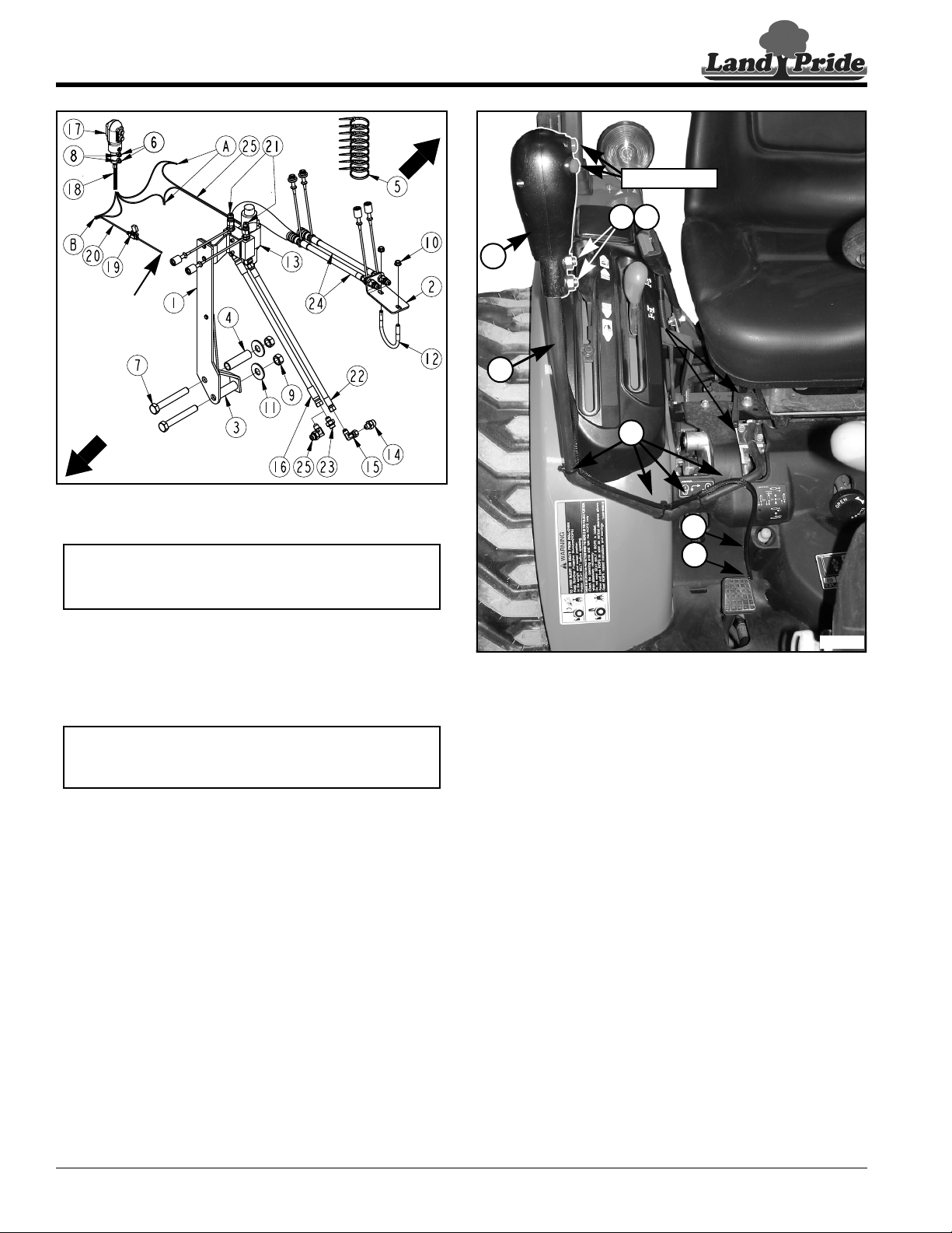
Figure 3
Refer to Figure 3:
7. Screw the larger hydraulic adapter (#14) to power
beyond port at the loader valve until tight.
8. Screw elbow (#15) to adapter (#14) until tight.
9. Locate 48" long hose (#22) attached to “P” port in
valve (#13). Screw hose to elbow (#15) until tight.
10. Locate port on right-hand side of tractor where steel
tube in step 6 was removed. Screw the smaller
hydraulic adapter (#23) or 90oadapter (#25) to this
port until tight.
11. Locate 62" long hose (#16) attached to “T” port in
valve (#13). Screw hose to adapter (#23) or 90o
adapter (#25)until tight.
12. Secure hoses (#16 & #22) to underside of tractor with
cable ties (#5).
13. Install right rear wheel and snug-up wheel lug nuts.
14. Jack axle up and remove jack stand.
15. Lower tractor down and tighten rear wheel lug nuts in
a crisscross pattern. Refer to tractor Operator's
Manual for proper torque value.
16. Remove chocks.
17. Check tractor hydraulic fluid level. If low, add
recommended hydraulic fluid. Refer to your tractor
Operator's Manual for recommended hydraulic fluid
and procedure for checking hydraulic fluid level.
37027
Right-
Hand Side
Left-Hand
Side
Attach to
positive (+)
post on the
tractor battery
NOTE: Depending on tractor model and/or options,
the seat support frame may need to be removed to
performing the following steps.
NOTE: Depending on tractor model and/or options,
either straight adapter (#23) or 90oadapter (#25)
will be used.
Figure 4
Control Lever Assembly
Refer to Figure 3 & Figure 4:
1. Remove existing knob (not shown) from end of
control lever “D”.
2. Install new joystick (#17) over end of control lever “D”
with push buttons facing operator as shown.
3. Tighten set screws (#6) against control lever. Tighten
jam nuts (#8) to secure set screws (#6).
4. Thread joystick wiring harness (#18) through
hole “E” beneath rubber floor mat.
Refer to Figure 3:
5. Reference Connections “A”: Connect one
black wire in harness (#18) to one black wire in
harness (#25) and the other black wire in
harness (#18) to one white wire in harness (#25).
6. Reference Connection “B”: Connect the two red
wires from joystick (#17) to wire (#20) on one end of
fuse holder (#19).
7. Connect wire (#20) on opposite end of fuse
holder (#19) to the positive (+) post on the tractor
battery.
Refer to Figure 4:
8. Secure wiring with cable ties (#5) as needed.
37028
17
6 8
D
5
E
18
Push Buttons