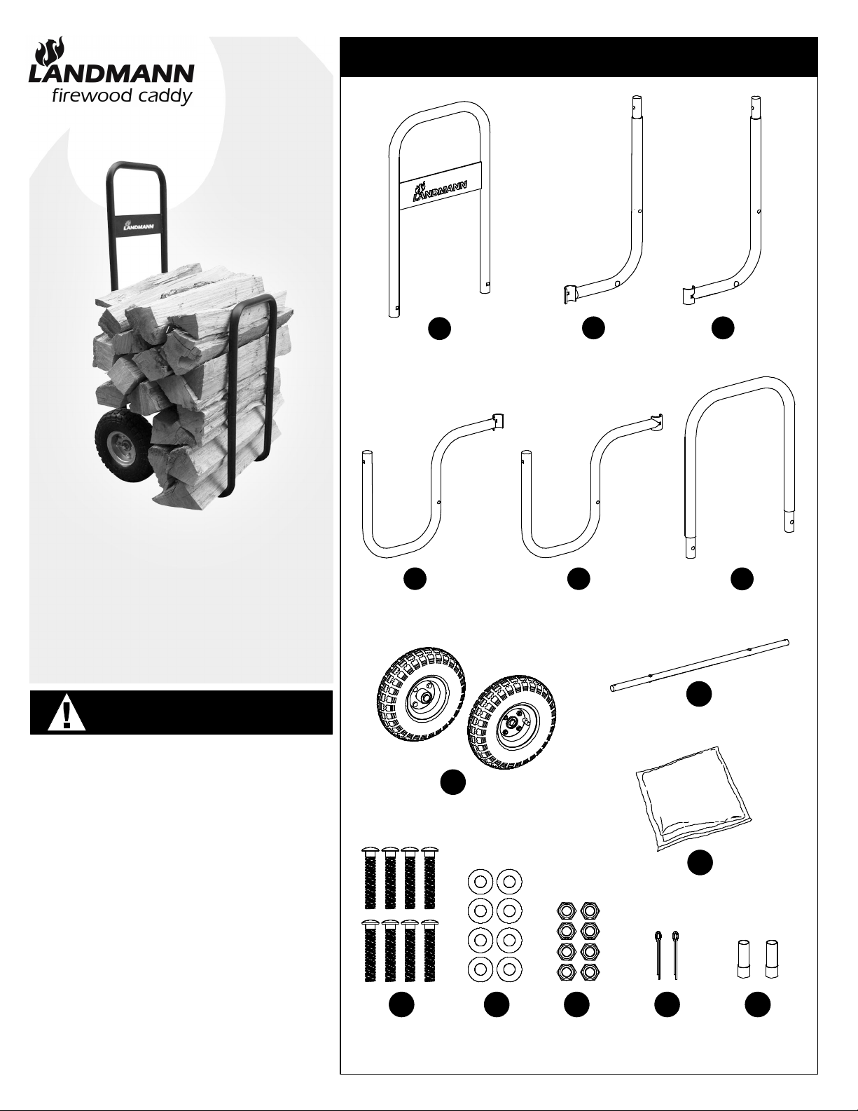
Landmann 82427 Quick setup guide

Thank you for your purchase of the Firewood Caddy with
Cover. At Landmann USA, we strive to provide you with
an easy to use, easy to assemble product. Should you
have questions, issues, a defective part or if you have any
questions concerning its use, please contact us at:
customerservice@landmann-usa.com
-OR-
1-800-321-3473 M-F 8-5 Eastern Time
Proof of purchase may be required.
Landmann® Limited
Distributed by Landmann® USA
Cartersville, GA 30120
www.landmann-usa.com
Made in China
© 2012 Landmann USA
FIREWOOD CADDY
READ FIRST!
RULES FOR SAFE USE
• DO NOT USE OR STORE NEAR SOURCES OF HEAT.
• DO NOT OVERLOAD.
• THE MAXIMUM WEIGHT CAPACITY IS 150 LBS.
• LOAD WOOD CAREFULLY AND DISTRIBUTE FIREWOOD
EVENLY ON THE FIREWOOD CADDY.
• USE CAUTION AS FIREWOOD MAY SHIFT DURING USE.
• DO NOT OVER INFLATE THE TIRES!
• SLOWLY AND CAREFULLY INFLATE THE TIRES TO 30 PSI.
• MAXIMUM TIRE PRESSURE IS 30 PSI, DO NOT EXCEED!
VER.3, 10/5/2012
Assembly and Use
Instructions for Model:
82427
82428
PARTS LIST
(1) HANDLE RAIL (1) AXLE RAIL (1) AXLE RAIL
(1) BOTTOM RAIL (1) FRONT RAIL(1) BOTTOM RAIL
(2) PNEUMATIC TIRE
AND WHEEL
(8) M6 x 35MM
LOCKING BOLT (8) FLAT
WASHER (8) LOCKING
HEXNUT (2) COTTER
PIN (2) AXLE
SPACER
(1) AXLE
(1) COVER
CC2 CC1
BB1BB2
AA
MN J I
K
F
E
P
DD

FIREWOOD CADDY
ASSEMBLY INSTRUCTIONS
For easiest assembly, follow the
assembly steps in this order.
An adjustable wrench or socket wrench
with 10MM socket is needed for assembly.
Assembly time: 10 minutes
1
STEP Assemble axle rail [ CC1 ] to bottom rail [ BB1 ]
using (2) 35MM bolts [ M ], (2) washers [ N ] and (2)
hexnuts [ P ] as shown in DIAGRAM 1.
Repeat step for axle rail [ CC2 ] and bottom rail
[ BB2 ].
2
STEP Insert axle [ E ] through holes in bottom rails. Slide
axle until it comes to the stops. See DIAGRAM 2
and 2B. Slide on the (2) spacers [ I ] as shown.
3
STEP Slide tire and wheel [ F ] onto the axle [ E ] and
spacers [ I ]. Lock tire and wheel to axle using (1)
cotter pin [ J ] per side. Bend cotter pin ends to
lock. See DIAGRAM 2 and 2B.
4
STEP Insert front rail [ DD ] into the bottom rails and
attach using (2) 35MM bolts [ M ], (2) washers [ N ]
and (2) hexnuts [ P ]. See DIAGRAM 3.
5
STEP Insert handle rail [ AA ] into the axle rails and
attach using (2) 35MM bolts [ M ], (2) washers [ N ]
and (2) hexnuts [ P ]. See DIAGRAM 3.
6
STEP Make sure all bolts are tightened securely.
7
STEP Note the tires are only partially inflated for
shipping purposes. Carefully inflate tires to 30 psi
before use.
DO NOT OVER INFLATE THE TIRES!
SLOWLY AND CAREFULLY INFLATE THE
TIRES TO 30 PSI. MAXIMUM TIRE
PRESSURE IS 30 PSI, DO NOT EXCEED!
WARNING!
30 PSI
MAXIMUM TIRE PRESSURE!
DO NOT RETURN PRODUCT TO THE
STORE. IF YOU HAVE QUESTIONS OR
HAVE TROUBLE WITH ASSEMBLY,
PLEASE CALL 1-800-321-3473 FOR
ASSISTANCE.
!
1
DIAGRAM
CC2
BB2
CC1
BB1
NOTE: HOLD LOCKING
BOLT IN THE SQUARE
HOLE WHILE TIGHTENING
THE LOCKING HEXNUT.
M
N
P
3
DIAGRAM
AA
DD
M
NP
M
N
P
2A
DIAGRAM
F
F
I
E
I
2
DIAGRAM
PAGE 2
2B
DIAGRAM
J
8
STEP Use cover to keep firewood out of the weather.

LEÑA CARRITO
•NO USE O ALMACENE CERCA DE FUENTES DE CALOR.
•NO SOBRECARGA.
•LA CAPACIDAD MÁXIMA ES DE 68 KG.
• CARGA DE MADERA CON CUIDADO Y DISTRIBUIR LA
LEÑA UNIFORMEMENTE EN EL LEÑA CARRITO.
•TENGA CUIDADO COMO LEÑA PUEDEN MOVERSE DURANTE USO.
•NO MÁS DE INFLADO DE LOS NEUMÁTICOS!
•DESPACIO Y CON CUIDADO INFLE LOS NEUMÁTICOS A 30 PSI.
•PRESIÓN DE INFLADO MÁXIMA ES DE 30 PSI, NO EXCEDA!
VER.3, 10/5/2012
LISTA DE PIEZAS
(1) MANIJA RIEL (1) EJE RIEL (1) EJE RIEL
(1) RIEL INFERIOR (1) RIEL
DELANTERO
(1) RIEL INFERIOR
(2) RUEDA NEUMÁTICAS
Y RUEDA
(8) PERNO
DE SEGURO
M6 X 35MM
(8) ARANDELA
PLANA (8) SEGURO
TUERCA
HEXAGONAL
(2) CHAVETA (2) ESPACIADOR
EJE
(1) EJE
(1) CUBIERTA
CC2 CC1
BB1BB2
AA
MN J I
K
F
E
P
DD
Gracias por su compra del Leña Carrito. En Landmann USA, nos
esforzamos por brindarle un producto fácil de utilizar y fácil de
ensamblar. Si tiene preguntas, problemas, una pieza
defectuosa o si tiene alguna pregunta con respecto a su uso,
comuníquese con nosotros:
customerservice@landmann-usa.com
-O-
1-800-321-3473 de lunes a viernes de 8 a.m a 5 p.m, hora del
Este
Es posible que se requiera el comprobante de compra.
Landmann® Limited
Distribuído por Landmann® USA
Cartersville, GA 30120
www.landmann-usa.com
Hecho en China
© 2012 Landmann USA
Instrucciones de armado y
uso para el modelo:
82427
82428
¡LEA PRIMERO!
LAS REGLAS PARA EL USO SEGURO

LEÑA CARRITO
INSTRUCCIONES DE MONTAJE
Para facilitar el armado, siga los pasos de
montaje en el orden indicado.
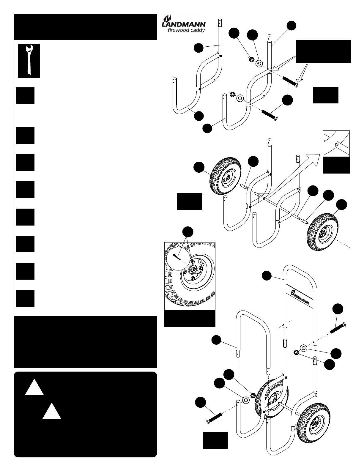
Una llave ajustable llave o con zócalo de
10 mm es necesaria para el montaje.
Tiempo de montaje: 10 minutos
1
PASO Ensamble del eje riel [ CC1 ] para riel inferior
[ BB1 ] usando (2) pernos de 35 mm [ M ], (2)
arandelas [ N ] y (2) tuercas hexagonales [ P ] como
se muestra en el DIAGRAMA 1.
Repita el paso para el riel del eje [ CC2 ] y el riel
inferior [ BB2 ].
2
PASO Inserte el eje [ E ] a través de los agujeros en rieles
inferiores. Deslice el eje hasta que llega a las
paradas. Véase el DIAGRAMA 2 y 2B. Deslice los
espaciadores (2) [ I ] como se muestra.
3
PASO Slide neumático y rueda [ F ] en el eje [ E ] y
espaciadores [ I ]. Bloqueo de neumático y rueda al
eje utilizando (1) el pasador de chaveta [ J ] por
lado. Curva chaveta termina para bloquearlo.
Véase el DIAGRAMA 2 y 2B.
4
PASO Inserte riel delantero [ DD ] sobre los rieles
inferiores y fije usando (2) pernos de 35 mm [ M ],
(2) arandelas [ N ] y (2) tuercas hexagonales [ P ].
Vea el DIAGRAMA 3.
5
PASO Inserto de la manija riel [ AA ] en los rieles del eje y
fije usando (2) pernos de 35 mm [ M ], (2)
arandelas [ N ] y (2) tuercas hexagonales [ P ]. Vea
el DIAGRAMA 3.
6
PASO Asegúrese de que todos los pernos estén bien
apretados.
7
PASO Tenga en cuenta que los neumáticos son sólo
parcialmente inflado para el embarque. Con
cuidado, infle los neumáticos a 30 psi antes de su
uso.
NO MÁS DE INFLADO DE LOS NEUMÁTICOS!
DESPACIO Y CON CUIDADO INFLE LOS
NEUMÁTICOS A 30 PSI. PRESIÓN DE
INFLADO MÁXIMA ES DE 30 PSI, NO EXCEDA!
30 PSI
MÁXIMA PRESIÓN DE
LOS NEUMÁTICOS
!
!
1
DIAGRAMA
CC2
BB2
CC1
BB1
NOTA: MANTENER
PERNO DE BLOQUEO EN
EL ORIFICIO CUADRADO
MIENTRAS APRIETA LA
TUERCA HEXAGONAL
BLOQUEO.
M
N
P
3
DIAGRAMA
AA
DD
M
NP
M
N
P
2A
DIAGRAMA
F
F
I
E
I
2
DIAGRAMA
PÁGINA 2
2B
DIAGRAMA
J
8
PASO Utilice la cubierta para mantener la leña de las
condiciones meteorológicas.
NO DEVUELVA EL PRODUCTO
A LA TIENDA. SI TIENE
PREGUNTAS O PROBLEMAS
DURANTE EL ARMADO, LLAME
AL 1-800-321-3473 PARA
OBTENER AYUDA.
¡ADVERTENCIA!
This manual suits for next models
1
Table of contents
Languages:
Popular Outdoor Cart manuals by other brands

Super Handy
Super Handy GUO098 Operator's manual

Gorilla Carts
Gorilla Carts GOR200B owner's manual

VEVOR
VEVOR JY-UC02C user manual

RAILBLAZA
RAILBLAZA C-TUG quick start guide

Copernicus
Copernicus Teach 'n' Go Cart Assembly guide

Battery Watering Technologies
Battery Watering Technologies Aqua Sub Assembly and operation instructions