Lanex EtherCon TM-170.1 User manual

IOA170-1A
January 2006
LANEX S.A.,8 Ceramiczna Street, 20-150 Lublin, Poland Service: Tel. 048 81 443 96 39
EtherCon
10/100Base-TX/E3 Converter TM-170.1
WITH SNMP AGENT
Operating Manual

10Base-T/100Base-TX/E3 Converter
Operating Manual
IOA170-1A I January 2006
Table of contents
GENERAL PROPERTIES ................................................................................................................ 1
1.1. Description and requirements....................................................................................................1
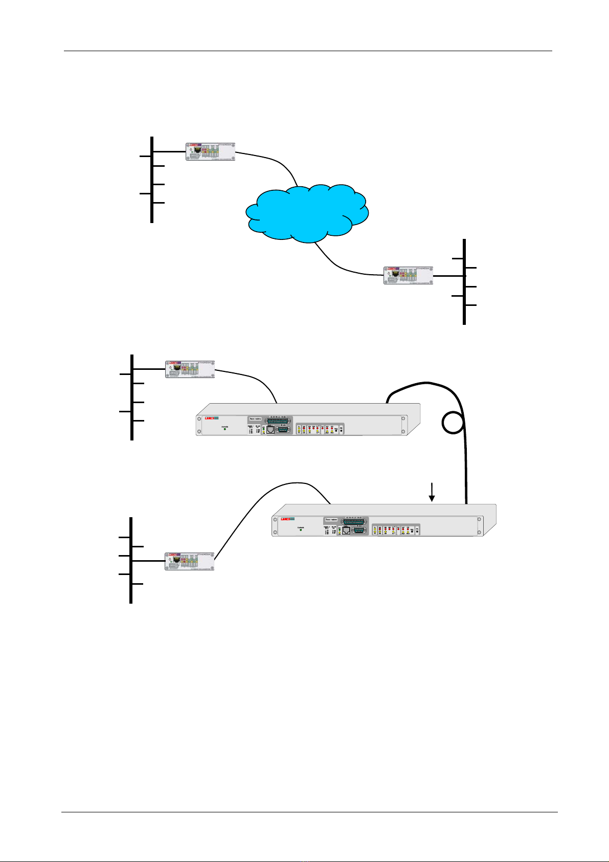
1.2. Examples of application .............................................................................................................2
1.3. Marking .........................................................................................................................................3
2. CONNECTORS AND DIODE INDICATORS...................................................................................... 4
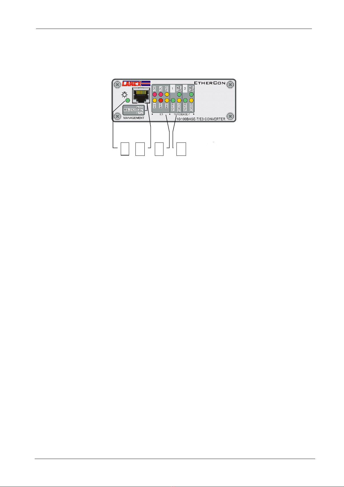
2.1 Front panel........................................................................................................................................4
2.2 Rear panel.........................................................................................................................................5
2.3 Connector properties ......................................................................................................................6
3. FUNCTION DESCRIPTION ........................................................................................................... 7
3.1. Function properties ...........................................................................................................................7
3.2 Clock .................................................................................................................................................7
3.3 Diagnostic and signal indicating systems ....................................................................................7
3.4 Quality management........................................................................................................................8
3.5 Event Log..........................................................................................................................................9
4. INSTALLATION AND OPERATION .............................................................................................. 11
4.1 Introduction ....................................................................................................................................11
4.2 Operating conditions.....................................................................................................................11
4.3 Power source .................................................................................................................................11
4.4 Connecting cables .........................................................................................................................11
4.4.1 E3 Interface .............................................................................................................................11
4.4.2 Ethernet Interface....................................................................................................................11
4.4.3 RS-232 Interface .....................................................................................................................12
4.5 Ethernet interface configuration ..................................................................................................12
4.6 E3 interface configuration.............................................................................................................12
5. SNMP AGENT PROPERTIES ................................................................................................... 13
5.1. Software properties .........................................................................................................................13
5.2. MIB base description.......................................................................................................................14
5.3. Location of the TM-170.1 converter’s MIB base in the registration tree....................................15
5.4. Traps .................................................................................................................................................15
6. CONFIGURING THE CONVERTER USING LANWIN ..................................................................... 16
6.1 Global configuration......................................................................................................................16
6.1.2 New device..............................................................................................................................16
6.1.3 Date and time set up ...............................................................................................................17
6.1.4 Additional information..............................................................................................................17
6.2 Configuring the SNMP agent ........................................................................................................18
6.3 Management system statistics.....................................................................................................18
6.4 Interfaces ........................................................................................................................................20
6.4.1 E3 Interface .............................................................................................................................20
6.4.2 Ethernet Interface....................................................................................................................21
6.4.3 Tab – Global Clock Source .....................................................................................................23
6.5 Event Log........................................................................................................................................24
6.5.1 Tab – Event Log......................................................................................................................24
6.5.2 Tab – Log – Event log filters ...................................................................................................25
6.6 G.826 Statistics ..............................................................................................................................26
6.6.1 Tab - G.826 Statistics - Counters............................................................................................26
7. CONFIGURING THE CONVERTER USING THE VT-100 TERMINAL ............................................... 30
7.1. Launching the configuration and control program......................................................................30
7.2. Description of individual panels ....................................................................................................30
7.2.1. Main menu..................................................................................................................................31
7.3. Configuration ...................................................................................................................................32
7.3.1. System parameters ....................................................................................................................32
7.3.2. Clock configuration.....................................................................................................................33
7.3.3. IP Configuration.......................................................................................................................33
7.3.4. Access configuration from IP ..............................................................................................34
7.3.5. Ethernet interface parameters - Configuration........................................................................35

10Base-T/100Base-TX/E3 Converter
Operating Manual
IOA170-1A II January 2006
7.4. Monitoring ..................................................................................................................................36
7.4.1. Monitoring – E3 ......................................................................................................................36
7.4.2. Monitoring – Ethernet..............................................................................................................37
7.5. Event log.....................................................................................................................................38
7.6. G.826 Statistics..........................................................................................................................39
8. TECHNICAL SPECIFICATIONS .............................................................................................. 42
8.1. Electrical parameters ................................................................................................................42
8.1.1. E3 Line Interface .....................................................................................................................42
8.1.2. Ethernet Interface....................................................................................................................42
8.2. Mechanical parameters.............................................................................................................42
8.3. Environment requirements.......................................................................................................42
8.3.1. Operation.................................................................................................................................42
8.3.2. Transport .................................................................................................................................43
8.3.3. Storage....................................................................................................................................43
8.4. Electromagnetic compatibility .................................................................................................43
8.5. Power supply .............................................................................................................................43
9. PRODUCT ELEMENTS AND ACCESSORIES ............................................................................ 44

10Base-T/100Base-TX/E3 Converter
Operating Manual
IOA170-1A III January 2006
List of figures
Fig. 1-1. Example of application I.............................................................................................................. 2
Fig. 1-2. Example of application II. ............................................................................................................ 2
Fig. 2-1. View and description of the front panel........................................................................................ 4
Fig. 2-2. View and description of the rear panel. ........................................................................................ 5
Fig. 2-3. RS-232 RJ-45 control connector .................................................................................................. 6
Fig. 2-4. Power interface connector. ........................................................................................................... 6
Fig. 2-5. Ethernet interface connector – port 1 and 2.................................................................................. 6
Fig. 2-6. E3 interface connectors. ............................................................................................................... 6
Fig. 3-1. Device unavailability.................................................................................................................... 9
Fig. 4-3. Ethernet interface RJ-45 connector pin. ..................................................................................... 11
Fig. 4-2. Description of crossed cable connection. ................................................................................... 12
Fig. 4-3. RS-232 cable with DB-9 RJ-45 pins. .................................................................................... 12
Fig. 5-4. TM-170.1 converter software block diagram ............................................................................. 13
Fig. 5-2. Identifiers of MIB-II objects....................................................................................................... 14
Fig. 5-3. Location of the TM-170.1 converter’s MIB base in the registration tree. .................................. 15
Fig. 6-1. Global configuration................................................................................................................... 16
Fig. 6-2. Device name. .............................................................................................................................. 16
Fig. 6-3. Date and time set up ................................................................................................................... 17
Fig. 6-4. Additional Information. .............................................................................................................. 17
Fig. 6-5. SNMP tab. .................................................................................................................................. 18
Fig. 6-6. Configuring the SNMP agent. .................................................................................................... 18
Fig. 6-7. Management system statistics window....................................................................................... 19
Fig. 6-8. E3 tab - Monitoring. ................................................................................................................... 20
Fig. 6-9. Interfaces – Ethernet, Configuration........................................................................................... 21
Fig. 6-10. Interfaces– Ethernet, Monitoring.............................................................................................. 22
Fig. 6-11. E3 Tab - Configuration............................................................................................................. 23
Fig. 6-12. Log – Event log. ....................................................................................................................... 24
Fig. 6-13. Log – Event Log Filters............................................................................................................ 25
Fig. 6-14. G.826 Statistics – 15-minute counters. ..................................................................................... 27
Fig. 6-15. G.826 Statistics – 24-hour counters.......................................................................................... 27
Fig. 6-16. G.826 Statistics – time periods. ................................................................................................ 28
Fig. 6-17. Hour of launching the counter. ................................................................................................. 28
Fig. 6-18. Thresholds of setting the alarms on. ......................................................................................... 28
Fig. 6-19. Alarm hierarchy........................................................................................................................ 29
Fig. 7-1. Logging on. ................................................................................................................................ 31
Fig. 7-2. Main menu.................................................................................................................................. 31
Fig. 7-3. Configuration menu.................................................................................................................... 32
Fig. 7-4. System parameters...................................................................................................................... 32
Fig. 7-5. Configuration of E3 interface. .................................................................................................... 33
Fig. 7-6. IP Configuration. ........................................................................................................................ 33
Fig. 7-7. IP access configuration............................................................................................................... 34
Fig. 7-8. Ethernet interface configuration. ................................................................................................ 35
Fig. 7-9. Monitoring.................................................................................................................................. 36
Fig. 7-10. E3 monitoring........................................................................................................................... 36
Fig. 7-11. Monitoring Ethernet. ................................................................................................................ 37
Fig. 7-12. Event log................................................................................................................................... 38
Fig. 7-13. G.826 Menu.............................................................................................................................. 39
Fig. 7-14. Connecting alarms threshold configuration.............................................................................. 39
Fig. 7-15. Counting starting time. ............................................................................................................. 40
Fig. 7-16. 15-minute registers. .................................................................................................................. 40
Fig. 7-17. 24-hour registers....................................................................................................................... 41
Fig. 7-18. Time periods............................................................................................................................. 41

10Base-T/100Base-TX/E3 Converter
Operating Manual
IOA170-1A V January 2006
A list of used abbreviations
NUAL Non-urgent alarm
UAL Urgent alarm
ES Errored Seconds
ES15 ES 15-minute errored second counter
ES24 ES 24-hour errored second counter
HDLC High Level Data Link Control
IEEE Institute of Electrical and Electronics Engineers
ITU-T International Telecommunication Union – Telecommunication
Standardization Sector
LOS Loss Of Signal
LOL Loss Of Lock – loss of the recovered clock’s frequency stability
MDI Medium Dependent Interface
MII Medium Independent Interface
SES Severely Errored Seconds
SES15 SES – severely errored seconds during a 15-minute period
SES24 SES – severely errored seconds during a 24-hour period

10Base-T/100Base-TX/E3 Converter
Operating Manual
IOA170-1A VI January 2006
User’s safety
The TM-170 converter has been designed and tested for the operation and safety
in accordance with PN-EN-60950 standard. It complies with Class 1 safety requirements.
!Grounding terminal located on the rear panel of the device should be connected to
grounding.
!The device does not have a disconnecting system installed. The said system should be on
the outside of the device.
The Manufacturer is not responsible for the use of the device in a manner non-compliant
with the operating manual.
This Operating Manual is an integral part of the device delivered to the Users.

10Base-T/100Base-TX/E3 Converter
Operating Manual
IOA170-1A 1 January 2006
General Properties
1.1. Description and requirements
EtherCon TM-170.1 is a converter enabling the connection of independent Ethernet
10/100BASE – TX local network segments using the SDH or PDH telecom network based on an
E3 frameless signal at a transmission speed of 34368 kbit/s and with a ITU – T G.703
recommendation. The Ethernet interface data transmission speed may be limited to
• n x 64 kbit/s , n = 1 to 32.
• n x 1024 kbit/s, n = 3 to 32
Isolation network segment and increasing its output is possible thanks to an address filter.
Flow control pursuant to IEEE802.3x defines the method of transmitting frames in full duplex
manner in order to avoid overloading the converter.
The converter also transparently transmits longer than 1522 bite Ethernet frames which are
a part of the virtual networks in compliance with the IEEE 802.1Q standard or with the setting of
priorities IEEE 802.1p standard.
The converter is equipped with an SNMP agent. It is implemented with a version 1
(SNMPv1) SNMP and a TCP/IP set of protocols – TCP (Transmission Control Protocol, (UDP
(User Datagram Protocol), IP (Internet Protocol), ICMP (Internet Control message Protocol). The
converter also has TELNET service for remote configuration and monitoring.
With the aid of the built-in SNMP agent identification of the device on the SNMP
managed equipment networks with standard management platforms i.e. HP OpenView and it is
also possible to view the device’s MIB bases elements.
The unit’s MIB base is compliant with RFC 1213 requirements.
The converter also supports a proprietary LANWIN – LNMP as application management
protocol.

10Base-T/100Base-TX/E3 Converter
Operating Manual
IOA170-1A 2 January 2006
1.2. Examples of application
Fig. 1-1 and 1-2 show the connection of Ethernet computer networks using fiber optic lines, PDH
and SDH telecom network
E3/G.703
EtherCon
EtherCon
Ethernet
Ethernet
SDH, PDH
telecommunications
network
E3/G.703
Fig. 1-1. Example of application I.
E3/G.703
FIBER OPTIC MODEM
E3/G.703
E3/G.703
Fiber optic cable
EtherCon
EtherCon
TM-61
TM-61
MODEM ŚWIATŁOWODOWY
E3/G.703
TM-61
MODEM ŚWIATŁOWODOWY
E3/G.703
TM-61
Ethernet
Ethernet
Fig. 1-2. Example of application II.

10Base-T/100Base-TX/E3 Converter
Operating Manual
IOA170-1A 3 January 2006
1.3. Marking
Device:
TM-170.1
Telecommunication device
Type
Version

10Base-T/100Base-TX/E3 Converter
Operating Manual
IOA170-1A 4 January 2006
2. Connectors and diode indicators
2.1 Front panel
1 2 34
Fig. 2-1. View and description of the front panel.
1. Power status signaling diode
2. RS-232 monitoring and control connector
3. Group of panel light indicators signaling statuses detected by the E3 interface:
• LOS – Loss Of Signal
• LOL – Loss Of Lock – loss of the recovered clock’s frequency ability
• ERR – Error – higher bit error rate than 10-6 and 10-3
• TXD – Transmission of Data to WAN
• RXD – Receiving of Data from WAN
4. Group of panel light indicators signaling statuses detected by the Ethernet interfaces:
• LNK/ACT – loss of received signal/link activity; the indicator light on when there is no
loss of Ethernet signal, blinks when data is being transmitted
• 10/100 – 10BaseT/100BaseTX; diode lights for 100Base-TX
• FD/COL – full duplex/half duplex (collision signal); the indicator light on for full duplex
and blinks when a collision occurs

10Base-T/100Base-TX/E3 Converter
Operating Manual
IOA170-1A 5 January 2006
2.2 Rear panel
21 3 4 5
Fig. 2-2. View and description of the rear panel.
1. Ethernet port 1 interface receptacle
2. Ethernet port 2 interface receptacle
3. Interface E3 connectors
4. Ground terminal
5. Power connectivity

10Base-T/100Base-TX/E3 Converter
Operating Manual
IOA170-1A 6 January 2006
2.3 Connector properties
Description of RJ-45
4 – Ground
5 – RXD
18
6 – TXD
Fig. 2-3. RS-232 RJ-45 control connector
Fig. 2-4. Power interface connector.
The converter is powered with a voltage range 24 ÷60 VDC without the necessity of
maintaining polarization on the power connector.
RJ-45 connector description
1 - + Ethernet signal input
2 - - Ethernet signal input
3 - + Ethernet signal output
6 - - Ethernet signal output
18
Fig. 2-5. Ethernet interface connector – port 1 and 2.
1,6-5,6 connectors’ description
1 –E3/G.703 signal output
2 –E3/G.703 signal output
Fig. 2-6. E3 interface connectors.

10Base-T/100Base-TX/E3 Converter
Operating Manual
IOA170-1A 7 January 2006
3. Function description
3.1. Function properties
The device has a 3-port Ethernet switch, two ports are used to connect external network
segments, the third port configured as MII (Medium Independent Interface) is attached by a bridge
system to the E3 transreceiver. The Ethernet interfaces automatically switch to MDI or MDI-X
mode depending on the type of connecting cable. The bridge places a separate Ethernet frame
from the switch in the HDLC frame and transparently transmits it to the E3 transreceiver and then
next to the telecom network.
The receipt of a frame from a telecom network, extraction of HDLC frame with E3 stream
followed by extraction of an Ethernet frame from the HDLC frame and forwarding it to an
appropriate port switch depending on to which port the station is attached to takes place during
contrary transmission direction. The device filters local traffic transmitted inside the Ethernet
network attached to the switch ports and only retransmits traffic between networks to distant
network segments. It can also filter DHCP, NetBios and Broadcast frames.
A microcontroller enables configuration of the device and to monitor its operation status.
Servicing of the following protocols has been implemented: SNMP – version 1 as well as protocol
group services of TCP/IP – TCP (transmission control protocol), UDP (user diagram protocol ), IP
(Internet protocol), ICMP (Internet control message protocol).
Ethernet interface supports two 10Mbit/s and 100 Mbit/s physical layer implementations
with the auto-negotiation ability, which enables connection at the highest speed available – Table
3-1. LED indicator lights signal the connection mode.
Table 3-1. Connection sequence choice in auto-negotiation.
Sequence Connection mode
1 100BASE-TX full-duplex
2 100BASE-TX half-duplex
3 10BASE-T full-duplex
4 10BASE-T half-duplex
The converter periodically reviews stored addresses in the MAC source board of addresses
and removes those, which are there over 300 seconds.
3.2 Clock
The converter may transmit data in the E3/G.703 transmission direction with a clock from two
sources:
• from an internal 34,368 MHz ±20 ppm, frequency quartz generator, MASTER operation
mode
• from the opposite E3/G.703 transmission direction clock rerun, SLAVE operation mode
3.3 Diagnostic and signal indicating systems
The converter automatically controls the E3 linear interface and Ethernet interface signal
parameters as well as detects and signals the following statuses and amounts:

10Base-T/100Base-TX/E3 Converter
Operating Manual
IOA170-1A 8 January 2006
E3 line interface:
• loss of signal at the interface input
• deviation of the recovered clock
• too high bit error rate (HDB3 code violation) 1x10⁻³ and 1x10⁻⁶ in the incoming signal
Ethernet interface:
• loss of connection
• packet transmission
• port configuration after auto-negotiations
Alarm status signal is indicated as follows:
• appropriate E3 linear interface LED indicator light on: LOS, LOL, ERR, AIS,
• LED light OFF of Ethernet interface: LNK/ACT
Table 3-2. Failure/damage detection and accompanying actions
Alarm status
LED
LNK/ACK
LED LOS
LED LOL
LED ERR
Ethernet Interface Loss of continuation of connection
signal ☼1)
Loss of signal
Deviation of the recovered clock
Error range > 10-6 2)
E3 Interface
Error range > 10-3
– indicator light on
☼- indicator light off
1) - blinking indicator light during transmission
2) - blinking indicator light
3.4 Quality management
Quality management encompasses monitoring of E3 line transmission quality as well as packet
transmission between LAN and WAN ports ensured by the device.
Control over quality between LAN and WAN ports is based on monitoring transmitted
packets and registering errored transmissions. Assessment of transmission quality is a relation
between the number of errored packets and all packets transmitted at a given time.
E3 line quality control is based on recorded events pertaining to quality in transmissions.
The said quality recorded events may serve to evaluate transmission and service quality in
compliance with G.826. The basis for quality evaluation should be the following:
• Number of errored seconds – ES
• Number of severe errored seconds– SES
• Number of errored blocks – EB
• Errored second ratio to all seconds when the device is available – ESR [%]
• Severe errored second ratio to all seconds when the device is available – SESR [%]
• The ratio of errored blocks to the total number of blocks when the device is available – BBER
[%]

10Base-T/100Base-TX/E3 Converter
Operating Manual
IOA170-1A 9 January 2006
• Number of available seconds – AS
• Number of unavailable seconds – UAS, 10 subsequent SES changes the status of the line into
unavailable, 10 seconds without SES returns availability status
• Number of total seconds of operation from the moment of turning on the converter – TS
AS number = TS – UAS
Table 3-3 shows interpretation of receiving direction events for 34368 kbit/s signal..
Table 3-3. Events table
Type of event per 1 second Interpretation
1 LOS – Loss Of Signal at input ES + SES
1 LOL – Loss Of Lock ES + SES
10-6 – error rate ES
10-3 – error rate SES
The number of events pertaining to the quality of exceeding thresholds is counted in 15-minute
and 24-hour intervals in registers located in the device.
15-minute registers create a stack of at least 16 registers of past periods. When all registers are full
the contents of the oldest 15 minute period may be lost.
The operator may read and sets thresholds for 15-minute and 24-hour registers. Quality thresholds
for the 15-minute period should be set in a range from 1 to 900 whilst the default values should be
the following: for ES – 120 and for SES – 15. There is not threshold value specifications in norms
for the 24-hour period. Quality thresholds for the 24h period should be set up within a range from
0 to 86400.
Fig. 3-1 defines the equipment’s unavailability definitions.
Unavailability detection
Unavailable period Available period
Time
Availability detection
Severe errored second
Errored second without SES
Non errored second
10 seconds 10 seconds10 seconds
Fig. 3-1. Device unavailability.
3.5 Event Log
The converter is equipped with a defined criteria event time and date registration function
containing the following types of events:
• appearance or loss of signal at the E3 linear interface
• deviation of the recovered clock by 0,5% from the E3 standard
• exceeding or falling below the 10-3 block error rate threshold of the receiving signal
from E3 linear interface
• exceeding or falling below the 10-6 block error rate threshold of the receiving signal
from E3 linear interface
• exceeding or falling below the user defined fifteen-minute count threshold of the ES
(ES15) counter

10Base-T/100Base-TX/E3 Converter
Operating Manual
IOA170-1A 10 January 2006
• exceeding or falling below the user defined twenty-four hour count threshold of the ES
(ES24) counter
• exceeding or falling below the user defined fifteen-minute count threshold of the SES
(SES15) counter
• exceeding or falling below the user defined twenty-four hour count threshold of the
SES (SES24) counter
• device configuration change approval
• attempt at unauthorized access to the device’s configuration systems using the VT-100
terminal emulator in case of password security
Viewing and deleting event log or defining the maximum and minimum threshold value for
ES15, ES24 and SES15, SES24 counters for ES interface is possible using LANWIN application
or the VT-100 terminal emulator.
Administration applications devised for the converter enable administration of both the local
as well as remote device using a transmission bandwidth. These are decoded applications for
Windows 9x/2000/NT LANWIN platform as well as the VT-100 terminal emulator program
enabling for local device administration only.

10Base-T/100Base-TX/E3 Converter
Operating Manual
IOA170-1A 11 January 2006
4. Installation and operation
4.1 Introduction
Prior to using the equipment, it should be properly installed and configured, according to the
recommendations described in its subsequent sections of the above operating manual.
4.2 Operating conditions
The converter may operate continuously in closed premises in conditions described in the
Technical Specifications section. It should not be exposed to direct sunlight. Placing the product
on a source of heat is not recommended although placing it on top of the same equipment or
installing it on a stand where other equipment is operating is permissible. In the above said case,
however, appropriate air flow should be ensured or, when needed – artificial forced ventilation.
4.3 Power source
The converter is powered with a steady voltage range of 24 ÷60 VDC without the necessity
of polarization at the power connector. Power should be led to the plug with external screw
clamps. Grounding is to be connected to the grounding clamp on the device external casing. The
grounding cable should have small impedance for very high frequencies.
Proper power supply is indicated by a green indicator light on the product’s front panel.
The manufacturer does not recommend using impulse feeder due to the possibility of not
meeting electromagnetic compatibility norm.
! This product does not have an installed a disconnecting system and for that reason an
easily accessible disconnecting system should be installed in the permanent cabling
4.4 Connecting cables
4.4.1 E3 Interface
The input and output E3/G.703 interface signal jest finished off with two concentric plug
1,6/5,6 with a 75 Ω impedance.
The 1,6/5,6 pin should be installed on the concentric cable in such a way so as the cable
screen would have contact with the pin’s casing on the entire circuit.
4.4.2 Ethernet Interface
Pin1
Pin8
1 White & orange stripe
2 Orange
3 White & green stripe
4 White & blue stripe
5 Blue
6 Green
7 White & brown stripe
8 Brown
Fig. 4-3. Ethernet interface RJ-45 connector pin.
Connecting cable pins (Fig. 4-3) should have be finished the same on both ends, the colors of
the twisted cables must be clamped on to the appropriately same pins in case of a straight cable -
Fig. 4-2. Ethernet Interface of the TM-170.1 converter automatically detect the type of connected
port (MDI,MDI-X) and may be connected with a straight or crossed cable.

10Base-T/100Base-TX/E3 Converter
Operating Manual
IOA170-1A 12 January 2006
Pin1
Pin8
1 White & orange stripe
2 Orange
3 White & green stripe
4 White & blue stripe
5 Blue
6 Green
7 White & brown stripe
8 Brown
1 White & green stripe
2 Green
3 White & orange stripe
4 White & blue stripe
5 Blue
6 Orange
7 White & brown stripe
8 Brown
Fig. 4-2. Description of crossed cable connection.
.
4.4.3 RS-232 Interface
In order to configure the equipment the controlled equipment is to be connected to a PC
computer with a LANWIN software installed or a VT-100 terminal emulator. The connection
should be carried out using an RS-232 cable with a specification as shown in Fig. 4-12. The
transmission cable using the RS-232 interface has an analogical appearance.
1
6
2
7
3
8
4
9
5
Pin1
Pin8
1 Not connected
2 Not connected
3 Not connected
4 GND
5 RXD
6 TXD
7 Not connected
8 Not connected
Fig. 4-3. RS-232 cable with DB-9 RJ-45 pins.
4.5 Ethernet interface configuration
The converter has the following Ethernet interface configuration functions:
• Setting the interface operation mode: AUTO, 10Mbit/s, 100Mbit/s, full duplex and half
duplex
• Setting the port type: AUTO, MDI, MDI-X
• Transmission speed may be independently limited at each port to:
o n x 64 kbit/s , n = 1 to 32.
o n x 1024 kbit/s, n = 3 to 32
• NetBios frames filtering
• DHCP – client frames filtering: DISCOVER and SELECTION packets are filtered
• DHCP – Server frames filtering: OFFER and ACKNOWLEDGE packets are filtered
4.6 E3 interface configuration
A clock for forwarded data to E3/G.703 interface may come from two sources:
• From internal quartz 34,368 MHz ±20 ppm frequency generator, MASTER operation
mode
• From clock recovery systems of the opposite E3/G.703 transmission direction, SLAVE
operation mode

10Base-T/100Base-TX/E3 Converter
Operating Manual
IOA170-1A 13 January 2006
5. SNMP Agent Properties
5.1. Software properties
Software block diagram is presented below.
Fig. 5-4. TM-170.1 converter software block diagram
All information on control and monitoring points of the device are cumulated in the central
management information base (MIB). Access to the base is possible through three methods as
listed below:
• through the SNMP agent servicing SNMP protocol;
• through the standard telnet service;
• through direct access using proprietary management protocol (LNMP).
NOTE! Only one Telnet and LNMP session may be opened at a time.
SNMP Agent
Telnet Agent
LNMP Agent
MIB
LNMP
RS-232
Interface
SNMP
TCP UDP
IP ICMP
Ethernet

10Base-T/100Base-TX/E3 Converter
Operating Manual
IOA170-1A 14 January 2006
5.2. MIB base description
MIB base is divided into the following groups: system, interfaces, at, ip, tcp, udp, snmp, icmp.
Group layout is shown on the Fig. below.
root
ccitt (0) iso (1) joint-iso-ccitt (2)
org (3)
dod (6)
internet (1) <- 1.3.6.1
directory (1) mgmt (2) experimental (3) private (4)
enterprices (1)
mib (1) <- 1.3.6.1.2.1
system (1) interfaces (2) at (3) ip (4) icmp (5) tcp (6) udp (7)
... ... ... ... ... ... ...
Fig. 5-2. Identifiers of MIB-II objects.
MIB standard base service has been implemented in the TM-170.1 converter, group: system as
well as MIB’s private section, groups: main, status, port, modules, test, snmpmonit, as well as
MIB’s private section, groups: main, status, ModuleConf, ModuleMonit, ModuleTestStat,
snmpmonit.
Table 5- shows data name variables, types and their description.
Table 5-1. Variables in the system group.
Name Date type R/W Description
SysDescr DisplayString Content text description
SysObjectID ObjectID Supplier ID in 1.3.6.1.4.1. spinning tree
SysUpTime TimeTicks Time in hundreds of a second, which passed from
restarting the system’s management section
SysContact DisplayString R/W Name of person responsible and contact information
SysName DisplayString R/W Full name of node domain
SysLocation DisplayString R/W Node’s actual location
SysServices [0...127] Value defining function serviced by the node. It is a
sum of OSI model layers.
Description of MIB’s private base in ASN.1 format is available in file tm170_1.my, found
on a CD supplied together with the converter.
Table of contents
Other Lanex Media Converter manuals