manuals.online logo
Brands
  1. Home
  2. •
  3. Brands
  4. •
  5. Laney
  6. •
  7. Musical Instrument Amplifier
  8. •
  9. Laney GH50L User manual

Laney GH50L User manual

Other Laney Musical Instrument Amplifier manuals

Laney IronHeart IRT15H User manual

Laney

Laney IronHeart IRT15H User manual

Laney VC15-110 User manual

Laney

Laney VC15-110 User manual

Laney CK300 Operating and installation instructions

Laney

Laney CK300 Operating and installation instructions

Laney LA30C User manual

Laney

Laney LA30C User manual

Laney TFX2 Operating and installation instructions

Laney

Laney TFX2 Operating and installation instructions

Laney Iommi TI15-112 User manual

Laney

Laney Iommi TI15-112 User manual

Laney LX 10 User manual

Laney

Laney LX 10 User manual

Laney GH100TI User manual

Laney

Laney GH100TI User manual

Laney TT50C User manual

Laney

Laney TT50C User manual

Laney EA120 User manual

Laney

Laney EA120 User manual

Laney TI412S User manual

Laney

Laney TI412S User manual

Laney Richter Bass RB2 User manual

Laney

Laney Richter Bass RB2 User manual

Laney IRONHEART IRT60-212 User manual

Laney

Laney IRONHEART IRT60-212 User manual

Laney HCM15 User manual

Laney

Laney HCM15 User manual

Laney Richter R1 User manual

Laney

Laney Richter R1 User manual

Laney RICHTER RBW100 User manual

Laney

Laney RICHTER RBW100 User manual

Laney LX10B User manual

Laney

Laney LX10B User manual

Laney AH200 User manual

Laney

Laney AH200 User manual

Laney LV100 User manual

Laney

Laney LV100 User manual

Laney LION HEART L20H User manual

Laney

Laney LION HEART L20H User manual

Laney AH50 User manual

Laney

Laney AH50 User manual

Laney LA15C User manual

Laney

Laney LA15C User manual

Laney GS412PA User manual

Laney

Laney GS412PA User manual

Laney LA30C User manual

Laney

Laney LA30C User manual

Popular Musical Instrument Amplifier manuals by other brands

AMT StoneHead-50-4 user manual

AMT

AMT StoneHead-50-4 user manual

Fender '63 Vibroverb owner's manual

Fender

Fender '63 Vibroverb owner's manual

Kuassa Amplifikation Vermilion user manual

Kuassa

Kuassa Amplifikation Vermilion user manual

Harley Benton GPA-100 quick start guide

Harley Benton

Harley Benton GPA-100 quick start guide

Cerwin-Vega CUM-3 user manual

Cerwin-Vega

Cerwin-Vega CUM-3 user manual

acus One Forstreet 10 quick start guide

acus

acus One Forstreet 10 quick start guide

Marshall Amplification MG10KK owner's manual

Marshall Amplification

Marshall Amplification MG10KK owner's manual

Pyle Pro PPG860A owner's manual

Pyle Pro

Pyle Pro PPG860A owner's manual

Crate Professional BV-120H user guide

Crate

Crate Professional BV-120H user guide

Vox Pathfinder 15SMR instruction manual

Vox

Vox Pathfinder 15SMR instruction manual

Marshall Amplification JVM205C brochure

Marshall Amplification

Marshall Amplification JVM205C brochure

Peavey Wiggy operating manual

Peavey

Peavey Wiggy operating manual

Fender Bassman 1200 operating instructions

Fender

Fender Bassman 1200 operating instructions

ZT Club owner's manual

ZT

ZT Club owner's manual

Ibanez IFS2X owner's manual

Ibanez

Ibanez IFS2X owner's manual

Crate GLX1200H user guide

Crate

Crate GLX1200H user guide

Laboga THE BEAST user guide

Laboga

Laboga THE BEAST user guide

Falken1 Traveller Pro manual

Falken1

Falken1 Traveller Pro manual

manuals.online logo
manuals.online logoBrands
  • About & Mission
  • Contact us
  • Privacy Policy
  • Terms and Conditions

Copyright 2025 Manuals.Online. All Rights Reserved.

POWER TO THE MUSIC
Laney
w w w . l a n e y . c o . u k
LA N E Y A M P L I F I C A T I O N
50W ALL TUBE
GUITAR HEAD AMPLIFIER
GH50L
OPERATING INSTRUCTIONS - 2.2
Laney
IMPORTANT SAFETY INSTRUCTIONS
WARNING: When using electric products, basic cautions should always be followed, including the following.
1. Read all safety and operating instructions before using this product
2. The product should be powered by a three pin `grounded (or earthed) plug connected to a power socket with a grounded earth outlet.
3. All safety and operating instructions should be retained for future reference
4. Obey all cautions in the Operating instructions and on the back of the unit
5. All operating instructions should be followed
6. This product should not be used near water, i.e. a bathtub, sink, swimming pool, wet basement, etc.
7. This product should be located so that its position does not interfere with its proper ventilation. It should not be placed flat against a wall or placed in a
built up enclosure that will impede the flow of cooling air.
8. This product should not be placed near a source of heat such as stove, radiator, or another heat producing amplifier.
9. Connect only to a power supply of the type marked on the unit adjacent to the power supply cord.
10.Never break off the ground pin on a power supply cord.
11.Power supply cords should always be handled carefully. Never walk or place equipment on power supply cords. Periodically check cords for cuts or signs of
stress, especially at the plug and the point where the chord exits the unit.
12.The power supply cord should be unplugged when the unit is to be unused for long periods of time.
13.If this product is to be mounted in an equipment rack, rear support should be provided.
14.The user should allow easy access to any mains plug, mains coupler and mains switch used in conjunction with this unit thus making it readily operable.
15.Metal parts can be cleaned with a damp cloth. The vinyl covering used on some units can be cleaned with a damp cloth or ammonia based household
cleaner if necessary. Disconnect the unit from the power supply before cleaning.
16.Care should be taken so that objects do not fall and liquids are not spilled into the unit through any ventilation holes or openings. On no account place
drinks on the unit.
17.A qualified service technician should check the unit if:
18.The user should not attempt to service the equipment. All service work is done by a qualified service
technician.
19. Exposure to extremely high noise levels may cause a permanent hearing loss. Individuals vary considerably in
susceptibility to noise induced hearing loss, but nearly everyone will lose some hearing if exposed to sufficiently
intense noise for a sufficient time. The U.S. Government's Occupational Safety and Health Administration (OSHA)
has specified the following permissible noise level exposure. (See oposite).
According to OSHA, any exposure in excess of the permissible limits could result in some hearing loss. Ear
plugs or protectors in the ear canals or over the ears must be worn when operating this amplification system in
order to prevent a permanent hearing loss if exposure exceeds the limits set forth above. To ensure against
potentially dangerous exposure to high sound pressure levels it is recommended that all persons exposed to equipment capable of producing high sound
pressure levels such as this amplification system be protected by hearing protectors while this unit is in operation.
!The power cord has been damaged
!Anything has fallen or spilled into the unit
!The unit does not appear to operate correctly
!The unit has been dropped or the enclosure damaged.
Duration Per Day
In Hours
8
6
4
3
2
1 ½
1
½
¼ or less
Sound Level dBA,
slow response
90
92
95
97
100
102
105
110
115
Page
2 / 16
BEFORE SWITCHING ON
After unpacking your amplifier check that it is factory fitted with a
three pin 'grounded' (or earthed) plug. Before plugging into the
power supply ensure you are connecting to a grounded earth
outlet.
If you should wish to change the factory fitted plug yourself, ensure
that the wiring convention applicable to the country where the
amplifier is to be used is strictly conformed to. As an example in the
United Kingdom the cable colour code for connections are as
follows.
NOTE
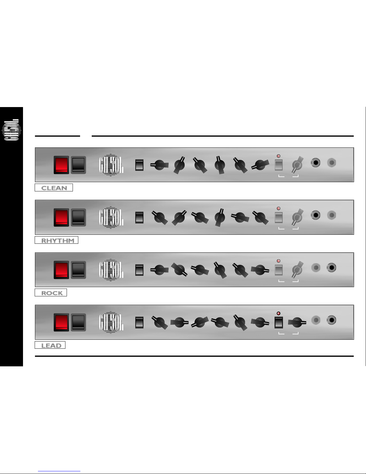
This manual has been written for easy access of information. The
front and rear panels are graphically illustrated, with each control
and feature numbered. For a description of the function of each
control feature, simply check the number with the explanations
adjacent to each panel.
Your Laney amplifier has undergone a thorough two stage, pre-
delivery inspection, involving actual play testing.
When you first receive your Laney guitar amplifier, follow these
simple procedures:
(i) Ensure that the amplifier is the correct voltage for the country
it is to be used in.
(ii) Connect your instrument with a high quality shielded
instrument cable. You have probably spent considerable money on
your amplifier and guitar - don’t use poor quality cable it won’t do
your gear justice.
Please retain your original carton and packaging so in the unlikely
event that some time in the future your amplifier should require
servicing you will be able to return it to your dealer securely
packed.
Care of your Laney amplifier will prolong it's life.....and yours!
EARTH or GROUND GREEN/YELLOW
NEUTRAL - BLUE
LIVE - BROWN
Laney
CAUTION:
WARNING:
Intended to alert the user to the presence of uninsulated ‘Dangerous Voltage’ within the products
enclosure that may be sufficient to constitute a risk of electrical shock to persons.
Ce symbole est utililise pur indiquer a l’utilisateur de ce produit de tension non-isolee dangereuse
pouvant etre d’intensite suffisante pour constituer un risque de choc electrique.
Este simbolo tiene el proposito de alertar al usuario de la presencia de ‘(voltaje) peligroso’ que no
tiene aislamiento dentro de la caja del producto que puede tener una magnitud suficiente como
para constituir riesgo de corrientazo.
Dieses Symbol soll den Anwender vor unsolierten gefahrlichen Spannungen innerhalb des
Gehauses warnen, die von Ausrichender Starke sind, um einen elektrischen Schlag verursachen
zu konnen.
Intended to alert the user of the presence of important operating and maintenance (Servicing)
instructions in the literature accompanying the product.
Dieses Symbol soll den Anwender vor unsolierten gefahrlichen Spannungen innerhalb des
Gehauses warnen, die von Ausrichender Starke sind, um einen elektrischen Schlag verursachen
zu konnen.
Este simbolo tiene el proposito de la alertar al usario de la presencis de instrucccones importantes
sobre la operacion y mantenimiento en la literatura que viene conel producto.
Dieses Symbol soll den Benutzer auf wichtige Instruktionen in der Bedienungsanleitung
aufmerksam machen, die Handhabung und Wartung des Produkts betreffen.
Risk of electrical shock - DO NOT OPEN.
To reduce the risk of electrical shock, do not remove the cover. No user serviceable parts inside.
Refer servicing to qualified personnel.
Risques de choc electrique - NE PAS OUVIRIR
Afin de reduire le risque de choc electrique, ne pas enlever le couvercle. II ne se trouve a l’interieur
aucune piece pouvant etre reparee par l’utilisateur. Confier l’entretien a un personnel qualifie.
Riesgo de corrientazo - no abra
Para disminuir el risego de carrientazo, no abra la cubierta. No hay piezas adentro que el pueda
reparar. Deje todo mantenimiento a los tecnicos calificadod.
Risiko - Elektrischer Schlag! Nicht offen!
Um das Risiko eines elektrischen Schlages zu vermeiden, nicht die Abdeckung enfernen. Es
befinden sich keine Teile darin, die vom Anwender repariert werden Konnten. Reparaturen nur von
qualifiziertem Fachpersonal durchfuhren lassen.
To prevent electrical shock or fire hazard, do not expose this appliance to rain or moisture. Before
using this appliance please read the operating instructions for further warnings.
Afin de prevenir les risques de decharge electrique ou de feu, n’exposez pas cet appareil a la pluie
ou a l’humidite. Avant d’utiliser cet appareil, lisez les advertissments supplentaires situes dans le
guide.
Para evitar corrientazos o peligro de incendio, no deja expuesto a la lluvia o humedad este
aparato Antes de usar este aparato, lea mas advertcias en la guia de operacion.
Um einen elektrischen Schalg oder Feuergefahr zu vermeiden, sollte dieses Gerat nicht dem
Regen oder Feuchtigkeit ausgesetzt werden. Vor Inbetriebnahme unbedingt die
Bedienungsanleitung lesen.
PRECAUCION:
ADVERTENCIA:
ATTENTION:
ADVERTISSEMENT:
VORSICHT:
ACHTUNG:
Page
3 / 16
Page
4 / 16
INTRODUCTION
Laney
INTRODUCTION
The GH50L is a single channel master volume style head with footswitchable gain, it is capable of a huge variety of sounds, from sparkling
clean through powerful crunch to full on monster tones and everything in between. The hand wired 50W output stage oozes classic, warm
tube tones: The harder you drive it, the better it sounds. The GH50L is designed to be used with the GS412IA and GS412IS cabinets - to
enhance the amplifiers huge tonal range and produce stunning tone at any volume.
Your GH50L should give you years of trouble-free amplification, however please take time to read this manual and familiarise yourself with the
controls as it will allow you to get the best from your amplifier. We hope you enjoy using your GH50L as much as we enjoyed designing and
making it.
Best wishes from all at Laney.
Dear Player,
Thank you very much for purchasing your new Laney product and becoming part of the worldwide Laney family. Each and every Laney unit is
designed and built with the utmost attention to care and detail, so I trust yours will give you many years of enjoyment.
Laney products have a heritage which stretches back to 1967 when I first began building valve amplifiers in my parent’s garage. Since then we
have moved on from strength to strength developing an extensive range of guitar, bass, public address and keyboard amplification products
along with a list of Laney endorsees that includes some of the world’s most famous and respected musicians. At the same time we believe we
have not lost sight of the reason Laney was founded in the first place - a dedication to building great sounding amplification for working
musicians.
Warm Regards,
Lyndon Laney CEO
Laney
Page
5 / 16
HI INPUT:
LO INPUT: ‘
.
: It is useful to experiment with the gain and volume controls. If
you want a very open, warm and semi overdriven sound try reducing the amount of gain and increasing the volume. This reduces pre
amp gain but pushes the power amp section and makes it work harder giving you a very desirable level of power amp distortion which
is a very pleasing “retro” style sound.
‘Hi’ stands for high gain. This input is designed for the connection of low output level guitars making it well suited for
guitars with single coiled or low gain humbucker type pickups. Use of high gain pickups in this input may drive the preamp too hard
causing a "mushy" sound. Only use good quality guitar cable.
Lo’ stands for low gain. This input is attenuated down approximately 50% from the Hi input and is designed for high
output level guitars. It is useful in obtaining output that is "tight" not "mushy" from high gain humbucker type pickups Also use this
input for the cleanest full range sound with extended low end response. Only use good quality guitar cable.
GAIN: Sets the level of tube preamplifier gain or how dirty your sound is. This control should be used in conjunction with the
Master Volume (4) Setting low levels of gain with high levels of volume will give a clean preamplifier sound with tube output stage
overdrive. Setting a medium gain level and medium Master Volume will give a nice crisp bluesy lead tone, again with the ability to drive
the output stage at higher Volume settings. Setting a high level on the Drive control and a low setting on the Drive Volume will give
you a punchy hard rock lead tone, with the ability to again drive the output tubes at higher Volume settings. Having set the Drive and
Drive Volume controls to your desired sound try backing off your guitar volume and tone controls for lots of other cool sounds.
Good tube amplifiers have the unique ability to produce a wide range of sounds by using only your guitar controls, playing weight and
style.
MASTER VOLUME Sets the overall ‘loudness’ of the amplifier.
-
FRONT PANEL CONTROLS
1122
5
4
3
2
1
010
9
8
7
65
4
3
2
1
010
9
8
7
65
4
3
2
1
010
9
8
7
65
4
3
2
1
010
9
8
7
65
4
3
2
1
010
9
8
7
65
4
3
2
1
010
9
8
7
65
4
3
2
1
010
9
8
7
6
PRESENCE BASS MIDDLE TREBLE MASTER VOLUME GAIN DRIVE
POWER STANDBY
1
0
HILO
RESONANCE INPUT
55
3344667788991010111113131414 1212
11
22
33
44
Page
6 / 16
Laney
DRIVE SWITCH: Switch in to enable the extra 'Drive' tube stage. This gives you even more gain to play around with. (This
switch must be in the engaged position in order for the drive to be switched remotely via a foot switch.)
DRIVE: This sets the amount of ‘Drive’ sound provided by the extra tube stage. This varies from subtle crunch to hi-gain lead
break sounds.
DRIVE LED: This led will illuminate when the extra drive stage is switched in.
BASS, MIDDLE, TREBLE: These are a traditional set of passive tone controls. Passive controls have the advantage of always
sounding musical at any of their settings mainly due to their unique interactive nature. This gives players a more natural set of tools to
create their ideal sound. (Try them all set at midway (5) as a good starting point)
PRESENCE: An output stage tone control. This adjusts the high frequency response - it adjusts your sound from being dull to
giving it edge / sounding sparkly.
RESONANCE: Adjusts level of Power Tube damping. This allows the player to adjust how tight the bass response is - this will be
dependent on what speaker cabinet used. The Resonance allows you to adjust the bass damping to your particular taste.
STANDBY: Disconnects the HT supply from the Tubes whilst the heaters still keep them warm. This allows you to switch out of
standby and play without waiting for your amplifier to warm up. This is useful after you have sound checked and you are waiting to go
on stage - leave the amp in standby so its ready to go when performance time comes. Always switch off for short breaks when you
don’t want to wait for the tubes to warm up again.
POWER: Main power switch for the unit. The GH50L features delay turn on circuitry to increase tube life, the HT supply to the
tubes gets switched on only after they have warmed up and are ready to go - approx 30 seconds.
(Always switch off and disconnect the power cord when not in use)
66
77
1111
1313
1414
1212
55
881010
-
FRONT PANEL CONTROLS - CONTINUED
Laney
Page
7 / 16
REAR PANEL CONTROLS
11
22
33
POWER INLET SOCKET: Connect to your power source. Make sure the specified voltage is correct for your country!
POWER FUSE: This is the main safety fuse for the unit. The fuse protects the AC power to the amplifier. USE ONLY THE
CORRECT SIZE AND RATING OF FUSE AS SPECIFIED ON THE PANEL. If a fuse blows or fails and a replacement of the same size
and rating is installed and it in turn blows, the amplifier has suffered a malfunction internally and needs immediate service from a
qualified technician. DO NOT TRY USING A FUSE OF HIGHER RATING. Using a fuse that is too large in current rating may cause
serious, irreparable damage to the amplifier and presents a serious fire hazard. The mains fuse ratings are detailed in the specs section
at the rear of this manual
HT FUSE: This fuse protects the DC power to the tubes within the amplifier. USE ONLY THE CORRECT SIZE AND RATING
FUSE AS SPECIFIED ON THE PANEL. If a fuse blows or fails and a replacement of the same size and rating is installed and it in turn
blows, the amplifier has suffered a malfunction, at this point check the output tubes and replace faulty ones if required. Should tubes
not be the problem the amplifier should be checked out by a qualified technician. Do not try using a fuse of greater value. Using a
fuse that is too large in current rating may cause serious, irreparable damage to the amplifier. Fuses are designed to protect, do not
take chances.
LOUDSPEAKERS: Loudspeaker outlets are provided on a series of five jack sockets. The impedance of the
loudspeaker/s should be checked and connected to the appropriate socket/s. Using the incorrect sockets will reduce the life of your
output tubes and won’t sound as good and in extreme cases could damage your amplifier.
IMPORTANT: Operation of your GH50L amplifier without a loudspeaker connected could result in expensive failure of your
output transformer. DO NOT OPERATE WITHOUT A LOUDSPEAKER CONNECTED.
There are dedicated optimised outputs for the following loudspeaker combinations:
1*16 ohm, 1*8 ohm, 2*16 ohm, 1*4 ohm, 2*8 ohm.
¼” (6.3mm)
CAUTION
RISK OF ELECTRIC SHOCK DO NOT OPEN
SUPPLY VOLTAGE
HT FUSE
CAUTION
TO REDUCE THE RISK OF FIRE REPLACE
ONLY WITH SAME TYPE AND RATING
MODEL : GH50L
SERIAL NO.
1*16 OHM
MAXIMUM POWER CONSUMPTION
300 WATTS
CAUTION - TO REDUCE THE RISK OF
ELECTRIC SHOCK, DO NOT REMOVE
COVER. NO USER SERVICABLE PARTS
INSIDE. REFER SERVICING TO
QUALIFIED SERVICE PERSONEL.
WARNING - THIS APPARATUS MUST
BE EARTHED
WARNING - TO REDUCE THE RISK OF
FIRE OR ELECTRIC SHOCK,
DO NOT EXPOSE THIS APPLIANCE TO
RAIN OR MOISTURE.
ATTENTION REMPLACER LE FUSIBLE
PR LE MEME ET CALIBRE
ATTENTION DEBRACHER A LA PRISE
SECTEUR AVANT D’OUVRIR
Laney N1646N1646
T1A L
MAINS FUSE
~220-240V = T2A L
~100-120V = T5A L
1*8 OHM 1*4 OHM
2*16 OHM 2*8 OHM
LOUDSPEAKERS
WARNING:
USE ONLY ONE IMPEDANCE
SELECTION AT A TIME
5881/6L6 EL34
FOOTSWITCH
BYPASS
SIDE/
CHAIN INSERT
SEND RETURN
5
4
3
2
1
010
9
8
7
6
FX RETURN
LEVEL
SLAVE IN SLAVE OUT BIAS
Made in the UK
www.laney.co.uk
SLAVE
PO W E R TO T HE M US IC
1616
771717 55
1515 1414 1313 1212 1111 1010 99886644332211
4488
-
REAR PANEL CONTROLS - CONTINUED
Page
8 / 16
Laney
BIAS: This allows you to bias the amplifier to suit your chosen output tubes. The switch has two positions 5881/6L6 and EL34. We
recommend the use of matched sets of output tubes for best performance. Ensure the switch is in the correct position otherwise you
risk damaging your amplifier.
SLAVE OUT: The slave out gives the user an output for driving other amplifiers. This is useful in multi-amp setups where a single
preamp can drive several GH power stages. This can be done by simply daisy chaining SLAVE OUT’s to SLAVE IN’s. The Slave Out is
an (unbalanced) line level output.
SLAVE IN: The Slave in socket provides the user with an input to the power amplifier stage. The Slave in is only operative when the
FX switch is in Side Chain or Insert mode. When a Jack is connected to the Slave In socket the preamp signal does not pass to the
power amp.
FX RETURN LEVEL: This control serves two purposes.
1) In Side chain mode it controls the level of the FX Return signal mixed with the dry signal.
2) In Insert mode it behaves as an overall level control. (See 14)
EFFECTS LOOP RETURN: Connect the output from your external effects to this socket. The effects loop allows you to
connect external effects such as tremolos, chorus and delays to your amplifier. A portion of the signal leaves the amplifier via the
`Send’ socket and comes back from the effects unit via the ‘Return’ socket. A notable feature on the GH products is you won’t lose
sustain when the FX loops are in use. This is because the power stages are still driven by a tube FX loop buffer.
EFFECTS LOOP SWITCH: This allows the effects loop to operate in three distinct modes:
1) Side Chain: The return signal is mixed with the dry signal, the level of FX return is controlled by the FX return level control. This
allows you to set the right mix between the dry signal and the effects signal. (When the Effects loop switch is in ‘Side Chain’ mode the
Slave in socket is operative)
2) Insert: The return signal is buffered and sent directly to the output tubes, no mixing with the dry signal happens. The wet/dry mix
is adjusted within the external FX processor. The FX return level control then acts as overall level control allowing you to make up for
any insertion loss that may occur in the FX processor. Warning: In insert mode with the FX return level control at minimum the
amplifier will have no output, good normal level for this control is ‘5’ which is approx unity gain. (When the Effects loop switch is in
‘Insert’ mode the Slave In socket is operative)
3) Bypass: The FX loop circuitry is switched out of circuit altogether.
99
1010
1111
1313
1414
1212
Laney
Page
9 / 16
1616
1717
1515 EFFECTS LOOP SEND: Connect the input of your external effect to this socket. A ‘side chain’ effects loop allows you to
connect external effects such as tremolo’s, chorus and delays to your amplifier. Signal leaves the amplifier via the `Send’ socket and
comes back from the effects via the `Return` socket. Some Effects are better suited to being between the guitar and amplifer input -
these are foot pedal types / distortion / wah wah pedals etc. Rack mount effects will work better in the FX loop on the amplifer rear.
Stomp boxes are normally designed for small signals such as a guitar output whereas rack mount FX are designed for the higher signal
level obtained from an FX send.
FOOTSWITCH: Connect a Laney FS1 footswitch here to allow remote switching of the front panel drive switch. The Drive
switch needs to be in the ON position for the footswitch to operate. The footswitch shorts the tip + ring together on a mono jack.
SERIAL NO: Displays the model and serial number of the unit.
BLOCK DIAGRAM
HI INPUT
1*16 Ohm
FX RETURN
FX SEND
FOOTSWITCH
LO INPUT
PAD
DRIVE
GAIN
FX RETURN
V1a
V1b
V4a
V4b
V5
V6
8Ohms
4Ohms
EQEQ
BASS
MID
TREBLE
V2a V2B V3a
MASTER
VOLUME
BYPASS
INSERT
SIDE
CHAIN
V3B
SLAVE IN
SLAVE OUT
16Ohms
LOUDSPEAKERS
2*16 Ohm
1*8 Ohm
2*8 Ohm
1*4 Ohm
BIAS
5881/6L6
EL34
RESONANCE
PRESENCE
Page
10 / 16
QUICK START SETTINGS - suggestions only, experiment!
Laney
5
4
3
2
1
010
9
8
7
6
5
4
3
2
1
010
9
8
7
6
5
4
3
2
1
010
9
8
7
6
5
4
3
2
1
010
9
8
7
6
5
4
3
2
1
010
9
8
7
6
5
4
3
2
1
010
9
8
7
6
5
4
3
2
1
010
9
8
7
6
5
4
3
2
1
010
9
8
7
6
5
4
3
2
1
010
9
8
7
6
5
4
3
2
1
010
9
8
7
6
5
4
3
2
1
010
9
8
7
6
5
4
3
2
1
010
9
8
7
6
5
4
3
2
1
010
9
8
7
6
5
4
3
2
1
010
9
8
7
6
5
4
3
2
1
010
9
8
7
6
5
4
3
2
1
010
9
8
7
6
5
4
3
2
1
010
9
8
7
6
5
4
3
2
1
010
9
8
7
6
5
4
3
2
1
010
9
8
7
6
5
4
3
2
1
010
9
8
7
6
5
4
3
2
1
010
9
8
7
6
5
4
3
2
1
010
9
8
7
6
5
4
3
2
1
010
9
8
7
6
5
4
3
2
1
010
9
8
7
6
5
4
3
2
1
010
9
8
7
6
5
4
3
2
1
010
9
8
7
6
5
4
3
2
1
010
9
8
7
6
5
4
3
2
1
010
9
8
7
6
PRESENCE
PRESENCE
PRESENCE
PRESENCE
BASS
BASS
BASS
BASS
MIDDLE
MIDDLE
MIDDLE
MIDDLE
TREBLE
TREBLE
TREBLE
TREBLE
MASTER VOLUME
MASTER VOLUME
MASTER VOLUME
MASTER VOLUME
GAIN
GAIN
GAIN
GAIN
DRIVE
DRIVE
DRIVE
DRIVE
POWER
POWER
POWER
POWER
STANDBY
STANDBY
STANDBY
STANDBY
1
1
1
1
0
0
0
0
HI
HI
HI
HI
LO
LO
LO
LO
RESONANCE
RESONANCE
RESONANCE
RESONANCE
INPUT
INPUT
INPUT
INPUT
CLEAN
RHYTHM
ROCK
LEAD
ON