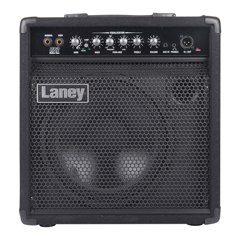
Laney RICHTER RBW100 User manual

Laney
RBW100
RBW200
RBW300
RBH700
RBH800
RBG400
RBG500

Laney
Care of your amplifier will prolong it's life.....andLaney
After unpacking your amplifier check that it is factory fitted with a three pin 'grounded' (or earthed) plug. Before
plugging into the power supply ensure you are connecting to a grounded earth outlet.
If you should wish to change the factory fitted plug yourself, ensure that the wiring convention applicable to the
country where the amplifier is to be used is strictly conformed to. As an example in the United Kingdom the cable
colour code for connections are as follows.
EARTH OR GROUND - GREEN/YELLOW
NEUTRAL - BLUE
LIVE - BROWN
Congratulations on your decision to purchase a amplifier.
products are designed with ease of operation as a primary objective, however to ensure you derive the best
from your new amplifier, it is important you take time to read this user manual and to familiarise yourself with the
control functions and facilities available
Laney
Laney
INTRODUCTION
BEFORE
SWITCHING ON
This manual has been written for easy access of information. The front and rear panels of each unit are
graphically illustrated, with each control and feature numbered. For a description of the function of each control
feature, simply check the number with the explanations adjacent to each panel.
Your bass amplifier has undergone a thorough two stage, pre-delivery inspection, involving
actual play testing, as well as burn in.
Laney RICHTER
When you first recieve your bass amp, follow these simple procedures:
(i) Ensure that the amplifier is set at the correct voltage for the country it is to be used in.
(ii) Connect your instrument with a high quality shielded instrument cable. Use of cheap cables will compromise
the sound of your instrument and your amplifier.
Laney RICHTER
If there is a problem with your bass amplifierLaney RICHTER
DON'T DO
PHONE YOUR DEALER!
1

Laney
2
COMP
3
INPUT
ACTIVE
10
0
GAIN
PASSIVE/
ACTIVE
9
8
7
6
5
4
3
2
1
GAIN
5
5
5
1K
100
BASS
FREQUENCY
2
4
-0+
1
-0+
1
4
3
2
1
2
3
4
PARAMID
500
5
10
5 5
0
VOLUME
TREBLE
8
7
1
6
4
3
2
1
2
3
4
4
3
2
1
-0+
5
4
3
2
1
9
PHONES
D.I.
0
RBW100
POWER
1
300WATTS ~50-60Hz
MAXIMUM POWER CONSUMPTION
&FUSERATING
SUPPLY VOLTAGE
THIS EQUIPMENT MUST BE EARTHED.
WARNING
SECTEUR AVAV T D ' OUVRIR.
DEBRANCHER A LA PRISE
TO QUALIFIED SERVICE PERSONNEL
PARTS INSIDE. REFER SERVICING
COVERS. NO USER SERVICABLE
OF ELECRIC SHOCK DO NOT REMOVE
TO REDUCE THE RISK
MADE IN THE UNITED KINGDOM BY BLT INDUSTRIES LTD.
MINIMUM 8 OHM
SPEAKER
EXTERNAL
~115V T5A
~230V T2A
ATTENTION
PAR LE MEME ET LE CALIBRE.
REMPLACER LE FUSIBLE
ATTENTION
SAME TYPE AND RATING ONLY.
FIRE HAZARD REPLACE FUSE WITH
TO REDUCE THE RISK OF
CAUTION
CAUTION
NOT EXPOSE THIS APPLIANCE TO
OF FIRE OR ELECTRIC SHOCK DO
SERIAL No:
TO REDUCE THE RISK
RAIN OR MOISTURE.
WARNING
CE
EFFECTS LOOP
SEND
TUNER
RETURN
FREQUENCY
500
PASSIVE/
ACTIVE ACTIVEACTIVE
INPUT
100
7 7
2
3
2
3
0
2
1
8 8
2
10
GAIN
COMP
9
5
5
10
0
ENHANCEENHANCE
BASS
4
9
1
4
3 3
4 6
5
6
5
4
1
-0+
1
RBW300
4
2
2
2
2 2
TREBLE
4
1K
3
5
GAIN
5 55
4K
400
5
FREQUENCY
GAIN
4 4
4
4
3 3
3
3
5
LO PARAMIDLO PARAMID
1
-0+
1 1
-0+
1
HI PARAMIDHI PARAMID
1K5
-0+
1 1
2
7
3
DEFEAT
LIMIT
3
82
HORN
10
0
VOLUME
9
1
D.I.
6
5
4
0
POWER
1
300WATTS ~50-60Hz
MAXIMUM POWER CONSUMPTION
&FUSERATING
SUPPLY VOLTAGE
THIS EQUIPMENT MUST BE EARTHED.
WARNING
SECTEUR AVAV T D ' OUVRIR.
DEBRANCHER A LA PRISE
TO QUALIFIED SERVICE PERSONNEL
PARTS INSIDE. REFER SERVICING
COVERS. NO USER SERVICABLE
OF ELECRIC SHOCK DO NOT REMOVE
TO REDUCE THE RISK
MADE IN THE UNITED KINGDOM BY BLT INDUSTRIES LTD.
MINIMUM 8 OHM
SPEAKER
EXTERNAL
~115V T5A
~230V T2A
ATTENTION
PAR LE MEME ET LE CALIBRE.
REMPLACER LE FUSIBLE
ATTENTION
SAME TYPE AND RATING ONLY.
FIRE HAZARD REPLACE FUSE WITH
TO REDUCE THE RISK OF
CAUTION
CAUTION
NOT EXPOSE THIS APPLIANCE TO
OF FIRE OR ELECTRIC SHOCK DO
SERIAL No:
TO REDUCE THE RISK
RAIN OR MOISTURE.
WARNING
CE
EFFECTS LOOP
SEND
TUNER
RETURN
RBW300 rear
RBW300/RBH700/RBH800 front
RBW100 rear
RBW200 rear
FREQUENCY
100
ACTIVE ACTIVE
PASSIVE/
INPUT
GAIN
4
3
2
1
0
5
BASS
10
9
8
7
6
-0+
1
2
3
4
5
10
9
8
7
6
5
4
3
2
1
0
COMP
ENHANCE
5
4
3
2
1
RBW200
LIMIT
DEFEAT
PRESENCE
9
7
500
10
3
PARAMID
1K
5
4
3
2
1
-0+
1
2
3
4
5 5
4
3
2
1
-0+
1
2
3
4
5
2
GAIN
TREBLE
6
5
4
1
0
8
10
9
8
7
6
5
4
3
2
1
0
VOLUME
HORN
D.I.
POWER
1
0
RBW200 front
CAUTION
ELECRIC SHOCK DO NOT REMOVE
COVERS. NO USER SERVICABLE
PARTS INSIDE. REFER SERVICING
TO QUALIFIED SERVICE PERSONNEL
TO REDUCE THE RISK OF
FIRE HAZARD REPLACE FUSE WITH
SAME TYPE AND RATING ONLY.
REMPLACER LE FUSIBLE
PAR LE MEME ET LE CALIBRE.
MADE IN THE UNITED KINGDOM BY BLT INDUSTRIES LTD.
SUPPLY VOLTAGE
~115V T2A~115V T2A
& FUSE RATING
~230V T1A
WARNING
MAXIMUM POWER CONSUMPTION
140 WATTS ~ 50 - 60 Hz
CAUTION
ATTENTION
THIS EQUIPMENT MUST BE EARTHED.
NOT EXPOSE THIS APPLIANCE TO
RAIN OR MOISTURE.
WARNING
TO REDUCE THE RISK
OF FIRE OR ELECTRIC SHOCK DO
DEBRANCHER A LA PRISE
SERIAL No:
TO REDUCE THE RISK OF
ATTENTION
SECTEUR AVAV T D ' O U VRIR.
CE
SEND
RETURN
EFFECTS LOOP
RBW100 front

Laney
3
COMP
3
INPUT
ACTIVE
10
0
GAIN
PASSIVE/
ACTIVE
9
8
7
6
5
4
3
2
1
GAIN
5
5
5
1K
100
BASS
FREQUENCY
2
4
-0+
1
-0+
1
4
3
2
1
2
3
4
PARAMID
500
5
10
5 5
0
VOLUME
TREBLE
8
7
1
6
4
3
2
1
2
3
4
4
3
2
1
-0+
5
4
3
2
1
9
PHONES
D.I.
0
RBW100
POWER
1
RBW100 front
6
123 4 7 8 9
5 10
Active and Passive/Active Inputs:
Gain:
Compressor:
Bass:
Paramid-Frequency:
Paramid-Gain:
Treble:
Volume:
Direct Inject:
Phones:
FX Loop:
Tuner out:
Horn switch:
ACTIVE and PASSIVE/ACTIVE inputs are provided for
connection of bass guitars. Active basses should be connected via the ACTIVE socket. Non
active basses should be connected using the passive input. Active basses may also be placed in
the PASSIVE input if pre-amp overloading is desired.
This control is used to set the level of gain present in the pre-amp. The higher the level of
gain, the more the signal will clip producing distortion. The GAIN control should be used in
conjunction with the VOLUME control (8) to produce the desired signal characteristics.
Engages and disengages the on-board COMPRESSOR. This compresses the
input-signal giving a punchier sound.
Controls the low-frequency response of the pre-amplifier.
Selects the MID-frequencies to be cut or boosted in conjunction with the
PARAMID GAIN control (6). To access LO mid-frequencies turn the FREQUENCY control
anticlockwise, to access HI mid frequencies turn the FREQUENCY control clockwise.
Sets the level of boost or cut applied to the frequency set by control 5. For
frequency-boost turn the control clockwise. For frequency-cut, turn the control anti-clockwise.
Controls the high-frequency response of the pre-amplifier.
Sets the overall listening level of the amplifier.
XLR socket for direct-injection of the amplifier signal to a mixing-desk or additional
power-amplifier. The XLR socket provides a low-impedance output-signal.
Headphone output for silent practicing.
Send and return sockets are provided for connecting external effects-units.
Socket for connecting external tuner.
Switches the on-board horn either on or off.
6.Paramid Gain:
1.Inputs:
2.Gain:
3.Compressor:
13.Horn switch:
5.Paramid frq:
4.Bass:
7.Treble:
8.Volume:
9.D.I:
CAUTION
ELECRIC SHOCK DO NOT REMOVE
COVERS. NO USER SERVICABLECOVERS. NO USER SERVICABLE
PARTS INSIDE. REFER SERVICINGPART S INSIDE. REFER SERVICING
TO QUALIFIED SERVICE PERSONNELTO QUALIFIED SERVICE PERSONNEL
TO REDUCE THE RISK OFTO REDUCE THE RISK OF
FIRE HAZARD REPLACE FUSE WITHFIRE HAZARD REPLACE FUSE WITH
SAME TYPE AND RATING ONLY.SAME TYPE AND RATING ONLY.
REMPLACER LE FUSIBLEREMPLACER LE FUSIBLE
PAR LE MEME ET LE CALIBRE.PAR LE MEME ET LE CALIBRE.
MADE IN THE UNITED KINGDOM BY BLT INDUSTRIES LTD.MADE IN THE UNITED KINGDOM BY BLT INDUSTRIES LTD.
SUPPLY VOLTAGESUPPLY VOLTAGE
~115V T2A~115V T2A
& FUSE RATING& FUSE RATING
~230V T1A~230V T1A
WARNING
MAXIMUM POWER CONSUMPTIONMAXIMUM POWER CONSUMPTION
140 WATTS ~ 50 - 60 Hz140 WATTS ~ 50 - 60 Hz
CAUTION
ATTENTION
THIS EQUIPMENT MUST BE EARTHED.THIS EQUIPMENT MUST BE EARTHED.
NOT EXPOSE THIS APPLIANCE TONOT EXPOSE THIS APPLIANCE TO
RAIN OR MOISTURE.RAIN OR MOISTURE.
WARNING
TO REDUCE THE RISKTO REDUCE THE RISK
OF FIRE OR ELECTRIC SHOCK DOOF FIRE OR ELECTRIC SHOCK DO
DEBRANCHER A LA PRISEDEBRANCHER A LA PRISE
SERIAL No:
TO REDUCE THE RISK OFTO REDUCE THE RISK OF
ATTENTION
S E C T E U R AVAV T D ' O U V R I R .
CE
SENDSEND
RETURN
EFFECTS LOOPEFFECTS LOOP
RBW100 rearRBW100 rear
13
11 12
10.Phones:
11.FX loop:
12.Tuner out:
Laney
4
Enhance:
Presence:
Limiter Defeat:
External speaker socket:
The ENHANCE control provides an increased definition at the low-end of the
frequency spectrum giving you a tighter, punchier sound. The ENHANCE control does this
by providing a dip in the frequency-response of the amplifier at approximately 200hz. This
dip eliminates some of the secondary-harmonics of the important low-frequencies around
40-80 Hz producing a thicker sound. Turning the control through to its maximum has the
effect of boosting both the low and high-frequency content of the signal whilst not effecting
the mids.
Controls the high-frequency signal-content of the pre-amplifier. The PRESENCE
control is set at 3K.
Allows the on-board LIMITER to be defeated if desired. With the switch in
the out position the LIMITER is engaged. The LIMITER is automatically triggered at high-
output levels and is designed to prevent power-amp distortion at high-output levels. The
LIMITER monitors both power-amp clipping and load so it automatically registers the
cabinet-impedance and sets itself accordingly.
This socket should be used to connect an extension-cabinet.
The impedance of the extension-cabinet must not be less the 8 Ohms. Connecting
cabinets that have a lower impedance than 8 Ohms will result in the amplifier overheating;
continual use in this manner may cause permanent damage. Connecting a cabinet with an
impedance of greater than 8 Ohms will cause no damage to the amplifier but will result in a
reduced output.
Laney
15
15.Presence:
300WATTS ~50-60Hz300 WATTS ~ 50 - 60 Hz
MAXIMUM POWER CONSUMPTIONMAXIMUM POWER CONSUMPTION
&FUSERATING& FUSE RATING
SUPPLY VOLTAGE
THIS EQUIPMENT MUST BE EARTHED.THIS EQUIPMENT MUST BE EARTHED.
WARNING
SECTEUR AVAV T D ' OUVRIR.SECTEUR AVAVT D'OUVRIR.
DEBRANCHER A LA PRISEDEBRANCHER ALA PRISE
TO QUALIFIED SERVICE PERSONNELTO QUALIFIED SERVICE PERSONNEL
PARTS INSIDE. REFER SERVICING
COVERS. NO USER SERVICABLECOVERS. NO USER SERVICABLE
OF ELECRIC SHOCK DO NOT REMOVEOF ELECRIC SHOCK DO NOT REMOVE
TO REDUCE THE RISKTO REDUCE THE RISK
MADE IN THE UNITED KINGDOM BY BLT INDUSTRIES LTD.MADE IN THE UNITED KINGDOM BY BLT INDUSTRIES LTD .
MINIMUM 8 OHMMINIMUM 8 OHM
SPEAKER
EXTERNAL
~115V T5A
~230V T2A
ATTENTION
PAR LE MEME ET LE CALIBRE.PAR LE MEME ET LE CALIBRE.
REMPLACER LE FUSIBLEREMPLACER LE FUSIBLE
ATTENTIONATTENTION
SAME TYPE AND RATING ONLY.SAME TYPE AND RATING ONLY.
FIRE HAZARD REPLACE FUSE WITHFIRE HAZARD REPLACE FUSE WITH
TO REDUCE THE RISK OFTO REDUCE THE RISK OF
CAUTIONCAUTION
CAUTION
NOT EXPOSE THIS APPLIANCE TONOT EXPOSE THIS APPLIANCE TO
OF FIRE OR ELECTRIC SHOCK DOOF FIRE OR ELECTRIC SHOCK DO
SERIAL No:SERIAL No:
TO REDUCE THE RISKTO REDUCE THE RISK
RAIN OR MOISTURE.RAIN OR MOISTURE.
WARNING
CE
EFFECTS LOOPEFFECTS LOOP
SEND
TUNER
RETURN
RBW200/RBW300 rear
FREQUENCY
100
ACTIVE ACTIVE
PASSIVE/
INPUT
GAIN
4
3
2
1
0
5
BASS
10
9
8
7
6
-0+
1
2
3
4
5
10
9
8
7
6
5
4
3
2
1
0
COMP
ENHANCE
5
4
3
2
1
RBW200
LIMIT
DEFEAT
PRESENCE
9
7
500
10
3
PARAMID
1K
5
4
3
2
1
-0+
1
2
3
4
5 5
4
3
2
1
-0+
1
2
3
4
5
2
GAIN
TREBLE
6
5
4
1
0
8
10
9
8
7
6
5
4
3
2
1
0
VOLUMEVOLUME
HORN
D.I.
POWER
1
0
RBW200 front
16
16.Limiter:
17.Spkr. socket:
14.Enhance:
17
RBW300/RBH700/RBH800 front
8
FREQUENCY
500
ACTIVEACTIVE ACTIVE
INPUT
100
7 7
2
3
2
3
0
2
1
8 8
2
10
GAIN
COMP
9
5
5
10
0
ENHANCEENHANCE
BASS
4
9
1
4
3 3
4 6
5
6
5
4
1
-0+
1
RBW300
4
2
2
2
2 2
TREBLE
4
1K
3
5
GAIN
5 55
4K
400
5
FREQUENCY
GAIN
4 4
4
4
3 3
3
3
5
LO PARAMIDLO PARAMID
1
-0+
1 1
-0+
1
HI PARAMIDHI PARAMID
1K5
-0+
1 1
2
7
3
DEFEAT
LIMIT
3
82
HORN
10
0
VOLUME
9
1
D.I.
6
5
4
0
POWER
1
13 9
16
6
14
127
4 7 8
11
5
12
14
12314
123
319 20 21
18
4
PASSIVE/

Line Out:
Hi and Lo Preshapes:
Graphic EQ:
Full, Bright & Horns:
Socket for providing a line-level-signal-source for connecting to an additional
external power-amplifier.
There are two factory-determined EQ settings which can be used as
building-blocks in conjunction with the onboard graphic-EQ (25) to achieve individual tone. The
HI button adds boost to the high-end of the frequency spectrum whilst the LO button adds
additional low-end boost to the signal.
The 6-band onboard GRAPHIC-EQ allows extensive tonal-shaping to be
achieved. With the sliders along the centre-line the GRAPHIC-EQ will exert a flat signal-
response; it is at this point that individual frequency-bands can be cut or boosted. Moving the
slider beneath the centre-line will incur a frequency-cut; conversely, pushing the slider above
the centre-line facilitates frequency-boost. As a general rule, avoid extreme settings of the
sliders: try to set the GRAPHIC with as little cut or boost as possible.
The FULL button engages a speaker-control function that produces a
pronounced, tighter bottom-end. The BRIGHT button adds an increased attack and sparkle to
the upper frequencies present in the amplifier. The HORNS switch engages or disengages the
onboard horns.
Laney
5
26. Full, Bright &
Horns EQ:
Laney
23.Line out:
24. Pre shapes:
25. Graphic EQ:

WARNING: To prevernt electrical shock or fire hazard, do not expose this appliance to rain or moisture. Before using this
appliance, read the operating guide for further warnings.
Caution:
Caution:
Risk of electrical shock - DO NOT OPEN!
To reduce the risk of electrical shock, do not remove cover. No user servicable parts inside. Refer servicing to
qualified service personnel.
Intended to alert the user to the presence of uninstalled "dangerous voltage" within the product's enclosure
that may be of sufficient magnitude to constitute a risk of electric shock to persons.
Intended to alert the user of the presence of important operating and maintenance (servicing) instructions in
the literature accompanying the product.
This apparatus must be earthed. The wires in these mains are coloured in accordance with the following code.
Green & Yellow Earth Blue Neutral Brown Live
As the colours of the wires in the mains lead of this appliance may not correspond with the coloured markings identifying
the terminals in your plug, proceed as follows: - The wire which is coloured GREEN & YELLOW must be connected to
the terminal in the plug which is marked with the letter E or by the earth symbol or coloured green or Green and yellow.
The wire which is coloured Blue must be connected to the terminal which is marked with the letter N or coloured BLACK.
The wire which is coloured BROWN must be connected to the terminal which is marked with the letter L or coloured RED.
If a 13 amp (BS1363) plug is used a 13-amp fuse must be fitted, or if any other type of plug is used a 15 amps fuse must be
fitted either in the plug or adapter or at the distribution board.
It is inherent in the design of a loudspeaker and in the design of guitar pickups that they should emit or be affected by electro
magnetic fields. Loudspeaker enclosures should not be used less than two meters away from equipment, which is likely to
be affected by electro magnetic interference.
Likewise, guitar fitted with electro magnetic pickups should not be used less than two meters away from any source of
emissions such as loudspeakers. Emissions from loudspeakers are dependent on the frequency characteristics of the drive
unit. Levels were measured direct from the driver of 30 dBuV. These levels are reduced to a safe level at a distance of 1,27
meters from the drivers.
EMC warning
Laney
6
Laney

BLT Industries Ltd.,
Newlyn Road,
Cradley Heath,
West Midlands.
B64 6BE.
Http://www.laney.co.uk
Tel: (0044) (0)1384 633821
Fax: (0044) (0)1384 639186
In the interest of continued product development BLT Industries Ltd. Reserves the
right to amend product specification wihtout prior notification.
This manual suits for next models
6
Table of contents
Other Laney Musical Instrument Amplifier manuals

Laney
Laney EA120 User manual

Laney
Laney Iommi TI15-112 User manual

Laney
Laney GH100TI User manual

Laney
Laney Richter Bass RB3 User manual

Laney
Laney LV100 User manual

Laney
Laney LA30C User manual

Laney
Laney LX120RTWIN User manual

Laney
Laney Iron heart User manual

Laney
Laney LC50-112 User manual

Laney
Laney LR20 User manual