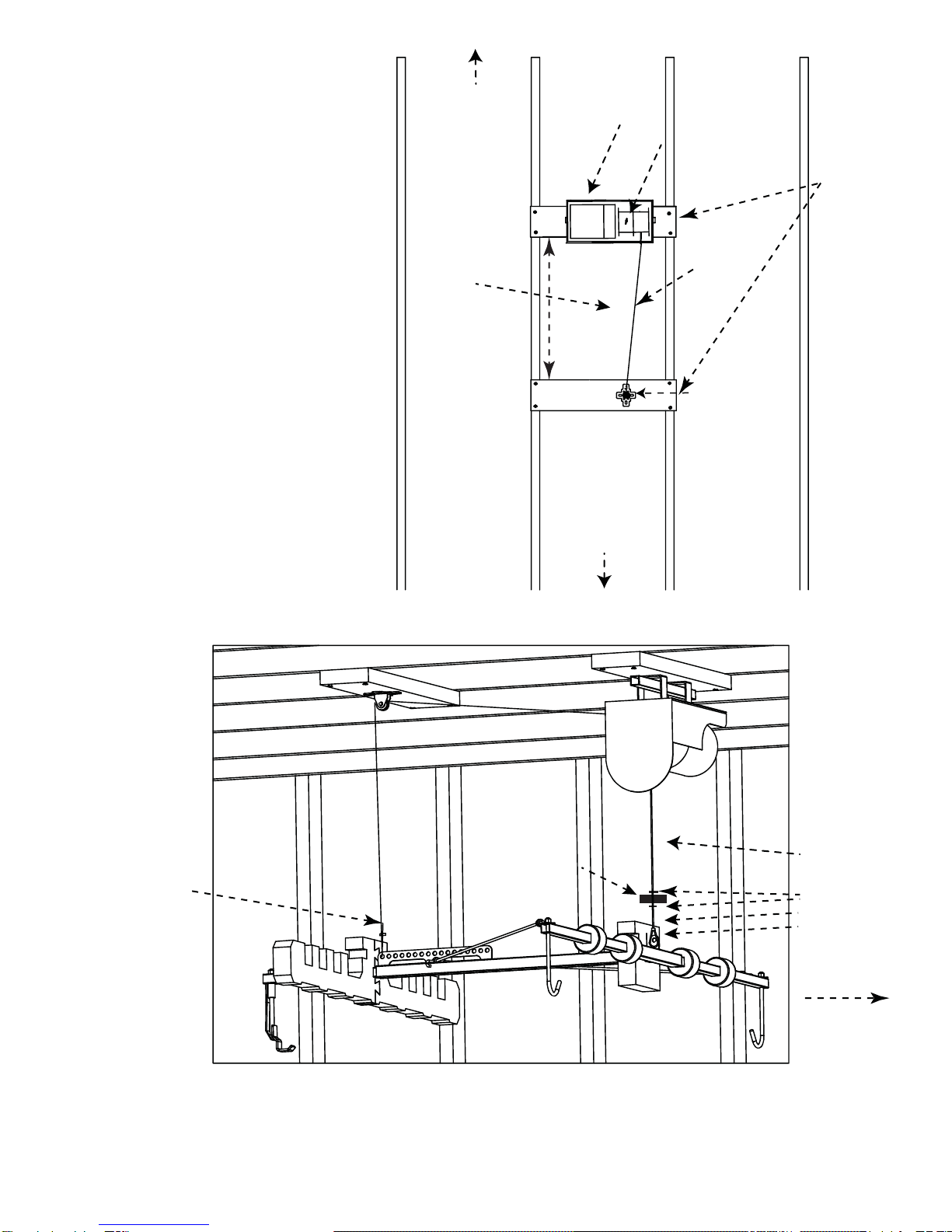
Lange Originals Hoist-a-Top User manual

TOP
A
HOIST ®
Power Installation Instructions
Hoistatop.com
Lange Originals
3651 S. 700 E.
Salt Lake City, UT
801-262-7322

Parts List
This list may include optional items, from other
Hoist-a-Top® systems, as well as a list of common parts
included in all hoists. Parts are listed by part number,
description, and quantity. The part number may be
referenced in the instructions designated by parenthesis
() for your convenience. Parts are updated periodically
and may have a dierent color or shape..
Part Number Description Qt
Common Parts (All systems have these parts)
1 Support Arms 3
2 “T” Section 1
3 Black Foam Holes 3
4 Plastic End Caps 3
5 “J” Hooks 2
6a Rear “Smart Hook™” JK only 1
6b Rear Hook for CJ/YJ/TJ only 1
7 Nyloc Nuts 3
9 Ceiling Pulley 2
10 Wood Screws for pulleys 9
11 Zinc Plated 3.5“ screws for lumber 14
Power Unit Additional Parts
1a 110V Winch 1
2a Large Eye-lag 1
3a Mounting Bar 1
4a 4” Lag Screws 2
5a Wire Clamps 8
6c 3/8“ Washer 2
7a Weighted Saftey Stop 2
8a 3/16” thimble 2
Optional Parts for JK Jeep Hoists 2007-2018
1d Black Foam Hole 1
2d Foam “T” Support 1
3d Long Foam Support Arms 2
4d Strap w/Grommets 2
5d Bungies 2
Optional Parts for JL Jeep Hoists 2018 and Newer
6d JL rear “Smart Hook™” 1
7d Wing Nut 1
1a
5a
3a
4a
6a JK only
10
8a
6b TJ/YJ/CJ only
7
4
7
1d
2d
6d 4d
3d
TOP
A
HOIST ®
9
11
1
2
7
3
5
6c
d
Page 1
PLEASE READ ALL INSTRUCTION BEFORE INSTALLATION
5d
7a
7d

Site Preparation
Determine whether to do a side wall mount, or a directly-over-hardtop ceiling
mount. The largest determining factor of this is ceiling height. Garages with 7-9 ft
ceiling it is recommended that a side wall installation is done. Garages over 9 ft tall it
is recommended that the power unit is installed in an overhead ceiling mount
conguration. If your ceiling is vaulted, or abnormal (anything other than parallel to
the oor) consult a contractor/professional, you will be required to build additional
supports for your power unit. Plug your power unit into a wall and test it up and
down while holding the cable centered in the fair-lead before beginning installation.
®
Lifting Cautions
Never lift your top so it is tight against the ceiling. This puts undue stress on the top and the hoist. Keep your body,
especially your hands away from edges of the top. We recommend you push or pull the top from the side and not
use the bottom edge. There is a natural tendency to align the top with your ngers under the edge.
Periodically check nuts and bolts on the Hoist-a-Top® system for tightness. Also, inspect the ceiling mounting points
for damage, or bent parts.
All Garages are dierent. Carefully read and watch the video and written instructions before installing. If you are
unsure or uncomfortable with installing this product contact a structural professional. Always test this mechanism
using a static and live load. Never stand, allow children, or pets under a lifted object on this mechanism. Misuse or
improper installation of this product can result in serious injury or death. Follow all safety rules and regulations of
tools and ladders while installing this product. Wear safety glasses, gloves, and boots while installing this product.
Never walk under or allow others to either play, stand, or work under the top.
If you need help or are missing a part DO NOT CALL YOUR DEALER. You will receive faster support though
the factory 1-866-284-7428 We oer technical support Monday through Friday 9:00 AM to 4:30 PM Mountain
Standard Time. Send us an inquiry via our website hoistatop.com anytime, or contact1@langeoriginals.com. No
question or problem is trivial so we'll try and help any way we can. We use these products ourselves and like them,
we hope you will too. Lange Originals® is not responsible for damage or personal injury due to improper installa-
tion, custom installation that doesn’t follow the instructions, or neglect.
There is an online video that is extremely helpful for this product. Most questions are answered visually by watching
us do it in the video. Scanning the QR codes will open an video menu page . You can also browse to langeinstruc-
tions.com. We also have a section in the video for removing the hard top latches and wiring etc. Which can be tricky
the rst couple of times.
Warranty: This product has a 1 year limited warranty from the invoice date of purchase for defective parts only.
Lange will repair or replace parts at their discretion. For full warranty information please see langeoriginals.com and
click on warranty, and nd your specic ordered part number. Valid invoice/receipt required.
Huh? What's this thing? It’s a QR code!
Scan it with your phone to get video help,
or additional instructions. Or go to:
www.langeinstructions.com
ORIGINALS
Lange Power Unit Installation Instructions
Tools needed: Safety glasses , gloves, screwdrivers, socket wrench set with driver and sockets, drill, stan-
dard drill bits, stud-nder, and chop saw/skill saw.
Installation Time: 1-3 hours depending on experience
Installation Diculty: 3 out of 5. Person should have a basic knowledge of common household tools and
be able to nd a wall stud without diculty. Specialized tools not required. Note that text underlined in
the installation guide is found in a glossary of terms in the back of the guide.
Page 2

Ceiling Mounting
Overhead mounting the power unit: To determine
a suitable lifting point from the ceiling, back your
Jeep in the garage to a suitable parking spot and
run a plumb-bob from the center of your hardtop
to the ceiling and make a mark with a pencil. Make
sure you still have room to open your tailgate.
Using a stud-nder or your preferred method
determine the closest stud/TJI set to your mark. Install
cross bracing appropriate to your garage conguration
(see Fig. b-e) Install the pulley on a separate 2x6 cross
brace using the 4 provided long wood screws. Install “U”
brackets on the back of the power unit using the provided bolts and lock
washers that are in your power unit box. Using a 15/64” drill bit, use your
mounting bar (3a) as a template to drill pilot holes into your cribbed cross
brace and install one side of the mounting bar fairly loosely with the lag bolt
(4a) and washer (6c). (With a helper )slide power unit onto the open side of
the mounting bar.
Thread the other lag bolt(4a) with washer (6c) through the mounting brack-
et hole, and into the pre-drilled wood cross brace. Alternate tightening
bolts until they are snug. Extend the cable to release some slack , thread
pulley cable (see Fig. e) through the hole in the casing and spool through the
oset pulley in the housing (see Fig. b-e). Leave the drop cable hanging down
toward the oor. We will go over attaching the frame and balancing in the
sections to follow.
Install one side of the mounting bar fairly loosely
with the lag bolt (4a). (With a helper )slide power
unit onto the open side of the mounting bar.
Scan here to access video
instructions page that
breaks down this section
or go to:
www.langeinstructions.com
Page 3

With the mounng
lag screws (4a) provided,
mount the mounng bar (3a)
to one 2x6 and one of the
single pulleys in the
center of another 2x6.
Mount the pulley offset
so it lines up with the
drop cable otherwise
the frame will not center
properly.
Power Unit
Oset Pulley
Drop cable
Drop cable
Shown as if
looking up at
the ceiling with
bare studs/joists
2x6
Cribbing
Determine if your studs run
perpendicular or Parallel with
your garage door. If your
studs run perpendicular to
(or the opposite direction as
your garage door).
Ceiling mount
with perpendicular studs
Center point
measured with
plumb bob
Center the two 2x6 ‘s
between the area you
marked with the plumb
bob (center of your hard
top measured from the
ceiling down.) 2 X 6
boards are 27 inches
apart.
Back wall or garage door
Fig. c
Fig. b
Safety Stop
Cable
clamps (5a)
3 x Cable
clamps (5a)
Garage door
Pulley cable
(7a)
Page 4
27
In
c
h
es

Oset Pulley
Shown as if
looking up at
the ceiling with
bare studs/joists
Center point
measured with
plumb bob
Install two cross braced
2x4’s laying at longer
than the length of the gap
between studs (typically
16 or 24 inch). Install
mounting bracket as
shown in Fig. d spanning
the two 2x4’s. Install the
2x6 in between two ceil-
ing joists centering it with
the drop cable. Install the
pulley in the center of this
2x6 board 27 inches from
the hoist casing.
Let some slack out of the
spool. Thread the pulley
cable through the hole in
the casing thenthread
through the pulley. We
will go over attaching to
the frame in the balancing
portion of the instruc-
tions.
Back wall or garage door
Parallel stud conguration Ceiling mount
with parallel studs
2x4 cribbed cross
brace laying at on
16 inch centers
Lag Bolt (4a)
Lag Bolt (4a)
Fig. d
Drop cable
Pulley cable
2x6 cross brace
Fig. e
Pulley
Cable
Drop
Cable
Page 5
27
In
c
h
es

Plumb bob line
Sidewall/Back-wall mount:
Back your Jeep into your garage and determine a
lifting point from the ceiling. Run a plumb-bob from
the center of your hardtop to the ceiling and make a
mark with a pencil. Draw a straight line to the wall
you want your power unit on. Going back to the
plumb bob mark use a stud nder or your prefered
method, nd which way the studs/joists are running
and mark them. Reference gure j and k to install
cross braces. After we’ve prepared the ceiling determine the length between wall studs. Cut a 2x6
longer than the span and screw it ush with the ceiling with the provided longer screws. The mounting
bar (3a), which is an 18 inch bar drilled with two holes on 16” centers, can be used as a template to
mark holes to drill 15/64“ pilot holes into your 2x6. If your studs are wider
than 16 on center you will be required to cut a longer cross brace. Plug in
and test your power unit, making sure you guide the cables out through
the center of the fair-lead. Your power unit should be mounted 3 1/2 inches
from the ceiling. Install one side of the power bar with the lag bolt (4a) and
3/8’ washer (6c). Only install this 1 lag bolt turned a few threads in, enough
to stay in the wall while you get the power unit. Install “U” brackets on the
back of the power unit using the provided bolts and lock washers that are
in your power unit box. With a helper slide power unit onto the open side
of the mounting bar through the “U” brackets. Thread the other lag
bolt/washer in the wall on the other side of the power unit. Alternate
tightening bolts until they are reasonably snug.
Once the power unit is rmly attached plug it in and pull the cables out to
reach the center mounting point in your garage. Note that the cable will
not go up if the stop fair-lead is interfered with. Install cross braces in
ceiling as depicted in gure j and k. Then thread cable through both pulleys.
Make sure the safety stop is on the longest cable and close to the power unit don’t install with the
cable clamps yet. Install the two pulleys on dierent cribbed cross braces 32 inches apart (see Fig. f)
Keep in mind that the center of the pulleys is your lifting point for removing the top.
Scan here to access video
instructions page that
breaks down this section or
go to: langeinstructions.com
Page 6

Install two cross braced 2x6’s laying at longer than the length of the
gap between studs centered on the middle mark you drew with your
pencil and plumb bob. The pulleys should be installed 32 inches
apart centering the pulley wheels. Be sure to have a 1/2 inch oset
on the two pulleys this insures that the cable will not bind. Install
2x6’s with provided long screws. These gures are shown as if you
were looking up at the ceiling and the studs were exposed without
Sheetrock.
Perpendicular Stud Wall
Mounting
Parallel stud wall mounting
Power unit
3
2 i
nches ap
ar
t
3
2 i
nches ap
ar
t
Saftey stop
1/2
inch
oset
2x6 cross brace
Plumb bob mark
Fig. j Fig. k
Page 7

TOP
A
HOIST ®
Frame Assembly
Fig. 1 Frame Assembly
exploded assembly
diagram of frame
Begin frame assembly by locating the T shaped bar (2) depressing the spring buttons and sliding the front
arms (1) into the T shaped bar with the spring button facing up (corresponding with the drilled holes in the
T) and moving them to the appropriate holes (see frame assembly g. 3). Slide the black round foam pieces
on the arms these will protect your freedom top pieces from touching the frame and space the frame from
your hardtop. The black round foam pieces should be spaced directly under your freedom top pieces when
the system is used to store them. Slide the t shaped white foam piece (2d) on the base of the T over the
lifting blade. There is a slit that allows you to do this. Pay close attention to the direction of the t foam in
gure one, and orient it likewise. Put the rear bar (1) with spring button facing down, into the base of the T
and click the spring button in the corresponding hole for your Jeep (Fig. 4). Put the J hooks in the front
holes through one side of the grommet strap (4d) and thread nyloc nuts on so that 3 threads are past the
nylon part of the nut. Find the rear Smart Hook™ and attach it to the base of the T shaped frame by thread-
ing it into a nyloc nut until three thread show. Do not over-tighten these hooks. Hook bungee cord to
grommet strap, and any free hole in the lifting blade. Assemble long foam supports (3d) on the rear arm
sliding the dovetail pieces together and the rectangle lined up with the rear arm. Insert plastic end caps.
PLEASE NOTE: CJ/YJ/TJ will not have additional JK/JL parts shown. Specically: Long foam support arms
(3d) the foam t support (2d) straps with grommet, (4d) and one less black foam hole (1d).
Fig.2 Completed Frame
assembly
Page 8

JK 4 Door Setting JK 2 Door Setting
JK 2 Door Setting
JK 4 Door Setting
Fig. 3 front settings on
frame for JK 2 door
TJ YJ CJ Setting
TJ YJ CJ Setting
TJ YJ CJ Setting
Fig. 4 Underside look
at the correct place-
ment of the rear arm
Frame Assembly video
www.langeinstructions.com
Page 9

Balancing and attaching the frame
TEST YOUR INSTALL WITH WEIGHT AND INSPECT BEFORE CONTINUING!
If you have not done so put your safety stop loosely in place before this step.
With your frame assembled (see Fig. 1-4) lay it on the oor directly below the cables with the top of the“T”
shape of the frame facing your garage door. If you have not done so yet let yourself out slack so we can
thread the cables through the appropriate holes. (Fig. f)Insert the thimbles on the rear most hole on the
lifting blade The rear cable threads through the last hole on the lifting blade. The front cable goes on the tab
on the top of the “T”.
Thimble Lifting blade
Thimble
Tab
Fig. f
As shown in Fig. g wrap the cable through the hole and thimble, install cable clamps loosley at rst, in order
to balance the frame. With the frame at/level on the oor pull the cable taut and tighten the cable clamps
in the order shown in gure g. Be careful to not over tighten these as they will strip. If they do become
stripped or are suspect do not use them, they can be inexpensively obtained at any hardware store. Inspect
these and all hardware before each use.
Fig.
Fig. h
Page 10
Now that we have our frame preliminarily balanced, it also needs to be balanced on our hardtop. If this is the
rst time removing your hardtop, head to our video instruction page and click on the video removing your
hardtop. Put your Hoist A Top frame on the hardtop of your Jeep, slide the rear hook between the glass of
your window and the hard top and turn so it grapples top. Make sure it is exactly centered so that your top
doesn’t lean to the right or left. The rear hook for the JK is equiped with a window placement lever that is
magnetized on the top. IT SHOULD ALWAYS BE IN THE UP POSITION MAGNETIZED TO THE STEEL FRAME T
WHEN MANIPULATING THE BACK WINDOW. The two J hooks in the front should grapple underneath the
hard top just before the corner where the window goes. Make sure that all the torque bolts in the top,
latches, windshield uid tube, and wiring harnesses are disconnected before lifting. Have the hardtop in the
conguration that you plan to store it in. Usually customers like to have the rear window closed with the roof
panels on the frame. The foam supports are designed to have the white part of the freedom top pieces

Page 11
facing up ipped directly on the frame and foam on the same side from where they were removed. The
bungee cords hook from the grommet straps to any free hole in the lifting blade, holding them in place.
Final leveling of the hard top is achieve by loosening the cable clamps and removing some slack from the
dipping side. Do this until the top is parallel to the ceiling. This is a trial and error basis and takes some
ddling, but you only have to do it once. When you are satised that the top is level inspect and tighten
all cable clamp bolts.
Addendum for JL Jeep Hoists
This is to explain the procedure to put the rear hook on the Jeep top. Due to the unique shape, and toler-
ances between the glass and the top edges of the window frame the rear hook must be set in place before
attaching to the frame. This is a tight fit, and some compression of the window gasket is normal.
Step 1: After assembling your frame and attaching it to the lifting mechanism. Place the
assembled frame on the top of the Jeep WITHOUT the patented rear JL hook attached.
Step 2: with the window open, take the hook under the window and through the gap
carefully with the threads up (g 1.) Put the threads through the hole in the frame (g. 2)
Fig. 1 Fig. 2

The documents and instructions in this product are subject to copyright ©2016 all rights reserved. Hoist A Top, O With Your Top,
Lange Originals, are registered trademarks of Lange Originals LLC.
Hoist A Top, Hoist A Cart, Hoist A Top Simple, are protected by the following patents 009932209B2
Chrysler, Dodge, Jeep, Ram, Mopar and SRT are registered trademarks of FCA US LLC. ALFA ROMEO and FIAT are registered trade-
marks of FCA Group Marketing S.p.A., ©2018 FCA US LLC. All Rights Reserved.
There is also a change with the foam from the instructions. The JL foam pieces need to be put
in front of the lifting blade as pictured here instead of the back of the lifting blade, also to note
is the front foam is shaped slightly dierent than the pictured foam in the instructions. If look-
ing at the back of the frame the small slot on the foam should be oriented on the left, or driver
side.
WARNING: This product can expose you to bisphenol, a chemical known to the state of Califor-
nia to cause cancer or reproductive harm. For more information go to: www.p65warnings.ca.gov
Plumb-Bob: A bob of lead or other heavy material forming the weight of a plumb line. It can be as simple as
a sharpie or pencil tied to a string.
Cribbing: The act of cross bracing perpendicular
with a piece of wood. In our case we are laying a 2x6
or wider at across ceiling or wall joist; securing with
four inch decking screws. This is an example of
cribbing between wall joists on 16” centers with a
2x6. For ease of install and support we recommend
cribbing all power unit installations.
Jeep Wrangler“JL”“TJ”“YJ”“CJ” and “JK”Two or Four Door: Each Jeep Wrangler has a two letter designation that
describes it’s run series. The TJ ran from 1997-2007 JK is designated by how many doors it has and
it’s run is from 2007-2019. JL Jeeps ar e 2018 and up. YJ is from 1987-1996.
CJ owners know exactly what I’m talking about already ;)
Lifting Blade: Hockey skate blade shaped metal n welded in the center of the “T” and drilled with several
holes.
Glossary of Terms
Page 12
Step 3: Using the wing-nut thread it on the hook until you can see three to four threads
out of the top of the wing-nut. Do not over tighten, this causes uneven lifting

Lange Originals Limited Warranty
What the Warranty Covers:
This warranty covers defects from the manufacturing process that would render the product unusable. It also covers items missing from the packaging
unless the damage or loss is the result of mishandling by the shipper. This warranty supersedes all other product warranties in the instructions page.
Who is Covered?
This warranty covers the original purchaser of this device with a invoice of purchase or receipt from a valid current dealer.
How Long Does the Coverage Last?
This warranty remains in force for one year, to the original purchaser, from the date of purchase on the invoice or receipt. This warranty applies only to
approved dealers of Lange’s products.
What We Will do to Correct the Problem:
Lange Originals will repair or replace, at their discretion parts or the whole. Warranty does not cover 3
rd
party labor, or return shipping.
How do I Get Service?
To obtain warranty repairs, you must obtain authorization from Lange Originals for either a return, or replacement part. If you wish to make other
arrangements for repairs/replacement, notify us on our form via our website langeoriginals.com and click on the warranty tab. We will respond in writing
on how to proceed. Please do not contact your dealer, contact Lange Originals directly to avoid delays. Please note you will be asked to provide
information such as dealer receipt/invoice and sometimes pictures of the item. Return shipping is not covered. We will ship any repaired or
replacement items at no cost.
Normal Responsibilities of the Buyer:
Buyer is responsible for the inspection and tightening of bolts, nuts, screws, lag screws, gears, pulleys, casters, u-clamps,hooks and any other parts
that require regular attention. Lubricating of some parts is necessary such as the crank type worm gear, on crank type lifting units.
This Warranty Does Not Cover:
1. Any defect caused by abuse, misuse, neglect, carelessness, or accident.
2. Loss of time, loss of use, towing charges, bus fare, car rentals, labor costs of installers, or other incidental damages of property.
3. Damage as a result of not properly following directions, or common safety practices with tools, ladders, and other instruments or tools during
installation.
4. Deterioration from wear or exposure.
5. Any defect caused by alteration or modification of the home/garage.
6. Any defect which would not have occurred if instructions in the instruct manual had been followed.
7. Failure of an Chrysler product due to lack of understanding. For example if a buyer does not correctly unfasten electrical cables
8. All disputes concerning this warranty would take place in Utah courts and under Utah law.
9. Shipping damage is covered under our customer satisfaction 30 day return policy, but is not covered after this period of time.
10. Minor cosmetic issues such as paint flaws, mis-shaped foam pieces that do not affect the function of the product as determined by Lange.
Lange Originals LLC reserves the right to change this document at any time and is not limited to the terms and conditions described here. For a
comprehensive warranty on your specific part number/product please visit us at www.langeoriginals.com and click on the warranties page.
Page 13
Other manuals for Hoist-a-Top
2
Table of contents
Popular Lifting System manuals by other brands

Aquatic Access
Aquatic Access IGAT-180/135 installation guide

Pro-Lift
Pro-Lift C-2036 Operating instructions & parts manual

ATD Tools
ATD Tools 4P9DXL Installation & owner's manual

SPIDER
SPIDER SC1500 Checklist and operations manual

liftup
liftup RAIZER M user manual

Terex
Terex Genie Z-34/22 IC Operator's manual