Langport LPT-1006 User manual

INSTRUCTIONS FOR OUTDOOR
HANGING LANTERN, MODEL LPT-1006
Page 1

Thank you for purchasing this Langport Lighting outdoor hanging lantern. This product has
been manufactured with the highest standards of safety and quality.
FEATURES:
• Easy to install
• Solid cast aluminum resists elements.
• For energy savings this fixture has been engineered to safely use a Self Ballasted
Compact Fluorescent Lamp in place of an incandescent lamp.
• Questions, Problems, Missing Parts? Please contact our Customer Service Team at 1-
877-698-2157. Customer service hours are Monday through Friday, between 8 AM and
5 PM Pacific time. You may also contact us via fax at 1-310-886-3719 or e-mail at
If@L tlihti
GENERAL:
I
n
f
o
@L
angpor
tli
g
hti
ng.com.
• KEEP this instruction manual.
• KEEP your receipt for proof of purchase.
TOOLS AND ITEMS REQUIRED FOR INSTALLATION AND
TOOLS
AND
ITEMS
REQUIRED
FOR
INSTALLATION
AND
ASSEMBLY (NOT INCLUDED):
SAFETY
GOOGLES #2 PHILIPS
SCREWDRIVER PLIERS
Page 2
WIRE STRIPPERS
ELECTRICAL TAPE WIRE CUTTERS
LIGHT BULB
(100 WATT MAX
OR CFL
EQUIVALENT)
Page 2

PARTS:
Remove fixture and mounting package from box and make sure that parts are are not
missing by referencing illustrations below. (Parts are not to scale.)
MOUNTING
BRACKET
MOUNTING
SCREWS (2)
NIPPLE
HEX NUTS (2)
MAIN FIXTURE BODY
SCREW
COLLAR LOOP
CANOPY
WIRE NUTS
(
3
)
THREADED RING
()
CHAIN (3 FEET)
Page 3

CAUTION:
• All electrical connections must be in accordance with local and National Electrical Code
(N.E.C.) standards. If you are unfamiliar with proper electrical practices, obtain services
of a qualified electrician.
•
Turn
off
the
main
power
at
circuit
breaker
before
installing
fixture
in
order
to
prevent
Turn
off
the
main
power
at
circuit
breaker
before
installing
fixture
,
in
order
to
prevent
possible shock.
• Before cleaning fixture, turn off power and allow several minutes for the fixture to cool
down.
BEFORE YOU BEGIN:
BEFORE
YOU
BEGIN:
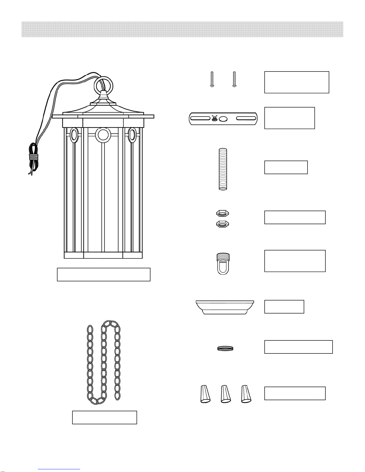
• The OUTLET BOX described in the following section is not provided. To install this
fixture, a standard OUTLET BOX needs to be pre-installed at the selected mounting
location. Power supply wires need to be run into the OUTLET BOX, extending
approximately 6” from its opening. If an OUTLET BOX does not exist, contact a
1. DISCONNECT POWER AT THE CIRCUIT BREAKER.
2
Ui
t
i
f
li
th
hi
li k
t
th
d
f
th
CHAIN
Att h
th
ASSEMBLY AND INSTALLATION:
qualified electrician to have one installed.
2
.
U
s
i
ng
t
wo pa
i
rs o
f
p
li
ers, open
th
ec
h
a
i
n
li
n
k
a
t
th
een
d
o
f
th
e
CHAIN
.
Att
ac
h
th
e
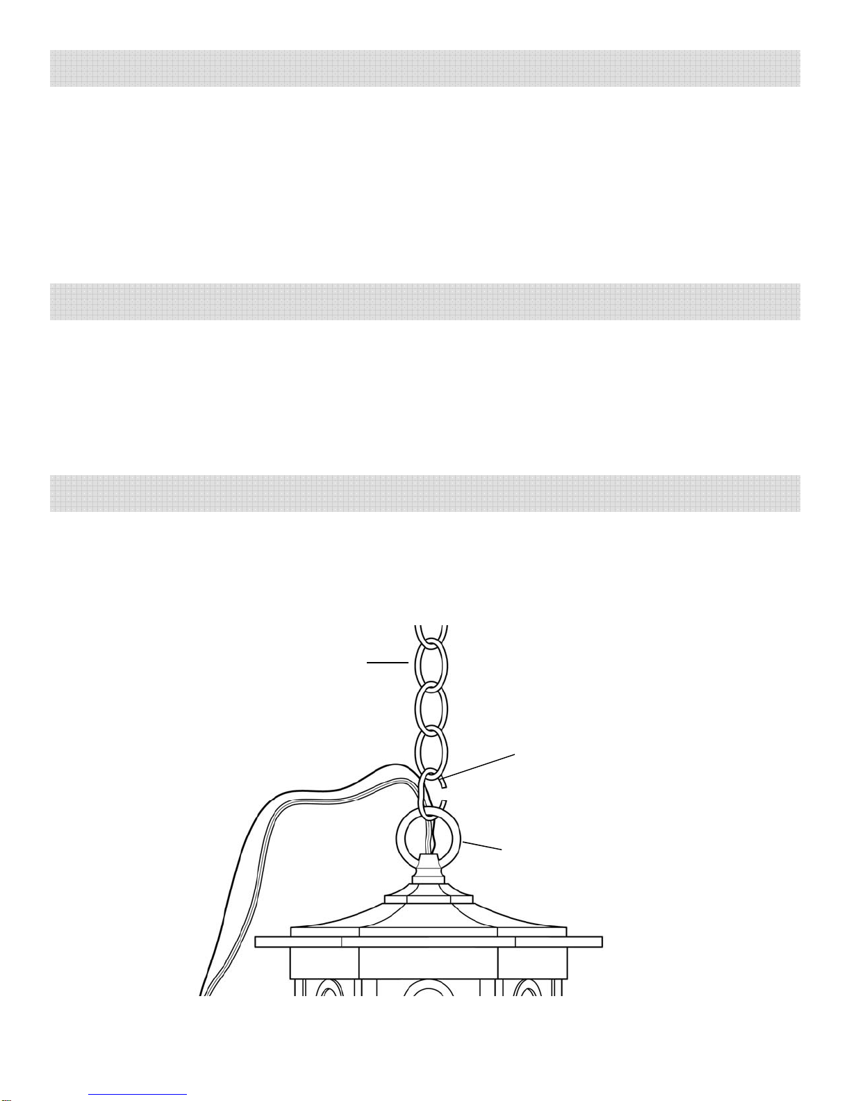
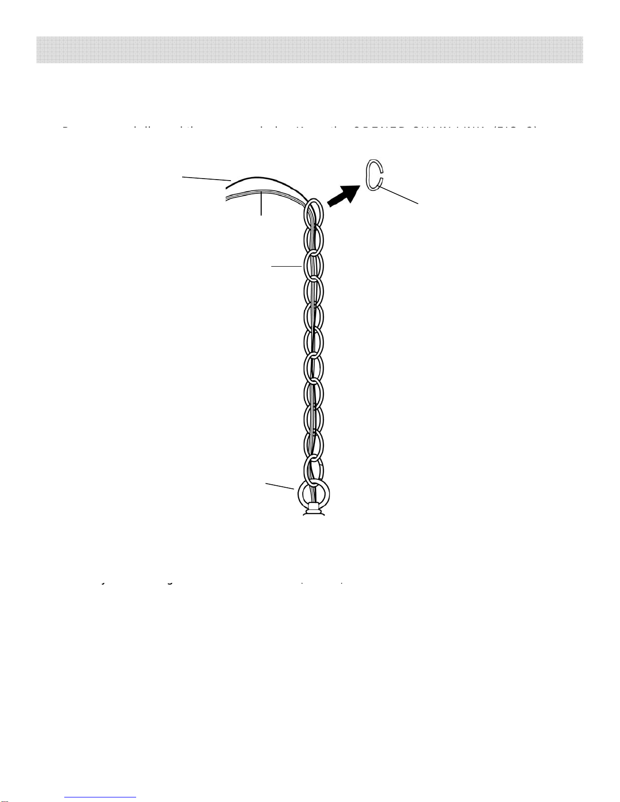
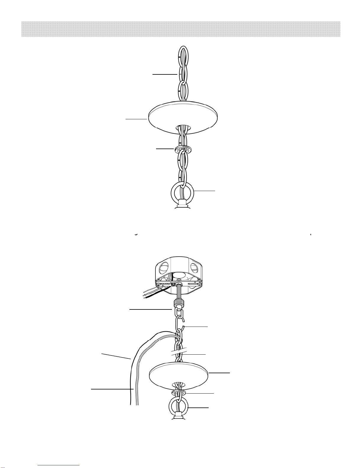
CHAIN to the TOP LOOP by hooking the OPENED CHAIN LINK to the TOP LOOP.
Using pliers, close the OPENED CHAIN LINK. (FIG. 1)
CHAIN
FIG. 1 OPENED
CHAIN
LINK
TOP
LOOP
Page 4

3. Raise the CHAIN and the MAIN FIXTURE BODY up to the OUTLET BOX to determine
the desired length needed for installation. Identify the chain link that needs to be
opened to remove the excess chain. Using two pair of pliers, open the chain link.
R
d
di d
th
hi
K
th
OPENED
CHAIN
LINK
(FIG
2
)
ASSEMBLY AND INSTALLATION (CONT.):
OPENED
R
emove an
d
di
scar
d
th
e excess c
h
a
i
n.
K
eep
th
e
OPENED
CHAIN
LINK
.
(FIG
.
2
)
FIXTURE
GROUND
WIRE
CHAIN
LINK
CORD
CHAIN
FIG. 2
TOP
LOOP
4. Thread the two HEX NUTS onto the NIPPLE to its approximate midpoint. Thread the
NIPPLE in throught the center hole of the MOUNTING BRACKET approximately 1/3 of
the wa
y
. Do not ti
g
hten the HE
X
NUTS.
(
FIG. 3
)
y
g
(
)
• Pull the SUPPLY WIRES and the SUPPLY GROUND WIRE out from the OUTLET BOX.
Attach the MOUNTING BRACKET to the OUTLET BOX by feeding the MOUNTING
SCREWS through the slots of the MOUNTING BRACKET and threading them into the
mounting holes of the OUTLET BOX. (FIG. 3)
• Thread the SCREW COLLAR LOOP 8 or 9 turns onto the bottom end of the NIPPLE.
Tighten
the
bottom
HEX
NUT
against
SCREW
COLLAR
LOOP
(FIG
3
)
Page 5
Tighten
the
bottom
HEX
NUT
against
SCREW
COLLAR
LOOP
.
(FIG
.
3
)

OUTLET
ASSEMBLY AND INSTALLATION (CONT.):
MOUNTING
BOX
MOUNTING
BRACKET MOUNTING
SCREWS
HEX NUT FIG. 3
NIPPLE
SCREW
COLLAR
LOOP
NIPPLE
7. Place the CANOPY over the OUTLET BOX and check if the midpoint of the outer
threads of the SCREW COLLAR LOOP aligns with the bottom surface of the CANOPY.
OUTLET BOX
If not, turn the SCREW COLLAR LOOP until its midpoint aligns with the CANOPY. (FIG
4)
FIG. 4
CANOPY
SCREW
COLLAR
LOOP
8
Remove
the
CANOPY
and
tighten
the
top
HEX
NUT
against
the
MOUNTING
Page 6
8
.
Remove
the
CANOPY
and
tighten
the
top
HEX
NUT
against
the
MOUNTING
BRACKET. (FIG. 3)
• Slide the THREADED RING onto the CHAIN, followed by the CANOPY. (FIG. 5)

CHAIN
ASSEMBLY AND INSTALLATION (CONT.):
CHAIN
CANOPY FIG. 5
THREADED
RING
TOP LOOP
10. Hook the previously OPENED CHAIN LINK onto the top link of the CHAIN. Raise the
OPENED CHAIN LINK alon
g
with the CHAIN and the MAIN FIXTURE BODY u
p
to the
g
p
ceiling and hook it onto the SCREW COLLAR LOOP. Using pliers, close the OPENED
CHAIN LINK. (FIG. 6)
SCREW
COLLAR
LOOP OPENED
CHAIN
LIN
K
FIG. 6
CHAIN
THREADED RING
CANOPY
CORD
FIXTURE
GROUND
WIRE
THREADED
RING
TOP LOOP
Page 7

ASSEMBLY AND INSTALLATION (CONT.):
11. Feed the CORD and FIXTURE GROUND WIRE into the CENTER HOLE of the
SCREW COLLAR LOOP, in through the NIPPLE and out to its top end, then out of the
OUTLET BOX. Continue feeding the CORD and FIXTURE GROUND WIRE, until
th
i
lk
ii
(FIG
7
&
8
)
th
ere
i
snos
l
ac
k
rema
i
n
i
ng.
(FIG
.
7
&
8
)
OUTLET
BOX
FIXTURE
GROUND
WIRE CORD
SCREW
COLLAR
LOOP FIXTURE
GROUND
CENTER
HOLE
CORD
GROUND
WIRE
FIG. 7 FIG. 8
12. Cut off an
y
excess CORD and FIXTURE GROUND WIRE
,
leavin
g
a
pp
roximatel
y
6”
y
,
g
pp y
extending from the OUTLET BOX. Split apart the CORD, separating the RIBBED
WIRE and the SMOOTH WIRE. Strip off 3/8” of insulation from each wire. Loop the
FIXTURE GROUND WIRE around the GROUND SCREW. Tighten the GROUND
SCREW against the MOUNTING BRACKET. Make the following wire connections
(FIG. 9):
WHITE (NEUTRAL) SUPPLY WIRE to RIBBED FIXTURE WIRE
BLACK (HOT) SUPPLY WIRE to SMOOTH FIXTURE WIRE
SUPPLY GROUND WIRE to FIXTURE GROUND WIRE
Wrap each wire connection with 2” of electrical tape. Carefully tuck all wire
connections
into
the
OUTLET
BOX
Page 8
connections
into
the
OUTLET
BOX
.

BLACK (HOT)
ASSEMBLY AND INSTALLATION (CONT.):
BLACK
(HOT)
SUPPLY WIRE
WIRE
SUPPLY
GROUND
WRE
RIBBED
WIRE
SMOOTH
WIRE
NUT
FIXTURE
GROUND
GROUND
SCREW
13. Slide the CANOPY up the CHAIN, toward the OUTLET BOX, up against the ceiling
surface
Slide
the
THREADED
RING
up
the
CHAIN
and
thread
it
onto
the
SCREW
WHITE
(NEUTRAL)
SUPPLY
WRE
GROUND
WRE FIG. 9
surface
.
Slide
the
THREADED
RING
up
the
CHAIN
and
thread
it
onto
the
SCREW
COLLAR LOOP to secure the CANOPY flush against the ceiling surface. (FIG. 10)
OUTLET
BOX
CANOPY THREADED
RING
SCREW
Page 9
FIG. 10
SCREW
COLLAR
LOOP

ASSEMBLY AND INSTALLATION (CONT.):
14. Install an incandescent LIGHT BULB or a Listed SBCFL (Self-Ballasted Compact
Fluorescent Lamp [not provided]) into the socketoftheMAINFIXTUREBODY. Donot
exceed a 100 Watt incandescent LIGHT BULB, or a 26 Watt SBCFL. (FIG. 11)
MAIN FIXTURE
BOCY Fig. 11
LIGHT BULB
Page 10
15. RESTORE POWER AT THE CIRCUIT BREAKER. Turn on the wall switch.

TROUBLESHOOTING:
1. Power is off. 1. Make sure power supplyis on.Lights will not turn on.
SYMPTOM POSSIBLE CAUSE CORRECTIVE ACTION
2.Faultyswitch. 2.Test or replace switch.
3.Faultywire connection. 3.Check wiring.
Fuse blows or circuit
breakertrips when lightis
turned on
1.Crossed wires or power wire is
grounding out. 1.Check wire connections.
•
To
clean
the
fixture
disconnect
power
to
the
fixture
by
turning
off
the
circuit
breaker
or
by
PRODUCT MAINTENANCE:
turned
on
.
•
To
clean
the
fixture
,
disconnect
power
to
the
fixture
by
turning
off
the
circuit
breaker
or
by
removing the fuse at the fuse box. Wait a few minutes for the fixture to cool down. Use a
dry or slightly dampened clean cloth (use clean water, never a solvent) to wipe the glass
and surface of the fixture.
• Do not use any cleaners with chemicals, solvents or harsh abrasives. If necessary, use a
mild soap to clean off any dirt or stains.
ONE YEAR LIMITED WARRANTY
Lan
gp
ort Li
g
htin
g
®
warrants this
p
roduct to be free from defects in material and
gp
gg
p
workmanship for one year from the original date of purchase by the consumer. This
warranty is limited to the counter replacement at the time of purchase, with the original
purchase receipt. Langport Lighting
®
will not be liable for the loss or damage of any
kind, incidental or consequential damages of any kind, whether based on warranty contract
or negligence, and arising in connection with the sale, use or repair of the product claimed
to
be
defective
Some
states
do
not
allow
the
exclusion
or
limitation
of
incidental
or
to
be
defective
.
Some
states
do
not
allow
the
exclusion
or
limitation
of
incidental
or
consequential damages so the above limitation may not apply to you. This warranty gives
you specific legal rights and you may also have other rights, which vary from state to state.
Misuse, accident, improper installation or maintenance will also void the warranty.
Page 11

Page 12
Table of contents