Lanpro LP-348 User manual

SpecificationsSpecifications
LP-348 USER GUIDE
LP-348
www.lanpro.com
LP348_UG_ENB02W

Table of Content
CHAPTER 1. INTRODUCTION............................................................................................................... 5
1-1OVERVIEW........................................................................................................................................5
1-2 KEY FEATURES............................................................................................................................... 6
1-3 WARNINGS....................................................................................................................................... 8
1-4 SYSTEM REQUIREMENTS............................................................................................................. 10
1-5 HARDWARE DESCRIPTION............................................................................................................ 11
1-6 HARDWARE INSTALLATION........................................................................................................... 14
CHAPTER 2. BASIC INSTALLATION AND SECURITIES ..................................................................... 18
2-1 DEFAULT FACTORY SETTINGS..................................................................................................... 18
2-2 GETTING TOKNOW RADIOWIRELESS SECURITYOPTIONS....................................................... 19
2-3 INSTALLING THE RADIO AS ANAP (ACCESS POINT) .................................................................. 20
CHAPTER 3. GENERAL INFORMATION................................................................................................ 22
3-1 INFORMATION ................................................................................................................................. 22
3-2 CONNECTION.................................................................................................................................. 24
CHAPTER 4. COPIOUS FUNCTIONALITIES ........................................................................................ 26
4-1 TIME SERVER.................................................................................................................................. 26
4-2 BRIDGE/ROUTER MODE ............................................................................................................... 27
4-3 ANYIP................................................................................................................................................ 28
4-4 UNDERSTANDINGRADIUS SETTINGS.......................................................................................... 29
4-5 HTTP REDIRECT ............................................................................................................................. 30
4-6 FIREWALLMANAGEMENT .............................................................................................................. 31
4-7 VIRTUALSERVER............................................................................................................................. 33
CHAPTER 5. WIRELESS SETUP .......................................................................................................... 35
5-1 BASIC SETTINGS............................................................................................................................. 35
5-2 VAP / VLAN SETTINGS ................................................................................................................... 37
5-3 UNDERSTANDINGWEP/WPASECURITYOPTIONS........................................................................ 39
5-4 ACCESSCONTROL.......................................................................................................................... 43
5-5 WDSMODE....................................................................................................................................... 43
5-6 SMARTWDS..................................................................................................................................... 44
5-7 ADVANCED SETTINGS.................................................................................................................... 44
CHAPTER 6. MANAGINGAND TESTINGYOURAP............................................................................... 47
6-1 SITE SURVEY .................................................................................................................................. 47
6-2 LINK TEST......................................................................................................................................... 48
CHAPTER 7. MANAGEMENT................................................................................................................. 49
7-1 CHANGE PASSWORD..................................................................................................................... 49
7-2 REMOTEMANAGEMENT.................................................................................................................. 50
7-3 UPGRADEFIRMWARE..................................................................................................................... 53
7-4 BACKUP / RESTORE SETTINGS ................................................................................................... 54
7-5 EVENT LOG...................................................................................................................................... 55
7-6 REBOOTAP....................................................................................................................................... 56
CHAPTER 8. TROUBLE SHOOTING..................................................................................................... 57
8-1 GENERALDESCRIPTIONS.............................................................................................................. 57
8-2 CONNECTION ISSUES.................................................................................................................... 59
8-3 CONFIGURATION ISSUES ............................................................................................................. 60
8-4 COMMUNICATION ISSUES............................................................................................................. 61
www.lanpro.com

Copyright
Preface
Document Conventions
This user’s manual and the software described in it are copyrighted with all rights reserved.
No part of this publication may be reproduced, transmitted, transcribed, stored in a
retrieval system, or translated into any language in any form by any means without the
written permission of Corporation.
About This Manual.
This manual explains the LP-348 enterprise-class 802.11g outdoor radio.
This publication uses the following conventions to convey instructions and
Information:
STA refers to a station
ETH refers to a PC
This symbol means reader take note. Notes contain helpful suggestions or
references to materials not contained in thismanual.
This symbol means reader be careful. In this situation, you might do something
That could result in equipment damage or loss of data.
This warning symbol means danger. You are in a situation that could cause bodily
injury. Before you work on any equipment, be aware of the hazards involved with
electrical circuitry and be familiar with standard practices for preventing accidents.
Bold: Indicates the function, important words, and so on.
www.lanpro.com

Chapter 1. Introduction
1-1 LP-348 Overview
Thank you for choosing the LP-348 Enterprise-class outdoor radio (hereafter called radio).
This radio provides a secure, affordable, and easy-to-use wireless LAN solution that
combines mobility and flexibility with the enterprise-class features required by networking
Professionals.
This chapter gives an overview of the enterprises-class radio, as well as its key features.
In addition, we detail about the hardware descriptions, system requirements and basic
Installation.
802.11a/b/g-compliant, Vlan functionality allows a single network AP to behave as “8”
number of virtual network APs. This does away with the limitation by the sheer number of
Ethernet connections that need APs acting as a proxy. WMM prioritizes traffic demands
from different applications and extends Wi-Fi’s high quality end-user experience from data
connectivity to voice, music, and video applications under a wide variety of environment.
This Access points serves as the connection point between wireless and wired networks
or as the center point of a stand-alone wireless network. In large installations, wireless
users within radio range of an access point can roam throughout a facility while
maintaining seamless, uninterrupted access to the network.
You can configure and monitor the 348 using the command-line interface (CLI), the
browser-based management system, or Simple Network Management Protocol (SNMP).
This radio currently can support data rate up to 108Mbps.
Use the instructions in this Guide to help you connect the outdoor radio, set it up, and
configure it to bridge your different networks. These instructions should be all you need to
get the most out of the radio
www.lanpro.com

1-2 Key Features
• Standards Compliant
• WEP support
• DHCP Client Support
RADIUS Accounting
• SNMP Support
• Multiple operating modes
Repeater mode
• VAPs (VLAN)
• QoS
• Wi-Fi Multi-media (WMM)
The LP-348 is user-friendly and provides solid wireless and networking support. The
following standards and conventions are supported:
The Wireless Access Point complies with the IEEE 802.11b/g for Wireless LANs.
Support for WEP is included. 64-bit, 128-bit, and 152-bit keys.
DHCP Server provides a dynamic IP address to PCs and other devices upon request. The
radio can act as a client and obtain information from your DHPC server.
Enable accounting on the access point to send accounting data about wireless client
devices to a RADIUS server on your network.
Support for Simple Network Management Protocol (SNMP) Management Information
Base (MIB) management.
1. Access point
2. StationAdapter
3. Point-to-Point Bridge.
4. Wireless Repeater
5. Inter-building
Configure the radio as a wireless repeater to extend the coverage area of your wireless
Network.
Assign Multi-SSIDs on your radio (one SSID per VAP) to differentiate policies and
services among users forming a wide variety of VLANs.
Radio also supports the voice-prioritization schemes by using the 802.11b/g wireless
phones via enable the WMM application.
•
Use this feature to support quality of service for prioritizing traffic from the Ethernet to the
access point.
•
www.lanpro.com

•Transmit Power Control
•Atheros Super G Mode
• Multiple security settings per VLAN with up to 8 VLANs
•Access Control
•Hidden Mode
Supports settable transmit power levels to adjust coverage cell size, ranging from full,
half(50%), quarter(25%) eighth(12.5%) and min.
There are several versions power versions of the LanPro 348, ranging from 0.2W, 0.5W to
1W of full output power. The 0.5W and 1W contain an aditional high performance b/g
amplifier inside the Nema4 sealed enclosure. Ask your distributor for details.
Atheros is a world lider in telecomm chipsets.
Selected by companies as IBM and Toshiba among many others.
LanPro uses Atheros to assure best performance and compatiibility with current modern
systems. Super G mode enables the transmission up to 108Mbps
Security settings for multiple groups; so employees, guests and contractors now easily
and securely share the same infrastructure.
The Access Control MAC address filtering feature can ensure that only trusted wireless
stations can use the radio to gain access to your LAN.
The SSID is not broadcast, assuring only clients configured with the correct SSID can
Connect.
www.lanpro.com

In order to comply with international radio frequency (RF) exposure limits,
dish antennas should be laced at a minimum of 8.7 inches (22 cm) from the
bodies of all persons. Other antennas should be laced a minimum of 7.9 inches
(20 cm) from the bodies of all persons.
Do not work on the system or connect or disconnect cables during periods of
lightning activity.
This equipment must be grounded. Never defeat the ground conductor or
operate the equipment in the absence of a suitably installed ground conductor.
Contact the appropriate electrical inspection authority or an electrician if you
are uncertain that suitable grounding is available.
Ultimate disposal of this product should be handled according to all national
laws and regulations.
Do not locate the antenna near overhead power lines or other electric light or
power circuits, or where it can come into contact with such circuits. When
installing the antenna, take extreme care not to come into contact with such
circuits, as they may cause serious injury or death. For proper installation and
grounding of the antenna, please refer to national and local codes (e.g.
U.S.:NFPA 70, National Electrical Code, Article 810, in Canada: Canadian
Electrical Code, Section 54).
Only trained and qualified personnel should be allowed to install, replace, or
service this equipment.
1-3 Warnings
www.lanpro.com

To meet regulatory restrictions, the LP-348 and the external antenna must be
professionally installed. The network administrator or other IT professional
responsible for installing and configuring the unit is a suitable professional
installer. Following installation, access to the unit should be password
protected by the network administrator to maintain regulatory compliance.
The Outdoor Multi-function radio and POE injector can be damaged by
incorrect power application. Read and carefully follow the installation
instructions before connecing the system to its power source.
www.lanpro.com

1-4 System Requirements
What’s In the Box?
Before installing the LP-348, make sure your system meets these requirements
• The Category 5 UTP straight through Ethernet cable with RJ-45 connector. (Between
PC and POE) . We recommend to use LanPro networking cable cat5e.
• The Category 5 SFTP straight through Ethernet cable with weather-proof RJ-45
connector. (Between POE and radio)
• A 100~240 V, 50~60 Hz AC power source
• A Web browser for configuration such as Microsoft Internet Explorer 6.0 or above, or
Netscape Navigator 4.78 or above
• At least one computer with the TCP/IP protocol installed
• 802.11 b/g Outdoor radio * 1
• Power adapter and cord * 1
• Power over Ethernet (POE) * 1
• Quick Installation Guide * 1
• Installation CD for the radio *1
• Mounting kit *1
• RJ-45 weather-proof connector for the SFTP cable * 1
If any missing or damaged, please contact your local seller.
www.lanpro.com
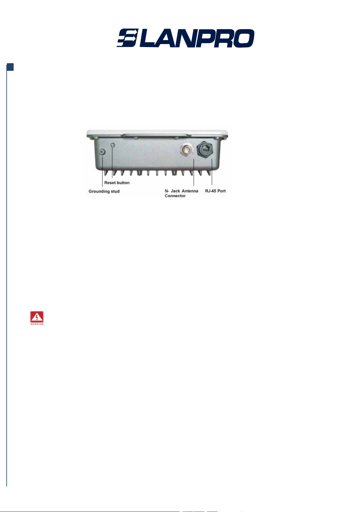
1-5 Hardware Description
MECHANICAL DESCRIPTION
Please refer to the following table for the meaning of each feature.
Please refer to the following table for the meaning of each feature.
Figure 1-1 Outdoor Multi-function Radio Figure
1 RJ-45 Port Use the SFTP cat.5 cable with weatherproof connector to connect
to the “To ODU” side of the POE injector.
2 N- Jack Antenna
Connector
3 Grounding stud Connect to the ground conductor with the ground wire.
4 Reset button Screw off this screw and insert a stick to press in and hold the reset
button for 5~10 seconds, the radio will back to factory default
Settings.
PS. The spec of the screw is “Button head socket cap screw 4*6 iso”.
Here you can attach the proper antenna with the outdoor radio to wirelessly
connect to the networks. In order to improve the RF signal radiation of your
antenna, proper antenna installation is necessary.
This equipment must be grounded. Never defeat the ground conductor or
operate the equipment in the absence of a suitably installed ground conductor.
Contact the appropriate electrical inspection authority or an electrician if you
are uncertain that suitable grounding is available.
www.lanpro.com
Other manuals for LP-348
2
Table of contents
Other Lanpro Radio manuals


