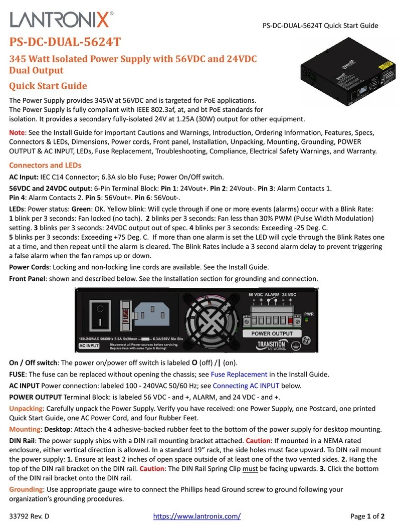
Lantronix PS-DC-DUAL-5624T User manual

PS-DC-DUAL-5624T
345 Watt Isolated Power Supply with 56VDC and
24 VDC Dual Output
Install Guide
Part Number 33788
Revision E January 2022

Lantronix PS-DC-DUAL-5624T Power Supply Install Guide
33788 Rev. E https://www.lantronix.com/ Page 2of 19
Intellectual Property
© 2022 Lantronix, Inc. All rights reserved. No part of the contents of this publication may be transmitted or reproduced in
any form or by any means without the written permission of Lantronix.
Lantronix is a registered trademark of Lantronix, Inc. in the United States and other countries. All other trademarks and
trade names are the property of their respective holders.
Patented: https://www.lantronix.com/legal/patents/; additional patents pending.
Warranty
For details on the Lantronix warranty policy, please go to our web site at
http://www.lantronix.com/support/warranty.
Contacts
Lantronix Corporate Headquarters
7535 Irvine Center Drive
Suite100
Irvine, CA 92618, USA
Toll Free: 800-526-8766
Phone: 949-453-3990
Fax: 949-453-3995
Technical Support
Phone: +1.952.358.3601 or 1.800.260.1312
Email: techsupport@transition.com
Sales Offices
For a current list of our domestic and international sales offices, go to the Lantronix web site at
www.lantronix.com/about/contact.
Disclaimer
All information contained herein is provided “AS IS.” Lantronix undertakes no obligation to update the information in this
publication. Lantronix does not make, and specifically disclaims, all warranties of any kind (express, implied or otherwise)
regarding title, non-infringement, fitness, quality, accuracy, completeness, usefulness, suitability or performance of the
information provided herein. Lantronix shall have no liability whatsoever to any user for any damages, losses and causes
of action (whether in contract or in tort or otherwise) in connection with the user’s access or usage of any of the
information or content contained herein. The information and specifications contained in this document are subject to
change without notice.
Revision History
Date
Rev
Notes
7/29/19
A
Initial release at FW Rev. 1.0.4.
8/19/19
B
Revise specs, labels and model number.
9/18/19
C
Add power cord information.
11/9/21
D
Remove PS-DC-DUAL-5612T references and update specifications.
1/26/22
E
Initial Lantronix re-brand.

Lantronix PS-DC-DUAL-5624T Power Supply Install Guide
33788 Rev. E https://www.lantronix.com/ Page 3of 19
Table of Contents
1Introduction.......................................................................................................................................................4
Ordering Information ........................................................................................................................................................... 4
Features .............................................................................................................................................................................. 4
Specifications ...................................................................................................................................................................... 5
Power Cord Specifications .................................................................................................................................................. 6
27275 AC Power Cord with locking; -NA Line Cord, Right angle.................................................................................... 6
27274 AC Power Cord with locking; -NA Line Cord ........................................................................................................ 7
3344 AC Power Cord; non-locking; -NA Line Cord ......................................................................................................... 8
Connectors and LEDs ......................................................................................................................................................... 9
Dimensions........................................................................................................................................................................ 10
Power Cords...................................................................................................................................................................... 10
Front Panel Descriptions................................................................................................................................................... 11
2Installation.......................................................................................................................................................12
Cautions and Warnings ..................................................................................................................................................... 12
Unpacking ......................................................................................................................................................................... 13
Mounting............................................................................................................................................................................ 14
Grounding.......................................................................................................................................................................... 14
Connecting POWER OUTPUT.......................................................................................................................................... 14
Connecting AC INPUT ...................................................................................................................................................... 14
PWR (Power) LED ............................................................................................................................................................ 15
Fuse Replacement ............................................................................................................................................................ 15
Installing TN 16210 Ferrite................................................................................................................................................ 15
Related Manuals ............................................................................................................................................................... 16
Application Example.......................................................................................................................................................... 16
3Related Information .........................................................................................................................................17
Troubleshooting................................................................................................................................................................. 17
Compliance Information .................................................................................................................................................... 17
Electrical Safety Warnings ................................................................................................................................................ 18
Product Label and Box Label ............................................................................................................................................ 18

Lantronix PS-DC-DUAL-5624T Power Supply Install Guide
33788 Rev. E https://www.lantronix.com/ Page 4of 19
1 Introduction
The Power Supply provides 345W at 56VDC and is targeted for PoE applications. The Power Supply is fully compliant
with IEEE 802.3af, at, and bt PoE standards for isolation. It provides a secondary fully-isolated 24V at 1.25A (30W) output
for other equipment.
Ordering Information
Model
Description
PS-DC-DUAL-5624T
Hardened 345 Watt Isolated Power Supply with 56VDC and 24VDC Dual Output
PS-DC-DUAL-5624T-
AL
Hardened 345 Watt Isolated Power Supply with 56VDC and 24VDC Dual Output with
Locked –NA Power Cord
27274
AC Power Cord with locking; -NA Line Cord
3344
AC Power Cord; non-locking; -NA Line Cord
27275
AC Power Cord with locking; -NA Line Cord, Right angle
Features
•Wide 100-240VAC input with externally accessible fuse
•56 VDC output provides plenty of margin for the powered device (PD) to meet minimum PSE output voltage
requirements:
oIEEE 802.3af (44VDC, 12V margin)
oIEEE 802.3at (50VDC, 6V margin)
oIEEE 802.3bt (52VDC, 4V margin)
•Desktop mountable / DIN rail form factor
•Full compliance with the IEEE 2250 VDC PoE isolation requirements
•Active fan speed control based on temperature (PWM)
•Front panel LED for power supply status (Normal and Alarm)
•2-Pin Alarm DC relay output monitoring five events:
oFan tachometer monitoring for low speed and lock conditions
oOver- or under-temperature
o24V output out of spec
•UL approval
•5 year warranty

Lantronix PS-DC-DUAL-5624T Power Supply Install Guide
33788 Rev. E https://www.lantronix.com/ Page 5of 19
Specifications
Output 1
Voltage 56V (terminal block)
Regulation +/- 2%
Current Rating 5.7A
Power Rating 315W
Output 2
Voltage 24V (terminal block)
Regulation +/- 5%
Current Rating 1.25A
Power Rating 30W
Input Voltage Range
100-240VAC
Input Frequency Range
47 - 63 HZ
Power Consumption
4.0A at 120VAC typical
Dimensions (HxWxD)
Width: 6.25” [159 mm] x Depth: 6.45” [164 mm] x Height: 1.75” [44 mm]
Weight
1.8 lbs. (0.72Kg)
Environment
Operating Temp.: -20°C to +70°C (restricted); -20°C to +50°C (unrestricted)
Storage Temp.: -30°C to +70°C
Operating Humidity: 5% to 95% (non-condensing)
Alarm output rating
30VDC maximum
50mA maximum
MTBF
623,377 hrs.
ENV: GB TEMP: 30.00 deg. C
TELCORDIA CALCULATION METHOD: Parts Count (Method I)
Certifications
EMI: EN55032 Class A, EN55024
Safety: EN60950, UL 60950
Warranty
Five years

Lantronix PS-DC-DUAL-5624T Power Supply Install Guide
33788 Rev. E https://www.lantronix.com/ Page 6of 19
Power Cord Specifications
Power cord specifications are provided below.
27275 AC Power Cord with locking; -NA Line Cord, Right angle
Connectors: NEMA 5-15P
IEC-60320-C13
Length: 3 ft. (0.91 m)
Gauge: 18
Jacket Type: SJTW 105⁰C
Rating: 10A – 125V
Safety: UL

Lantronix PS-DC-DUAL-5624T Power Supply Install Guide
33788 Rev. E https://www.lantronix.com/ Page 9of 19
Connectors and LEDs
AC Input
•Connector: IEC C14
•Fuse: 6.3A slo blo
•Power On/Off switch
56VDC and 24VDC output: 6-Pin Terminal Block
•Pin 1: 24Vout+
•Pin 2: 24Vout-
•Pin 3: Alarm Contacts 1
•Pin 4: Alarm Contacts 2
•Pin 5: 56Vout+
•Pin 6: 56Vout-
LEDs
•Power status
oGreen: OK
oYellow blink: Will cycle through if one or more events (alarms) occur with one of these Blink Rates:
1 blink per 3 seconds: Fan locked (no tach)
2 blinks per 3 seconds: Fan less than 30% PWM (Pulse Width Modulation) setting
3 blinks per 3 seconds: 24VDC output out of spec
4 blinks per 3 seconds: Exceeding -25 Deg. C
5 blinks per 3 seconds: Exceeding +75 Deg. C
If more than one alarm is set the LED will cycle through the Blink Rates one at a time, and then repeat until the alarm is
cleared.
Note: These Blink Rates include a 3 second alarm delay to prevent triggering a false alarm when the fan ramps up or
down.

Lantronix PS-DC-DUAL-5624T Power Supply Install Guide
33788 Rev. E https://www.lantronix.com/ Page 11 of 19
Front Panel Descriptions
The Power Supply front panel is shown and described below. See the Installation section for the actual grounding and
connection procedures.
PS-DC-DUAL-5624T Hardened 345 Watt Isolated Power Supply with 56VDC and 24VDC Dual Output
On / Off switch: The power on/power off switch is labeled O (off) /|(on).
FUSE: The fuse can be replaced without opening the chassis; see Fuse Replacement below.
AC INPUT Power connection: labeled 100-240VAC 50/60 Hz; see Connecting AC INPUT below.
POWER OUTPUT Terminal Block: labeled 56 VDC - and +, ALARM, and 24 VDC - and +. See Connecting POWER
OUTPUT below.
PWR (Power) Status LED: a bi-color green/amber LED; Green = OK, Yellow blink = Fault Event Detected (see LED Blink
Rate above).

Lantronix PS-DC-DUAL-5624T Power Supply Install Guide
33788 Rev. E https://www.lantronix.com/ Page 12 of 19
2 Installation
Cautions and Warnings
Cautions and Warnings appear here and may appear throughout this manual where appropriate. Failure to read and
understand the information identified by this symbol could result in poor equipment performance, damage to the
equipment, or injury to persons.
Cautions indicate that there is the possibility of poor equipment performance or potential damage to the equipment.
Warnings indicate that there is the possibility of injury to person.
See Electrical Safety Warnings on page 16 for Electrical Safety Warnings translated into multiple languages.
High Risk Activities Disclaimer: Components, units, or third-party products used in the product described herein are
NOT fault-tolerant and are NOT designed, manufactured, or intended for use as on-line control equipment in the following
hazardous environments requiring fail-safe controls: the operation of Nuclear Facilities, Aircraft Navigation or Aircraft
Communication Systems, Air Traffic Control, Life Support, or Weapons Systems ("High Risk Activities").
Lantronix and its supplier(s) specifically disclaim any expressed or implied warranty of fitness for such High Risk Activities.
Notice: Not Designed for Use in Life Support Equipment or Applications: These products are not designed for use in life
support equipment or applications that would cause a life-threatening situation if any such product failed. Do not use this
product in these types of equipment or applications.
Operating Temperature - RESTRICTED ACCESS LOCATION: A location for equipment where both of the following
paragraphs apply:
– access can only be gained by SERVICE PERSONS or by USERS who have been instructed about the reasons
for the restriction applied to the location and about any precautions that shall be taken; and
– access is through the use of a TOOL or lock and key, or other means of security, and is controlled by the authority
responsible for the location.
NOTE: The requirements for equipment intended for installation in RESTRICTED ACCESS LOCATIONS are the same as
for OPERATOR ACCESS AREAS, except as given in 1.7.17, 2.1.3 and 4.5.1.
1.2.7.4 TOOL: A screwdriver or any other object which may be used to operate a screw, latch or similar fixing means.
1.2.7.5 BODY: All accessible conducive parts, shafts of handles, knobs, grips and the like, and metal foil in contact with
all accessible surfaces of insulating material.
1.2.7.6 SAFETY INTERLOCK: A means either of preventing access to a hazardous area until the hazard is removed, or
of automatically removing the hazardous condition when access is gained.
WARNING
HOT SURFACE
DO NOT
TOUCH

Lantronix PS-DC-DUAL-5624T Power Supply Install Guide
33788 Rev. E https://www.lantronix.com/ Page 13 of 19
Input Power:
100-240 VAC ~ (Operating Temperature -20 to +50°C Unrestricted)
100-240 VAC ~ (Operating Temperature -20 to +70°C Restricted)
50/60 Hz 5.5A max
Output Power:
Power 1: 56VDC @ 315 Watts, 5.6 Amps
Power 2: 24VDC @ 30 Watts, 1.25 Amps
Unpacking
Carefully unpack the Power Supply. Verify you have received the items below.
Save the packaging for possible future use.
•One Power Supply
•One Postcard
•One printed Quick Start Guide, 33792
•One AC Power Cord (option)
•Four Rubber Feet
•One Snap-on Ferrite, TN 16210

Lantronix PS-DC-DUAL-5624T Power Supply Install Guide
33788 Rev. E https://www.lantronix.com/ Page 14 of 19
Mounting
Desktop: You can attach the four adhesive-backed rubber feet to the bottom of the power supply for desktop mounting.
DIN Rail: The power supply ships with a rack DIN rail bracket attached. Caution: If mounted in a NEMA rated enclosure,
either vertical direction is allowed. In a standard 19” rack, the side holes must face upward. To attach the power supply to
a DIN rail:
1. General caution for Thermals: Make sure there is at least 2 inches of open space outside of at least one of the two
vented sides. See below.
2. Hang the top of the DIN rail bracket on the DIN rail. Caution: The DIN Rail Spring Clip must be facing upwards, as
shown below.
3. Click the bottom of the DIN rail bracket onto the DIN rail.
Grounding
Connecting POWER OUTPUT
Use 14 AWG stranded or better wire (typ.) to connect to 56 VDC@315W.
Use 20 AWG stranded or better wire (typ.) to connect to 24 VDC@30W.
Refer to the powered device documentation for specific connection information; see the Related Manuals section below.
Connecting AC INPUT
Connect the male end of the provided AC power cord to the power supply AC input first, and then connect the other end to
a live 3-prong outlet.

Lantronix PS-DC-DUAL-5624T Power Supply Install Guide
33788 Rev. E https://www.lantronix.com/ Page 15 of 19
PWR (Power) LED
When the bi-color green/yellow PWR LED is lit Green, the power being supplied is OK.
If the bi-color green/yellow LED is blinking yellow, a fan, voltage, or temperature event is occurring.
Fuse Replacement
The AC INPUT is 100-240VAC 50/60Hz 5.5A. The Fuse is a 5x20mm 6.3A/250V SB (slo blo) externally-accessible fuse.
Warning: Disconnect all Power sources before servicing.
Caution: Replace fuse with same Type & Rating!
Installing TN 16210 Ferrite
For EMC reasons, install Snap-on Ferrite, TN 16210, over the 24 VDC (PS-DC-DUAL-5624T) output wires after
installation.
1. Open Ferrite.
2. Place the Ferrite over the 24 VDC Outputs.
3. Snap Ferrite in place.

Lantronix PS-DC-DUAL-5624T Power Supply Install Guide
33788 Rev. E https://www.lantronix.com/ Page 16 of 19
Related Manuals
•PS-DC-DUAL-5624T Power Supply Quick Start Guide, 33792
•Quick Start Guide - SISPM1040-384-LRT-C and SISPM1040-362-LRT, 33726
•Install Guide - SISPM1040-384-LRT-C and SISPM1040-362-LRT, 33727
•Web User Guide - SISPM1040-384-LRT-C and SISPM1040-362-LRT, 33728
•CLI Reference - SISPM1040-384-LRT-C and SISPM1040-362-LRT, 33729
Application Example
The example below shows a SISPM1040-384-LRT-C switch, Enclosure Door sensor, and PS-DC-DUAL-5624T power
supply in a single cabinet/enclosure. Warning: Ensure that the target alarm input is capable of accepting the applied
voltage (24VDC).
To configure Digital I/O in the SISPM1040-384-LRT-C via the Web UI:
1. Click Configuration > System > Digital I/O.
2. Specify the DI Normal Mode.
3. Enter the desired Normal and Abnormal alarm text to display in Syslog.
4. Click the Apply button.

Lantronix PS-DC-DUAL-5624T Power Supply Install Guide
33788 Rev. E https://www.lantronix.com/ Page 17 of 19
3 Related Information
Troubleshooting
1. Check the PWR LED for status; see the PWR (Power) LED description on page 15.
2. Check the LED for On or alarm event blinking:
a. A short or overload of the 56V will be indicated by no power LED or possibly a quick On/Off cycling.
b. A short or overload of the 24V output will be indicated by “24VDC output out of spec” blink rate.
3. Verify the AC power source is good (a live 3-prong outlet).
4. Make sure the fuse is not blown; replace if necessary.
5. Contact Technical Support; see Contact Us on page 11.
Compliance Information
Declaration of Conformity
Manufacture’s Name: Transition Networks, Inc.
Manufacture’s Address: 10900 Red Circle Drive, Minnetonka, Minnesota 55343 U.S.A.
Declares that the products:
PS-DC-DUAL-5624T Standalone Power Supply
Conforms to the following Product Regulations:
FCC Part 15 Class A, EN 55032:2012, EN 55024:2010
Directive 2014/30/EU
Low-Voltage Directive 2014/35/EU
IEC /EN 60950-1:2006+A2:2013
2011/65/EU EN 50581:2012
UL 60950-1
With the technical construction on file at the above address, this product carries the CE Mark
I, the undersigned, hereby declare that the equipment specified above conforms to the above Directive(s) and
Standards(s).
Place: Minnetonka, Minnesota
Date: July 29,2019
Signature: Stephen Anderson
Full Name: Stephen Anderson
Position: Vice President of Engineering
FCC Regulations
NOTE: This equipment has been tested and found to comply with the limits for a Class A digital device, pursuant to part
15 of the FCC Rules. These limits are designed to provide reasonable protection against harmful interference when the
equipment is operated in a commercial environment. This equipment generates, uses, and can radiate radio frequency
energy and, if not installed and used in accordance with the instruction manual, may cause harmful interference to radio
communications. Operation of this equipment in a residential area is likely to cause harmful interference in which case
the user will be required to correct the interference at his own expense.
This device complies with part 15 of the FCC Rules. Operation is subject to the following two conditions: (1) This device
may not cause harmful interference, and (2) this device must accept any interference received, including interference
that may cause undesired operation.

Lantronix PS-DC-DUAL-5624T Power Supply Install Guide
33788 Rev. E https://www.lantronix.com/ Page 18 of 19
Electrical Safety Warnings
Electrical Safety
IMPORTANT: This equipment must be installed in accordance with safety precautions.
Elektrische Sicherheit
WICHTIG: Für die Installation dieses Gerätes ist die Einhaltung von Sicherheitsvorkehrungen erforderlich.
Elektrisk sikkerhed
VIGTIGT: Dette udstyr skal installeres i overensstemmelse med sikkerhedsadvarslerne.
Elektrische veiligheid
BELANGRIJK: Dit apparaat moet in overeenstemming met de veiligheidsvoorschriften worden geïnstalleerd.
Sécurité électrique
IMPORTANT: Cet équipement doit être utilisé conformément aux instructions de sécurité.
Sähköturvallisuus
TÄRKEÄÄ: Tämä laite on asennettava turvaohjeiden mukaisesti.
Sicurezza elettrica
IMPORTANTE: questa apparecchiatura deve essere installata rispettando le norme di sicurezza.
Elektrisk sikkerhet
VIKTIG: Dette utstyret skal installeres i samsvar med sikkerhetsregler.
Segurança eléctrica
IMPORTANTE: Este equipamento tem que ser instalado segundo as medidas de precaução de segurança.
Seguridad eléctrica
IMPORTANTE: La instalación de este equipo deberá llevarse a cabo cumpliendo con las precauciones de seguridad.
Elsäkerhet
OBS! Alla nödvändiga försiktighetsåtgärder måste vidtas när denna utrustning används.
Product Label and Box Label
You can find device information on the product label and box label.

Lantronix PS-DC-DUAL-5624T Power Supply Install Guide
33788 Rev. E https://www.lantronix.com/ Page 19 of 19
Lantronix Corporate Headquarters
7535 Irvine Center Drive
Suite100
Irvine, CA 92618, USA
Toll Free: 800-526-8766
Phone: 949-453-3990
Fax: 949-453-3995
Technical Support
+1.952.358.3601, 1.800.260.1312, or techsupport@transition.com
Sales Offices
For a current list of our domestic and international sales offices, go to the Lantronix web site at
www.lantronix.com/about/contact.
Other manuals for PS-DC-DUAL-5624T
1
This manual suits for next models
1
Table of contents
Other Lantronix Power Supply manuals