Montageanleitung
Assembly instruction
Gültig ab/
valid from
03.05.2019
EPIC®H-DD 24 - 216 EINSÄTZE
EPIC
®
H-DD 24 - 216 Insulation bodys
Dokument/
document
: L11285000DE_EN
Version/
version
: 00
Seite 1 von 4
page 1 of 4
Wir behalten uns alle Rechte gemäß DIN ISO 16016 vor. We reserve all rights according to DIN ISO 16016.
Artikelbeschreibung
Article designation
Kontakt Typ
Connection type
Anzahl Arbeitskontakte
Number of operating contacts
EPIC® H-DD24 SCM STECKEREINSATZ gedreht/
machined
EPIC® H-DD24 BCM STECKDOSENEINSATZ gedreht/
machined
EPIC® H-DD42 SCM STECKEREINSATZ gedreht
/ machined
EPIC® H-DD42 BCM STECKDOSENEINSATZ gedreht
/ machined
EPIC® H-DD72 SCM STECKEREINSATZ gedreht
/ machined
EPIC® H-DD72 BCM STECKDOSENEINSATZ gedreht
/ machined
EPIC® H-DD108 SCM STECKEREINSATZ gedreht
/ machined
EPIC® H-DD108 BCM STECKDOSENEINSATZ gedreht
/ machined
EPIC® H-DD144 SCM STECKEREINSATZ gedreht
/ machined
EPIC® H-DD144 BCM STECKDOSENEINSATZ gedreht
/ machined
EPIC® H-DD216 SCM STECKEREINSATZ gedreht
/ machined
EPIC® H-DD216 BCM STECKDOSENEINSATZ gedreht
/ machined
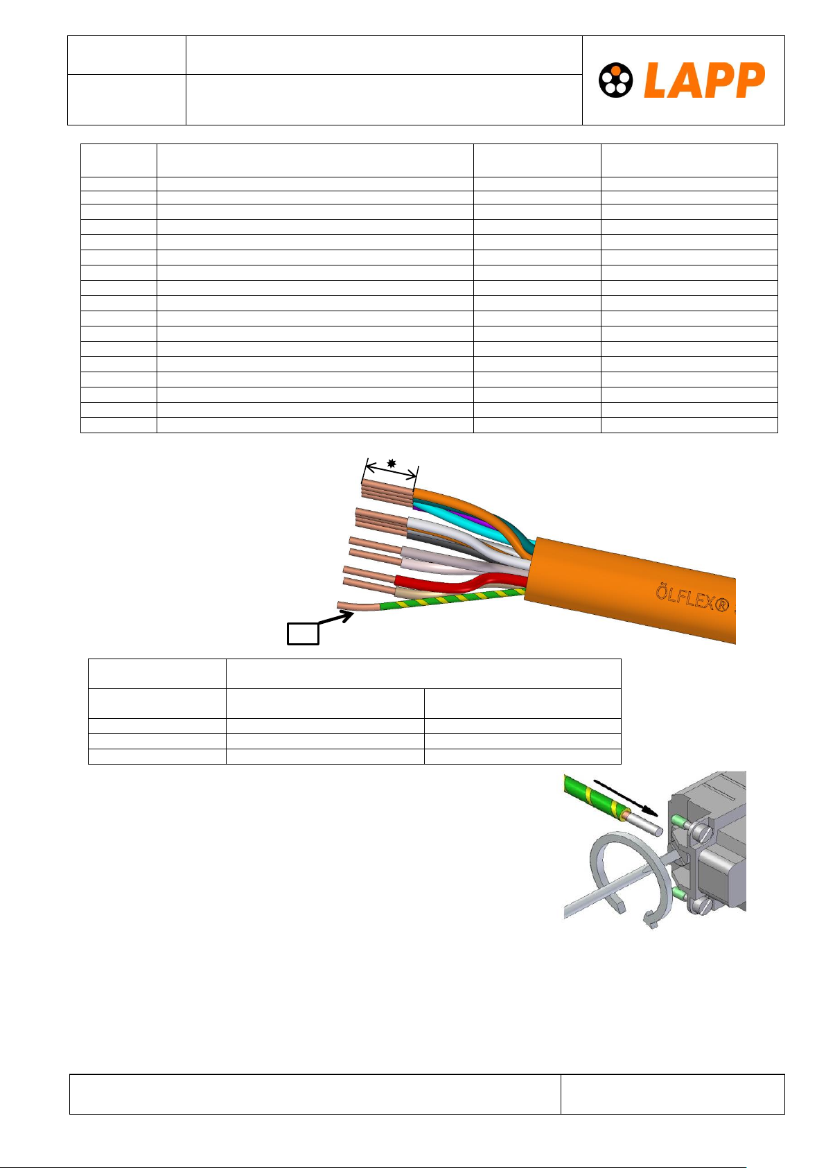
1Abmanteln
Dismantle
2 Abisolieren
Strip
Querschnitte
Cross section
Abisolierlänge
Stripping length
Für gestanzte Arbeitskontakte
For stamped live contacts
Für gedrehte Arbeitskontakte
For machined live contacts
PE-Leiter: An den PE-Leiter muss eine Aderendhülse oder ein Kabelschuh
angeschlossen werden. Die Abisolierlänge ist davon abhängig und muss
vom Anwender ermittelt werden.
Anschließend mit der PE-Klemme befestigen. Anzugsmoment: 1,2 Nm
PE conductor: A ferrule or cable lug must be connected to the PE conductor.
The stripping length depends on this and must be determined by the user.
After that connect it to the PE-terminal. Tightening torque: 1,2 Nm


