Larius MIRO LINER Operating manual

Line striper
with diaphragm pump
PAINT SPRAYING EQUIPMENT
www.larius.com
Ediz. 002 - 11/2012
MIRÓ LINER
OPERATING AND MAINTENANCE INSTRUCTION
ENGLISH

manufacturing in Italy since 1969
Larius S.r.l, founded in 1969, designs and ma-
nufactures painting equipment, and transfer and
extrusion pumps.
Larius S.r.l is a company with a great industrial
tradition and an innovative technological culture.
Internal production, based on innovation and re-
search, is flexible to industry changes in order to
achieve the primary objective of creating value.
Larius S.r.l is the only leading Italian company in
the international market. The brand is distributed
worldwide, through an extensive network of distri-
butors and resellers, and is a guarantee of Total
Product Quality in the industrial, plastics, construc-
tion, wood and road marking sectors.
INVEST IN LARIUS
INVEST IN PRODUCTIVITY
Once again
a step ahead...
Each day we strive further
to satisfy your work
requirements
PAINT SPRAYING EQUIPMENT
www.larius.com

PROFESSIONAL LINE STRIPERS
The best solution for your time and job
AIRLESS LINE QUALITY
High-pressure spraying is the fastest and most productive line painting method
- High-quality line painting throughout the application with sharp and even lines
- The paint dries quickly and one pass is enough for a well-defined line
- Perfect lines on the most different surfaces
- 30% higher productivity and 20% overspray reduction
TESTED TECHNICAL QUALITY
LARIUS line stripers combine product performance with operator requirements
- High-quality raw materials assure resistance, functionality and 100% reliability
- Easy and safe machine starting and control
- Reduced wear, original spare parts, technical service
DEMONSTRATED OPERATIONAL QUALITY
LARIUS line stripers provide operational efficiency that increase the result of the appli-
cation
- Operational flexibility: suitable for indoor and outdoor applications
- Fast operations control: easy controls centralised in front of the operator
- Quick colour change: (paint preparation not required)
- Easy use and service while in operation (the gun can be demounted without tools) -
Comfortable handling and light vehicle
- Multi-purposes: can be also used as a normal spraying equipment
MATERIALS
Almost all road marking paints are 100% compatible with water-based products. The
LARIUS Airless Line Painters must be used with filtered paint specific for airless appli-
cations.
AIRLESS LINE STRIPERS APPLICATIONS
- Parking lots (schools, hotels, airports, supermarkets, factories, train stations, ports....)
- Outdooor public areas;
- Industrial and exhibition building areas;
- Freeway service areas and service stations;
- Mid-road marking, pedestrian crossings, road junctions
- Marking of indoor and outdoor logistic areas
- Sports and play grounds
www.larius.com

LINER 3000
Medium line marking and road maintenance jobs.
DALI’ LINER SELF-PROPELLED
Medium line marking and road maintenance jobs
EXCALIBUR LINER
Medium line marking and road maintenance jobs
PROFESSIONAL
www.larius.com

DRAGON LINER SELF-PROPELLED
Big line marking and road maintenance jobs
EVEREST TH SELF-PROPELLED
Big line marking and road maintenance jobs
VIKING LINER SELF-PROPELLED
Big line marking and road maintenance jobs
K2 ECO LINER
Medium line marking and road maintenance jobs.
LINE STRIPERS
www.larius.com

Due to a constant product improvement programme, the factory reserves the right
to modify technical details mentioned in this manual without prior notice.
This manual is to be considered as an English language translation of the
original manual in Italian. The manufacturer shall bear no responsibility for any
damages or inconveniences that may arise due to the incorrect translation of the
instructions contained within the original manual in Italian.

Ed. 002 - 11/2012
LINE MARKING WITH DIAPHRAGM PUMP
INTRODUCTION .................................................. p.1
WARNINGS .......................................................... p.2
WORKING PRINCIPLE ........................................ p.3
TECHNICAL DATA ................................................ p.5
DESCRIPTION OF THE EQUIPMENT ................. p.7
TRANSPORT AND UNPACKING ......................... p.10
SAFETY RULES ................................................... p.10
Conditions of guarantee ....................................... p.10
SETTING-UP ........................................................ p.11
Flexible recirculation tube connection .............. p.11
Pump unit flexible tube connection .................. p.11
Starting the motor ............................................ p.12
Washing of the new equipment ........................ p.13
Preparation of the paint .................................... p.14
REGULATIONS .................................................... p.15
Adjusting the gun position ................................ p.15
OPERATION ......................................................... p.16
Setup procedure............................................... p.16
Adjusting pump unit speed ............................... p.16
Spray adjustment ............................................. p.16
CLEANING AT THE END OF THE WORK ........... p.17
GENERAL MAINTENANCE ..................................... p.18
Daily ......................................................................... p.18
Periodically ............................................................... p.18
ROUTINE MAINTENANCE ...................................... p.18
Control oil level in the motor
............................. p.18
Top up hydraulic oil
........................................... p.18
Release the suction valve
................................. p.18
Cleaning the compression valve
....................... p.19
Replacing hydraulci oil
...................................... p.20
TROUBLESHOOTING ......................................... p.21
CORRECT PROCEDURE OF
DECOMPRESSION .............................................. p.22
SPARE PARTS
COMPLETE PETROL ENGINE
CASING REF..4809 .............................................. p.24
HYDRUALIC BODY .............................................. p.26
COMPLETE COLOR BODY REF. 21625 ............. p.28
FILTER GROUP REF. 16200 ................................ p.29
COMPLETE 25 L TANK REF.4810 ....................... p.31
COMPLETE 50 L TANK RIF.4895 ......................... p.30
COMPLETE FRAME REF. 4874 WITH
STEERING UNIT REF. 4876 ................................ p.32
HIGH PRESSURE SPRAY GUN AT 250 .............. p.33
ACCESSORIES .................................................... p.35
WE ADVISE THE USE OF THIS EQUIPMENT ONLY BY PROFESSIONAL OPERATORS.
ONLY USE THIS MACHINE FOR USAGE SPECIFICALLY MENTIONED IN THIS MANUAL.
Thank you for choosing a LARIUS S.R.L. product.
As well as the product purchased,
you will receive a range of support services
enabling you to achieve the results desired,
quickly and professionally.
www.larius.com
MIRÓ LINER
1
A
B
C
D
E
F
G
H
M
N
O
P
Q
R
S
T
I
J
K
L
U

Ed. 002 - 11/2012
Read this operator’s manual carefully before using the equipment.
An improper use of this machine can cause injuries to people or things.
Do not use this machine when under the influence of drugs or alcohol.
Do not modify the equipment under any circumstances.
Use products and solvents that are compatible with the various parts of the equipment, and read the manufacturer’s warnings carefully.
See the Technical Details for the equipment given in the Manual.
Check the equipment for worn parts once a day. If any worn parts are found, replace them using ONLY original spare parts.
Keep children and animals away from work area.
Comply with all safety standards.
It indicates an accident risk or serious damage to equipment if this warning is not followed.
It indicates important recommendations about disposal and recycling process of products in accordance with the environmental regulations.
WARNINGS The table below provides the meaning of the symbols used in this manual in relation to using, earthing,
operating, maintaining, and repairing of this equipment.
It indicates a fire or explosion risk if this warning is not followed.
Eliminate all ignition sources such as pilot lights, cigarettes, portable electric lamps and plastic drop cloths.
Keep work area free of debris.
ONLY use this equipment in a well ventilated area.
EARTH ALL THE EQUIPMENT LOCATED IN THE WORK AREA.
Do not form connections or switch light switches on or off if the air contains inflammable fumes.
If electrical shocks or discharges are encountered the operation being carried out using the equipment must be stopped immediately.
Keep a fire extinguisher at hand in the immediate vicinity of the work area.
It indicates wound and finger squashing risk due to movable parts in the equipment.
Tenersi lontano dalle parti in movimento.
Do not use the equipment without the proper protection.
Before any inspection or maintenance of the equipment, carry out the decompression procedure explained in this manual, and prevent
any risk of the equipment starting unexpectedly.
Report any risk of chemical reaction or explosion if this warning has not been given.
There is a risk of injury or serious lesion related to contact with the jet from the spray gun. If this should occur, IMMEDIATELY contact
a doctor, indicating the type of product injected.
Do not spray before the guard has been placed over the nozzle and the trigger on the spray gun.
Do not put your fingers in the spray gun nozzle.
Once work has been completed, before carrying out any maintenance, complete the decompression procedure explained in this manual.
Report any danger of electric shock if the warning and presence of live electrical parts has not been indicated.
Store in a dry place and do not expose to the rain.
Check that the cables are in good condition.
Switch off the equipment and discharge any electricity before cleaning or maintaining the equipment.
Mark any clamps attached to earth cables.
Use ONLY 3-wire extension cords and grounded electrical outlets.
Before starting work make sure that the electrical system is earthed and that it complies with safety standards.
It is obligatory to wear suitable clothing as gloves, goggles and face shield.
Wear clothing that complies with the safety standards in force in the country in which the equipment is used.
Do not wear bracelets, earrings, rings, chains, or anything else that may hinder the operator’s work.
Do not wear clothing with wide sleeves, scarves, ties, or any other piece of clothing that could get tangled up in moving parts of the
equipment during the work, inspection, or maintenance cycles.
www.larius.com
MIRÓ LINER
2

Ed. 002 - 11/2012
A
WORKING PRINCIPLE
MIRÓ LINER unit is defined line striper with diaphragm pump
An electric diaphragm pump is used for high pressure paint spraying
without air (known as “airless”).
This unit is powered by a petrol engine. An eccentric mounted on
the motor shaft drivers a piston which conveys oil to a diaphragm
on every stroke. The moving diaphragm draws the paint in through
the intake valve, compresses it and drives it out through the tiny
hole in the spray gun nozzle. An hydraulic valve on the hydraulic
case head allows setting and checking the pressure of the paint
product at the pump outlet. A second hydraulic safety valve to avoid
over-pressure, ensures total equipment reliability.
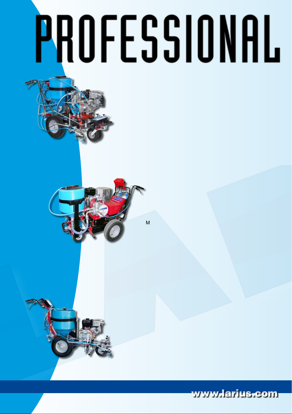
MIRÓ LINER is a small professional line striper that, thanks to
its reliable characteristics, grants a high quality performance when
used during marking and maintenance of urban roads. Being
an airless machine, the paint is atomised without air, therefore
without overspray, providing sharp high quality lines, with even
paint thickness. Thanks to the possibility of a quick colour change,
it allows a 30% increase of the production rate.
The equipment can be supplied, upon request, complete with a
glass beads dispenser.
The control zone offers the possibility of:
• Activating the spraying gun;
• Enabling or disabling the frontal steering wheel;
• Adjusting the operating pressure.
This type of equipment is capable of painting one line at a time
in a single color.
The line can be either solid or dotted, according to working re-
quirements.
1 2
MIRÓ LINER is ideal for small marking and maintenance jobs.
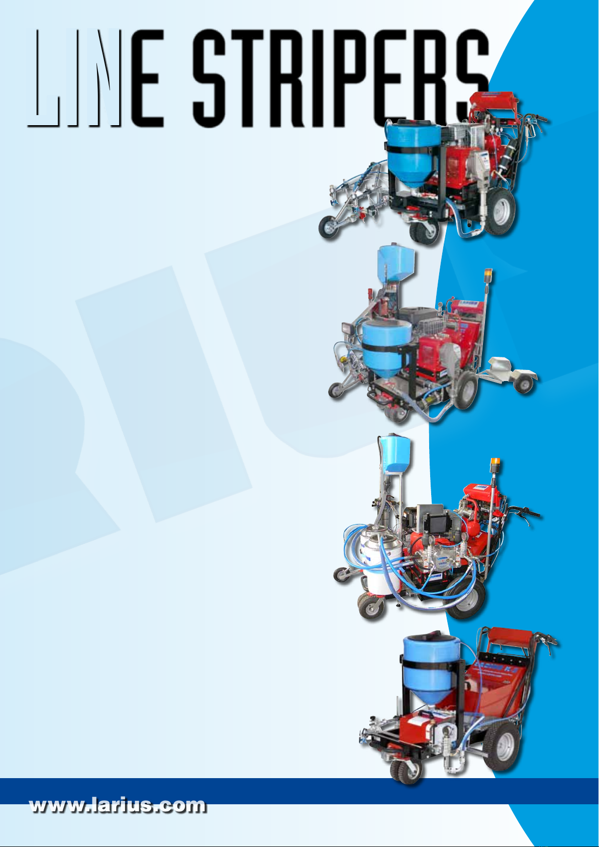
MIRÓ LINER allows for the marking and maintaining of all types
lines on highways, freeways, pedestrian crossings, parking lots
and squares, as well as every horizontal marking required by the
highway code.
Airless marking has numerous proven benefits with respect to
line-markers with pressurised tanks, which have been rendered
obsolete by airless-technology line markers.
Airless line-marking guarantees:
• Decreased Environmental Impact;
• Decreased drying time.
The paint dries quickly and the line is defined in a uniform manner
with a single coat. The airless function requires the use of filtered
paint which is specifically designed for airless application. This
means that the paint is homogeneous, of a smooth and uniform
consistency and will not form crusts, nor will it become gelatinous
or thick. With this airless line-marker, the paint adheres firmly to
all types of pavement, with optimal visibility, and is resistance to
wear caused both by traffic as well as atmospheric agents.
SOLID LINE BROKEN LINE
Use water or non-refractive solvent filtered paint
specifically designed for airless application.
This line-marker utilises non-premixed paints. This allows it to
achieve about 30 % more yield with respect to standard line-
markers. Every model is also an airless spray gun which can be
used in the construction/decoration sector together with washable
products, enamels, breathable paints and flooring resins.
A vast assortment of accessories is available to satisfy every
customer demand.
In the MIRÓ LINER model, the paint canister can be loaded di-
rectly upon the undercarriage or else poured into the non-stick, 50
L tank. In every case, cleaning, maintenance and colour change
operations are facilitated.
The line-marker is equipped with pivoting frontal wheel which even
increases the agility of the larger models.
www.larius.com
MIRÓ LINER
3

Ed. 002 - 11/2012
20L tank
50L tank
www.larius.com
MIRÓ LINER
4

B
C
A
Ed. 002 - 11/2012
B
TECHNICAL DATA
MIRÓ LINER
5 kW
2,2 l/min
210 bar
AT 250
11x40 - 13x40 - 15x40
50l - 20l
1
series
Small jobs of line marking and road maintenance
series
105 kg
(A) 160 cm
(B) 110 cm
(C) 90 cm
Internal combustion engine power
Max. Delivery
Max. pressure
Airless spray-gun
Size of nozzles
Tank
Colors
Manual line-marking
Applications
Multi-use sprayer
Weight
Lenght
Height
Width
www.larius.com
MIRÓ LINER
5

Ed. 002 - 11/2012
Standard equipment Accessories
Rif. 4502
manual gun beads
dispenser
Rif. 4038
Laser pointer kit
Rif.4506
Working spotlight
Nozzle height
from ground
10 cm
15 cm
20 cm
25 cm
30 cm
35 cm
~ 3 cm
~ 6 cm
~ 10 cm
20-degree angle
Line Width
~ 5 cm
~ 7 cm
~ 8 cm
~ 10 cm
~ 12 cm
40-degree angle
Line Width
60-degree angle
Line Width
~ 10 cm
~ 13 cm
~ 16 cm
~ 20 cm
~ 23 cm
~ 26 cm
N°1 Filter with pressure gauge
N°1 High pressure tube 3/16”, 10 m
N°1 Recirculation tube
N°1 50 L gravity tank + closing valve and
extactable filter
N°1 Manual airless spray-gun AT250
N°1 Super fast clean base
N°1 Super fast clean nozzle 11-40
N°1 Super fast clean nozzle 13-40
N°1 Super fast clean nozzle 15-40
N°1 Tool pack
APPLICATION FIELDS
• External or underground parking lots (schools, hotels, airports,
supermarkets, train stations, subway stations, ports);
• Outodoor public areas;
• Industrial and exhibition building zones;
• Freeway service areas and service stations;
• Pedestrian median lines, intersections, bicycle tracks, reserved
lanes;
• Marking of indoor and outdoor logistic areas
• Sports and play grounds.
NOZZLES POSITION TABLE
www.larius.com
MIRÓ LINER
6

8
1
65
2
5
2
3
8
9
1
3
4
9
4
7
7
Ed. 002 - 11/2012
CDESCRIPTION OF THE EQUIPMENT
POS.
1
2
3
4
5
6
7
8
9
Product filter
Pressure valve
Hydraulic oil filling cap
Pumping unit
Oil level liht
Oil discharging cap
Oil filter
Suction valve
Pressure gauge
DESCRIPTION DESCRIPTION
POS.
www.larius.com
MIRÓ LINER
7

10 11 12
12
11
6
13
19 18 14
14
18
17 15
16
16
17
15
13
Ed. 002 - 11/2012
10
11
12
13
14
15
16
17
18
19
lt. 50 tank
Gun operating lever
Directional wheel lock/release lever
Fuel tank
Accelerator
Start-up cord
Cold start-up lever
Fuel tap
Air filter
Pivoting wheel
POS.
DESCRIPTION DESCRIPTION
POS.
www.larius.com
MIRÓ LINER
8

20
19
26
20
21
23
26
22
23
20
22
21
24
25
Ed. 002 - 11/2012
20
21
22
23
24
25
26
Recirculation tube
Product feeding tube
Color unit
Recirculation valve
AT 250 gun
Spraying gun feeding tube
Brake
POS.
DESCRIPTION DESCRIPTION
POS.
www.larius.com
MIRÓ LINER
9

Ed. 002 - 11/2012
D
E
TRANSPORT
AND UNPACKING
•
The packed parts should be handled as indicated in the
symbols and markings on the outside of the packing
.
•
Before installing the equipment, ensure that the area to
be used is large enough for such purposes, is properly
lit and has a clean, smooth floor surface
.
•
The manufacturer will not be responsible for the un-
loading operations and transport to the workplace of
the machine
.
•
Check the packing is undamaged on receipt of the
equipment. Unpack the machine and verify if there
has been any damage due to transportation
.
In case of damage, call immediately LARIUS and the
Shipping Agent. All the notices about possible damage
or anomalies must arrive timely within 8 days at least
from the date of receipt of the plant through Registered
Letter to the Shipping Agent and to LARIUS
.
The user is responsible for the operations of unloading
and handling and should use the maximum care so as
not to damage the individual parts or injure anyone.
To perform the unloading operation, use only qualified
and trained personnel (truck and crane operators, etc.)
and also suitable hoisting equipment for the weight of
the installation or its parts.
Follow carefully all the safety rules.
The personnel must be equipped with the necessary
safety clothing.
The disposal of packaging materials is a customer’s
competence and must be performed in accordance
with the regulations in force in the country where the
plant is installed and used.
It is nevertheless sound practice to recycle packaging
materials in an environment-friendly manner as much
as possible
.
SAFETY RULES
• THE EMPLOYER SHALL TRAIN ITS EMPLOYEES ABOUT
ALL THOSE RISKS STEMMING FROM ACCIDENTS, ABOUT
THE USE OF SAFETY DEVICES FOR THEIR OWN SAFETY
AND ABOUT THE GENERAL RULES FOR ACCIDENT
PREVENTION IN COMPLIANCE WITH INTERNATIONAL
REGULATIONS AND WITH THE LAWS OF THE COUNTRY
WHERE THE PLANT IS USED.
• THE BEHAVIOUR OF THE EMPLOYEES SHALL STRICTLY
COMPLY WITH THE ACCIDENT PREVENTION AND ALSO
ENVIRONMENTAL REGULATIONS IN FORCE IN THE
COUNTRY WHERE THE PLANT IS INSTALLED AND USED.
Read carefully and entirely the following instruc-
tions before using the product. Please save these
instructions in a safe place.
The unauthorised tampering/replacement of one
or more parts composing the machine, the use of
accessories, tools, expendable materials other than
those recommended by the manufacturer can be
a danger of accident.
The manufacturer will be relieved from tort and
criminal liability.
• KEEP YOUR WORK PLACE CLEAN AND TIDY. DISORDER
WHERE YOU ARE WORKING CREATES A POTENTIAL RISK
OF ACCIDENTS.
• ALWAYS KEEP PROPER BALANCE AVOIDING UNUSUAL
STANCE.
• BEFORE USING THE TOOL, ENSURE THERE ARE NOT
DAMAGED PARTS AND THE MACHINE CAN WORK PRO-
PERLY.
• ALWAYS FOLLOW THE INSTRUCTIONS ABOUT SAFETY
AND THE REGULATIONS IN FORCE.
• KEEP THOSE WHO ARE NOT RESPONSIBLE FOR THE
EQUIPMENT OUT OF THE WORK AREA.
• NEVER EXCEED THE MAXIMUM WORKING PRESSURE
INDICATED.
• NEVER POINT THE SPRAY GUN AT YOURSELVES OR
AT OTHER PEOPLE. THE CONTACT WITH THE CASTING
CAN CAUSE SERIOUS INJURIES. IN CASE OF INJURIES
CAUSED BY THE GUN CASTING, SEEK IMMEDIATE MEDI-
CAL ADVICE SPECIFYING THE TYPE OF THE PRODUCT
INJECTED. NEVER UNDERVALUE A WOUND CAUSED BY
THE INJECTION OF A FLUID.
• ALWAYS DISCONNECT THE SUPPLY AND RELEASE THE
PRESSURE IN THE CIRCUIT BEFORE PERFORMING
ANY CHECK OR PART REPLACEMENT OF THE EQUIP-
MENT.
• NEVER MODIFY ANY PART IN THE EQUIPMENT. CHECK
REGULARLY THE COMPONENTS OF THE SYSTEM. RE-
PLACE THE PARTS DAMAGED OR WORN.
• TIGHTEN AND CHECK ALL THE FITTINGS FOR CONNEC-
TION BETWEEN PUMP, FLEXIBLE HOSE AND SPRAY GUN
BEFORE USING THE EQUIPMENT.
• ALWAYS USE THE FLEXIBLE HOSE SUPPLIED WITH STAN-
DARD KIT. THE USE OF ANY ACCESSORIES OR TOOLING
OTHER THAN THOSE RECOMMENDED IN THIS MANUAL,
MAY CAUSE DAMAGE OR INJURE THE OPERATOR.
• THE FLUID CONTAINED IN THE FLEXIBLE HOSE CAN
BE VERY DANGEROUS. HANDLE THE FLEXIBLE HOSE
CAREFULLY. DO NOT PULL THE FLEXIBLE HOSE TO
MOVE THE EQUIPMENT. NEVER USE A DAMAGED OR A
REPAIRED FLEXIBLE HOSE.
www.larius.com
MIRÓ LINER
10

F1
F2
F3
F4
Ed. 002 - 11/2012
F
• NEVER SPRAY OVER FLAMMABLE PRODUCTS OR SOL-
VENTS IN CLOSED PLACES.
• NEVER USE THE EQUIPMENT IN POTENTIALLY EXPLO-
SIVE ENVIRONMENTS.
The high speed of the product in the hose can create
static electricity through discharges and sparks.
It is suggested to earth the equipment.
The pump is earthed through the earth cable of
the supply. The gun is earthed through the high
pressure flexible hose.
All the conductors near the work area must be
earthed.
Always check the product is compatible with the
materials composing the equipment (pump, spray
gun, flexible hose and accessories) with which it
can come into contact. Never use paints or sol-
vents containing halogen hydrocarbons (as the
methylene chloride).
If these products come into contact with aluminium
parts can provoke dangerous chemical reactions
with risk of corrosion and explosion.
IF THE PRODUCT TO BE USED IS TOXIC, AVOID
INHALATION AND CONTACT BY USING PRO-
TECTION GLOVES, GOGGLES AND PROPER
FACE SHIELDS.
TAKE PROPER SAFETY MEASURES FOR THE
PROTECTION OF HEARING IN CASE OF WORK
NEAR THE PLANT.
The conditions of guarantee do not apply in the
following situations:
- improper washing and cleaning of components
causing malfunction, wear or damage to the
equipment or any of its parts;
- improper use of the equipment;
- use that does not conform with applicable national
legislation;
- incorrect or faulty installation;
- modifications, interventions and maintenance that
have not been authorised by the manufacturer;
- use of non-original spare parts or parts that do
not correspond to the specific model;
- total or partial non-compliance with the instruc-
tions provided.
CONDITIONS OF GUARANTEE
SETTING-UP
TUBE CONNECTIONS
Flexible re-circulation tube connection
• Connect the flexible re-circulation tube
(F1)
to the connector
(F2)
ensuring to tighten the fittings (the use of two wrenches
is suggested)
.
Pump unit flexible tube connection
• Connect the product suction flexible tube
(F3)
to the connector
(F4)
ensuring to tighten the fittings (the use of two wrenches
is suggested)
.
www.larius.com
MIRÓ LINER
11

FUEL
F6
F5
F7
F10
F9
F11
1/2
F8
Ed. 002 - 11/2012
• Open the fuel tap (F8) and position it to “ON” (I).
• Turn the equipment’s switch (F10) to ON (I)
• Bring the accelerator lever (F11) to about 1/2 of its run.
• Pull lever (F9) for first start-up (only when cold).
• It is recommended to use the hose provided with the standard
kit.
NEVER use a damaged or a repaired flexible hose.
NEVER use sealants on fittings’ threads
.
Flexible tube and spray gun connection
• Connect the flexible tube
(F5)
to the connector
(F6)
ensuring
to tighten the fittings (the use of two wrenches is suggested)
.
STARTING THE MOTOR
In order to start the motor, proceed as follows:
• Fill the fuel tank
(F7)
.
www.larius.com
MIRÓ LINER
12

F13
F14
F12
F12
F15
F17
Ed. 002 - 11/2012
• Pull the lever (F12) for the first cold start up).
WASHING OF THE NEW EQUIPMENT
• The equipment has already been adjusted at our factory with
light mineral oil left inside the pumping group as protection.
Therefore, wash with diluent before sucking the product.
• Fill the product tank with wash fluid.
• Clean the inside of the tank with a brush.
• Open the product output tap (F14).
• Ensure the gun (F13) is without nozzle.
• Open the recirculating-safety valve (F15).
www.larius.com
MIRÓ LINER
13

F17
F13
F18
F15
Ed. 002 - 11/2012
• Start the motor following the indications provided in the
chapter “STARTING THE MOTOR”.
•
Visually check that the wash fluid starts to re-circulate within
the tank
(F17).
• Rotate the pressure setting knob (F16) slightly clockwise so
that the machine operates at minimum power.
• Once the wash fluid has circulating enough, close the
recirculating-safety valve (F15).
• When the pump idles stop the combustion engine.
• At this point the machine is ready. If water-based paints are
to be used, after the wash with solvent wash the tank again
with soap and water, then rinse with clean water (repeating
the previously described procedures).
• Insert the manual gun trigger lock and assemble the nozzle.
•
Remove the gun
(F13)
from its support and point it into a
container
(F18).
Hold the trigger down (to perform the cle-
aning) until clean solvent comes out, or else until all of the
wash fluid has been expelled from the tank.
Repeat the same operations with clean solvent if
necessary.
• After having completed the wash operations, bring the han-
dle to its MIN position (F17) and point the gun (F13) into a
collection container (F18) and press the trigger to release
the residual pressure. Release the trigger when finished.
NEVER spray solvents indoors. In addition, it is
recommended to keep away from the pump in
order to avoid the contact between the solvent
fumes and the motor.
• Mix and filter the product before using it. For filtration
use CLOSE-MESH (rif. 214) and LARGE-MESH (rif. 215)
LARIUS METEX braids.
PRODUCT PREPARATION
MAKE SURE THE PRODUCT IS SUITABLE TO BE
USED WITH A SPRAY GUN.
www.larius.com
MIRÓ LINER
14
F16
Table of contents
Other Larius Construction Equipment manuals
Popular Construction Equipment manuals by other brands

Kato Imer
Kato Imer CARRY 107 operating instructions

Komatsu
Komatsu WD600-3 Operation & maintenance manual

GSi
GSi C Series Assembly instructions

HIAB
HIAB 160TM Operating manual / spare parts list

Worldwide Construction And Forestry Division
Worldwide Construction And Forestry Division 450J Repair manual

GEISMAR
GEISMAR TH 70 STP Instructions for use and maintenance