Larson Electronics, LLC Phone: (800) 369-6671 Fax: (903) 498-3364 www.larsonelectronics.com
4of 4
EYS INSTALLATION / SEALING COMPOUND
HAZARD WARNINGS: May cause irritation to eyes and skin. Inhalation dust is considered a nuisance
dust. Avoid physical contact by wearing appropriate gloves and dust goggles. If powder gets into eyes,
flood immediately for 15 minutes with water. Wash hand thoroughly with soap and water after
handling
Mix 2 parts Sealing Compound to 1 part clean
water. Mix thoroughly. Do not mix more than
can be used in 15 minutes. Use cold water as
warm water accelerates set.
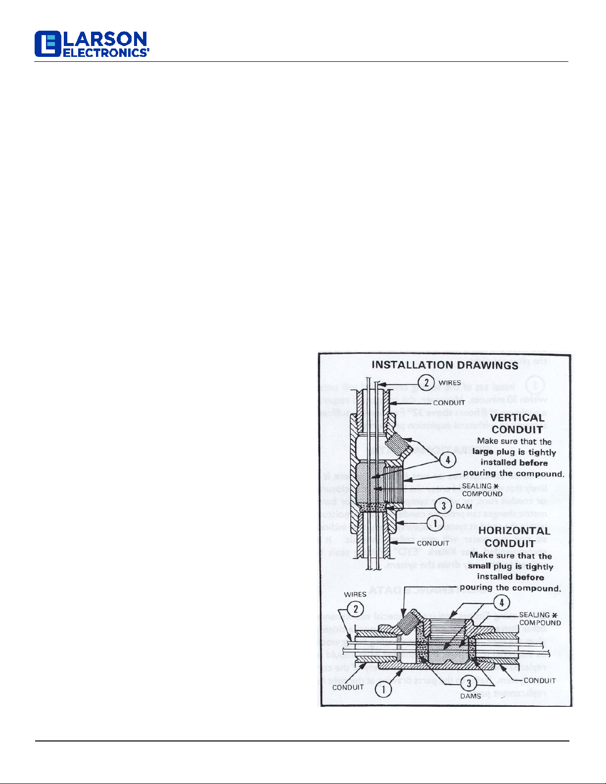
Vertical Installation:
Seal fitting is installed with the small access plug in the
up position. Both access plugs are removed after
conductors are installed. Damming fiber is installed
through the lower access port into the lower portion of
the fitting body. Care must be taken to insure the fiber
fills all voids around each conductor, as well as between
conductors and the wall of the seal fitting body. Replace
the lower (large) access plug. Mix compound according
to manufacturer instructions and pour through the upper
(smaller) access port until compound reaches the base
of the access port threads. Replace remaining plug in
upper access port. Both plugs are to be made up with
five threads engaged and wrench tight.
Horizontal Installation:
Seal body is installed with both access plugs in the up
position. Both access plugs are removed after
conductors are installed. Damming fiber is installed
through the large access port into both ends of the seal
fitting body to allow sealing compound to flow to the
required thickness (Table A). Care must be taken to
insure the fiber fills all voids around each conductor, as
well as between conductors and the wall of the seal
body.
Replace the small access port plug. Mix compound
according to manufacturer instructions and pour through
the large access port until compound reaches the base
of the access port threads. Replace large plug. Both
plugs are to be made up with five threads engaged and
wrench tight.
Class I Group A & B Installations:
Vertical Installation:
Sealing compound is to be mixed at ambient
temperature above 40°f. / 4°c. and poured into fitting
with body temperature not below 40°f. / 4°c. Ambient
temperature (of fitting) must not drop below 40°f. / 4°c.
for 72 hours. Compound must cure for 72 hours before
circuits are placed into service.
Horizontal Installation:
Sealing compound is to be mixed at room temperature,
and poured into fitting at room temperature. Ambient
temperature of fitting must remain at room temperature
for 72 hours. Compound must cure for 72 hours before
circuits are placed into service.
Class I Group C & D Installations:
Sealing compound is to be mixed at ambient
temperature above 35°f. / 2°c. and poured into fitting
with body temperature not below 35°f. / 2°c. Ambient
temperature (of fitting) must not drop below 35°f. / 2°c.
for 8 hours. Compound must cure for 8 hours before
circuits are placed into service.