3
Instruction Manual
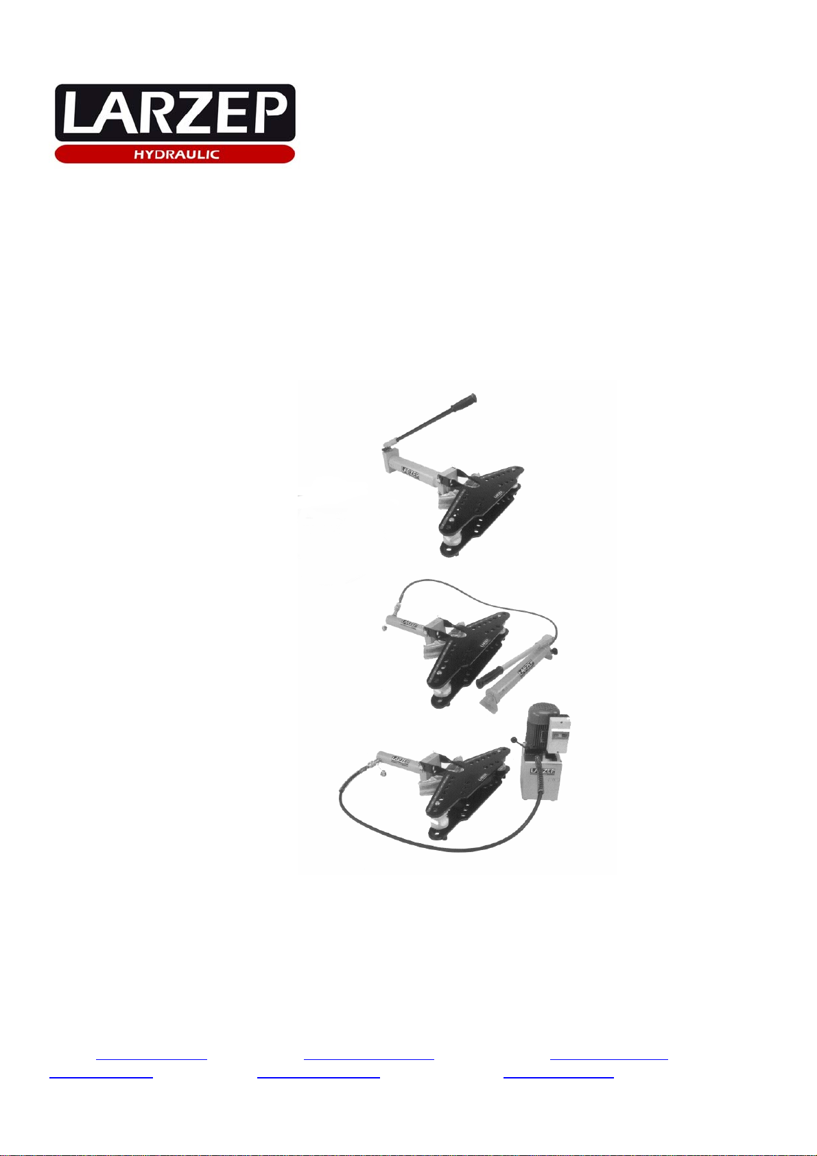
Hydraulic Bender
“VA1225” “VC1225” “VA1227” “VB1227”
MODEL VA1225 VC1225 VA1227 VB1227
DESCRIPTION Bender with cylinder and manual
pump Bender with cylinder and electro
pump Bender with horizontal
bottle jack Bender with horizontal
bottle jack and tripod.
CYLINDER SM01025 single acting and spring
return SM01025 single acting and spring
return - -
JACK - - AV1227 Horizontal
Bottle jack with internal
spring return
AV1227 Horizontal
Bottle jack with internal
spring return
PUSH CAPACITY 11.1 ton 11.1 ton 11.1 ton 11.1 ton
PISTON STROKE 262 mm 262 mm 285 mm 285 mm
PUMP W00607 YAM1114 - -
TANK CAPACITY 660 cc 2 Litres - -
FLOW PER STROKE 2.6 cc 0.35 L/min. 4.2 cc 4.2 cc
POWER - .37 Kw380 V 50Hz 3 ph - -
WEIGHT 55 Kg 50 Kg 61 Kg 70 Kg
3. START UP.
The bender is packed in a sturdy wooden box, which protects it from the knock damage throughout the transportation. Once the tool is used, clean it and
keep it into the box, to be stored until next usage.
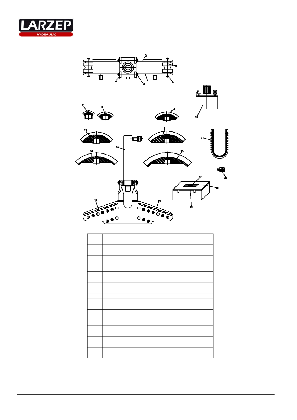
Unpack the equipment assuring that all the parts indicated in the drawing provided in the manual are found and the material has not been damaged.
The hydraulic part is provided threaded to the structure plate of the grounds. Mount in this plate the lower and upper grounds. (Stick with the tube
measures up faced) with the axles and clips. Checking that the upper ground tilts free.
In model VB1227, assemble the tripod by screwing the coupling into the support plate and inserting it into the tripod shaft.
MODEL VA1225 MODEL VC1225 MODEL VA1227 MODEL VB1227
1. Connect the pump to the cylinder
via the hose and the quick plug. 1. Connect the electric pump to the
cylinder via the hose and the quick plug. 1. This model does not require
any type of hydraulic connection. 1. This model does not require any type
of hydraulic connection.
2. Enable a few pump strokes using
the lever with the screw slightly
loose (turn anticlockwise) in order to
bleed the circuit.
2. Replace the electric pump’s transport
plug with its operating plug. 2. Enable a few pump strokes
using the lever with the screw
slightly loose (turn anticlockwise)
in order to bleed the circuit.
2. Enable a few pump strokes using the
lever with the screw slightly loose (turn
anticlockwise) in order to bleed the
circuit.
3. Tighten the screw manually (turn
clockwise). 3. Make sure that the voltage in the mains
corresponds to that required by the
machine and that the motor rotates in the
direction indicated by the arrow.
3. Tighten the screw manually
(turn clockwise). 3. Tighten the screw manually (turn
clockwise).
4. When you pump now, the cylinder
piston will move forward. 4. With the manual distributor control set
to tank (lever towards the motor), press
the switch in order to start the motor.
4. When you pump now, the jack
piston will move forward. 4. When you pump now, the jack piston
will move forward.
5. When the screw is loosened once
again, the piston moves back due to
the action of an internal spring.
5. Alter making sure that the working
zone is unoccupied and all the elements
are fixed in place moves the distributor
lever to its open position by turning 90º.
The cylinder piston will move forward.
5. When the screw is loosened
once again, the piston moves back
due to the action of an internal
spring.
5. When the screw is loosened once
again, the piston moves back due to the
action of an internal spring.
6. When the lever is moved back to its
tank position, the piston will move back
due to the pressure applied by the cylinder
spring.
BENDING OPERATION
Once you know the dimensions of the pipe you need to bend, proceed as follows:
1. Lift the upper template so that it is vertical. (1)
2. Place the shafts in the corresponding holes in accordance with the pipe dimensions, as indicated on the chart.
3. Place the shafts rollers in the position corresponding to the pipe to be bent. See the makings on the rollers.
4. Place the bender corresponding to the pipe on the protruding end of the piston.
5. Close the upper template, thereby fixing all elements in place.
6. Insert the pipe to be bent in one side, between the two templates. Be careful not to rotate the rollers out of their correct position and make sure that the
bender stays on the end of the piston. (2)
7. Activate the hydraulic element as described in the previous section.
8. Move the piston out as far as necessary in order to achieve the desired curve angle, bearing in mind the elasticity of the pipe at all times. (3)
9. Depressurise the hydraulic element, the piston will move back in releasing the pipe.
10. Lift the template and remove the pipe. The bender will normally remain attached to the pipe. Use a plastic mallet to separate them. (4)