Issue 1
Page 10 of 24
EL-SMS-2G-TP / TP+ / PROBE-G USER MANUAL
Thermistor Probe
These units are supplied with a thermistor probe to sense temperature. The
EL-SMS-2G-TP is supplied by default with a Type 2 (Standard) thermistor probe.
The ELSMS2GTP+ is supplied by default with a Type A (High Accuracy) probe
and the EL-SMS-2G-PROBE-G with a Type A probe inserted into a glycol bottle.
The thermistor probes connect to the unit via the 3.5mm jack socket.
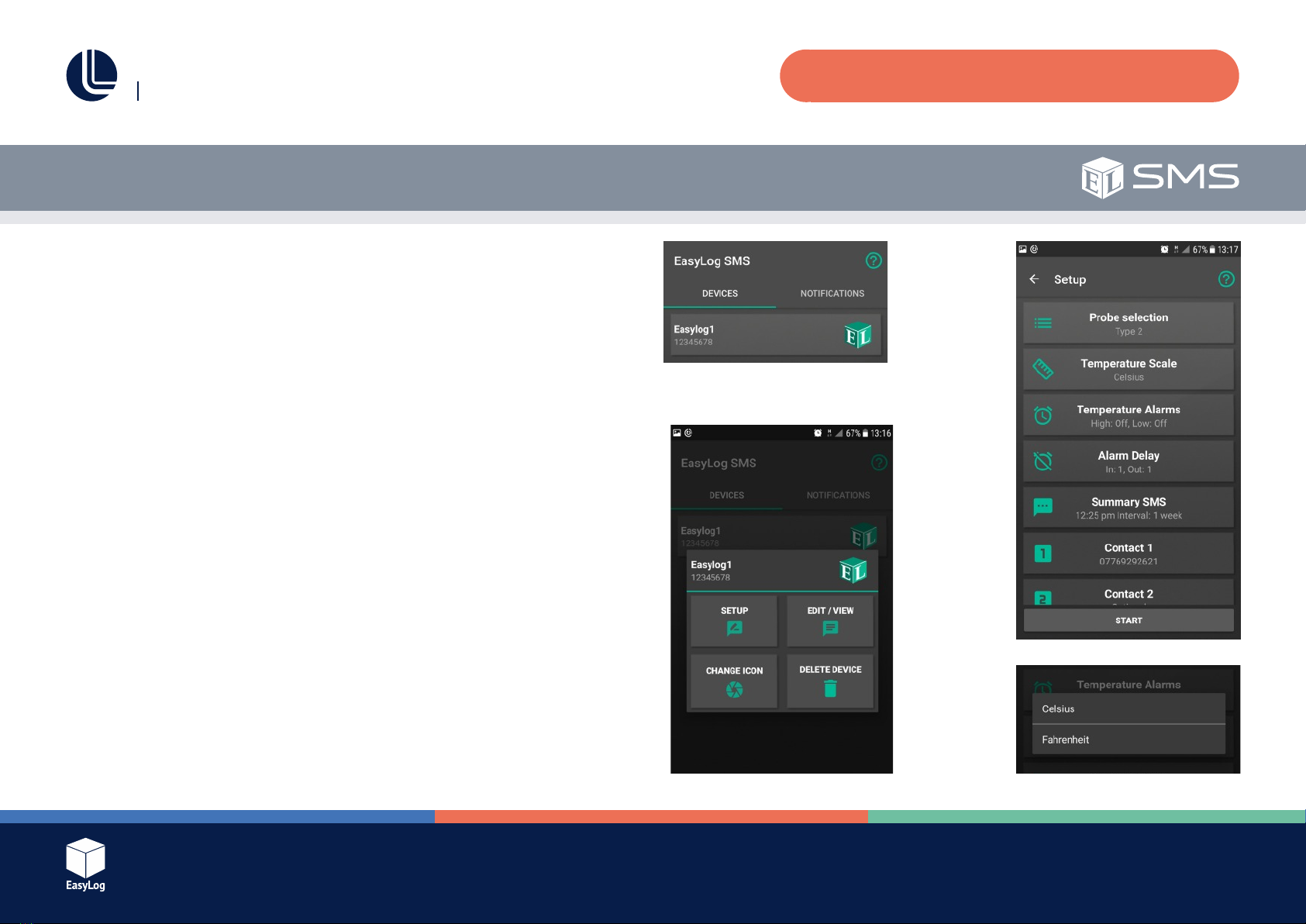
Thethermistorprobetypecanbeselectedwhentheunitisconfiguredusing
the App.
Temperature Monitoring Interval
These units will take a temperature reading every minute. For this reason it may
take up to one minute before the unit responds to a change in temperature.
Multiple SMS Destinations
Theunitscansendnotificationstoamaximumofthreemobilephonenumbers.
It should be noted that operating any unit with more than one destination mobile
phonenumberwillsignificantlyreducetheexpectedbatterylifeandmayincur
additional costs as more messages are sent.
When multiple destination numbers are used these units will attempt to send
notificationmessagestoeachphonenumber.Iftheunitisabletosuccessfully
transfer the SMS to the mobile network for at least one of the destination numbers
then it will assume that the delivery of the message was successful. Be aware
however that actual delivery of the message is reliant on the mobile network and
mobile operator’s services operating normally.
User Guide
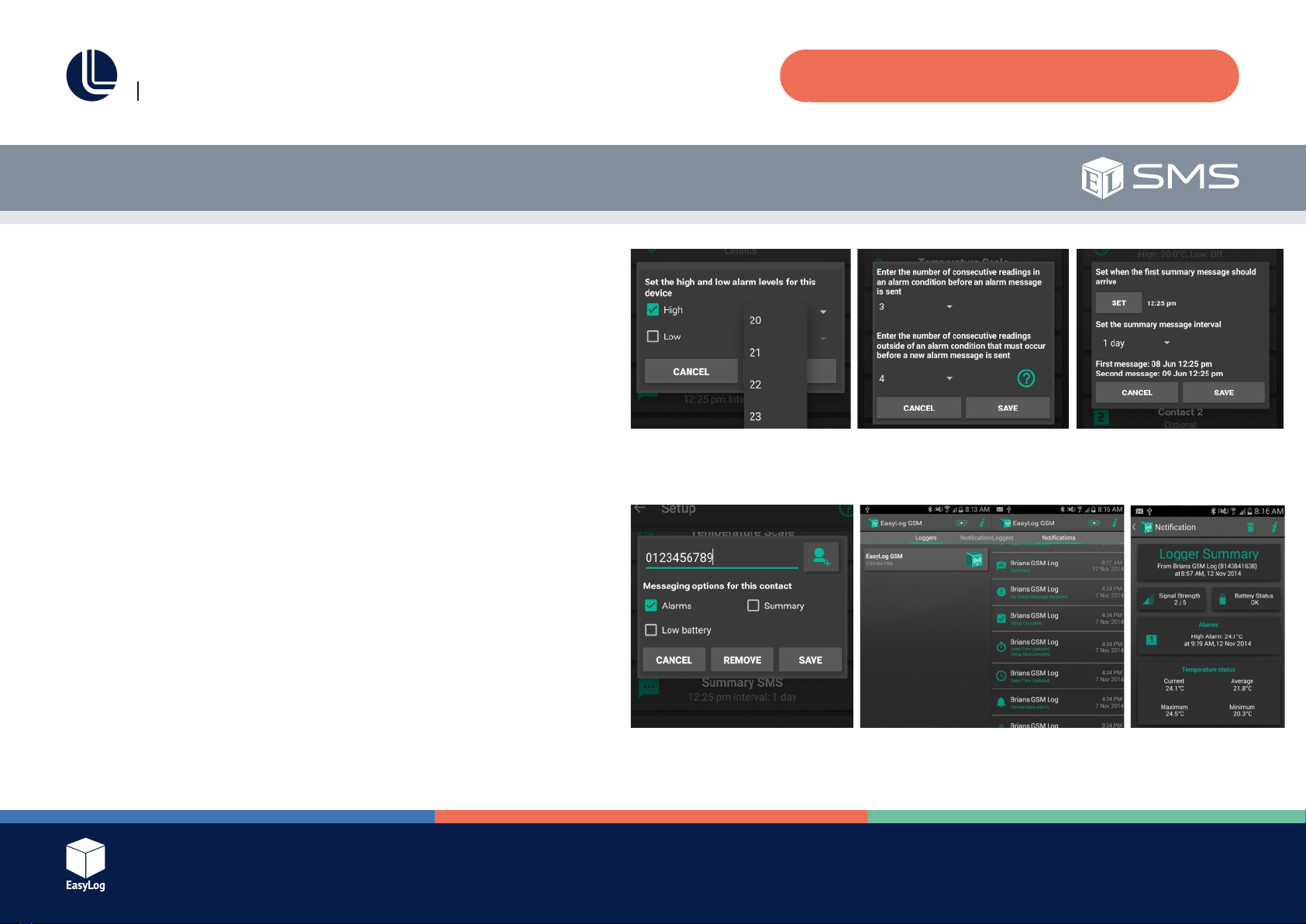
Alarm Delay Operation
These units allow a separate pre and post alarm delay to be applied to any set
temperature alarms. This is useful to prevent sending excessive text messages if
themeasuredtemperatureisfluctuatingaroundeitherthehighorlowalarmlevels.
When a knockin delay is used, these units will wait until that number of consecutive
temperature readings have all been in an alarm condition before sending a
temperature alert message. If a knockout delay is used, they will stay in an alarm
stateuntilthespecifiednumberofconsecutivereadingsarealloutsideofanalarm
condition. When the knockout delay has completed, they will once again respond
to new alarm conditions when they occur.
If the alarm delay feature is not required then the delay values should be set to one.
Alarm Delay Example
Considerthefollowingsetupconfiguration:
Low temperature alarm set at 12°C using an “In delay” of 15 and an “Out delay”
of 30.
With these settings the temperature must drop below 12°C and stay below for
15 minutes before an alarm condition will be registered. During this 15 minute
period if any temperature reading is above 12°C then the delay is reset. This means
that the temperature must then remain below 12°C for a further 15 minutes before
the alarm is registered.
Once the alarm has been registered (after 15 consecutive minutes below 12°C) a
lowtemperatureSMSnotificationwillbesent.