Laser Key Products 3D Pro Xtreme User manual

3D Pro
User Guide
The 3-D Pro will only operate as instructed on clean power.
Please make sure that the correct cutter and jaw combination are in place before cutting the key!!!!
It is recommended that Safety Glasses be worn at all times when operating this machine.

Table of Contents
(Clicking takes you to that page)
CHECKING YOUR NEW 3D PRO UPON ARRIVAL 2
COMPUTER HARDWARE REQUIREMENTS 2
THE EMERGENCY STOP (ON/OFF) BUTTON 3
SOFTWARE INSTALLATION 3
SOFTWARE ACTIVATION 4
DRIVER INSTALLATION 5
DRIVER CONFIGURATION 6
CHANGING THE CUTTER AND CALIBRATION STYLUS 8
CHANGING TRACER 9
CALIBRATING THE 3D PRO XTREME 11
USING JAW 1 16
USING JAW 3 18
USING JAW 2 18
USING THE STANDARD TRACING ADAPTER 21
TROUBLESHOOTING THE STANDARD TRACING ADAPTER 23
TUBULAR JAW 24
TIBBE KEY AND TIBBE ADAPTOR 27
SELECTING KEYS IN THE SOFTWARE 30
SAVING AND LOADING CUSTOMER KEYS DATABASE 31
SPACE AND DEPTH ADJUSTMENTS 35
EXPLAINING THE SOFTWARE: BUTTONS AND MENUS 42
KEY EDITOR 45
TROUBLESHOOTING 48
USING AN INVERTER 50
EXAMPLE OF INVERTER CHASSIS GROUNDING 52
CHANGING THE FUSES 53
OPTIONAL ACCESSORIES 54

Page 2of 55
Checking your new 3D Pro upon arrival
Please check for any damages caused during shipping, if any damage is found, please report it immediately. If
damage is not reported on the day of arrival, the customer will be responsible for any repair costs. Calibrate
the machine when your finished setting up the software as instructed on the following pages. The tracing
function for duplicating keys works only on metal; don’t try to duplicate plastic keys.
• Make sure the plastic covers on the 3D Pro are not cracked or broken.
• Check that the tracer swing arm flips up and down properly
• The machine should have no major scratches or markings
• All missing parts should be reported upon day of arrival
Contents
1 x 3-D Pro Machine
1 x Jaw 1 (High security Jaw)
1 x Jaw 2 (Standard Jaw)
1 x Jaw 3 (VW Jaw)
1 x TR 2.5 Single Ended Cutter
1 x Stylus
1 x Tip Stop
1 x USB Cable
1 x AC Power Cord
Optional Parts: Bolt-Down Kit - Laptop Mount - Tibbe Adapter – Tubular Jaw
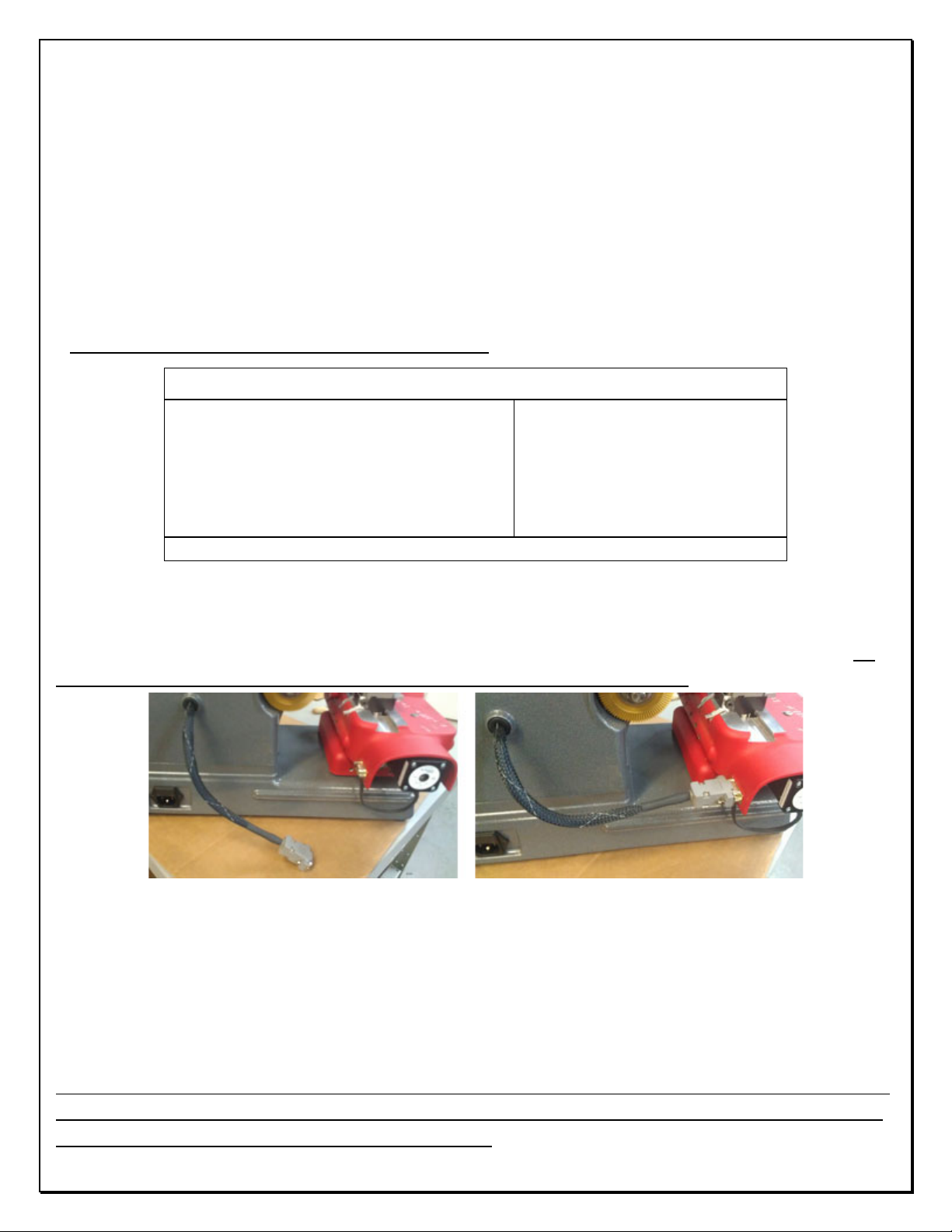
Newer 3D Pro Xtreme key machines have a hard wired motor control cable but on older machines the 9 pin
serial cable exiting the left side of the machine case should only be plugged into the 9 pin serial plug on the
left side of the X table. (see pics below) Be sure to tighten down the two small flathead attaching screws. Do
not plug the 9 pin serial cable into a computer, this will short out the control board.
Computer Hardware Requirements
• Windows XP - SP2 or higher, Windows Vista, 7 and 8 with 2 GB of RAM
• We recommend a 1,500 watt pure sine wave inverter to extend the life of your 3D Pro and laptop.
• If using an inverter to power the 3D Pro, make sure the inverter is properly grounded to the vehicles chassis otherwise
you may experience problems with the operation of the machine. Please follow your inverter manufactures installation
instructions and refer to the “Using an Inverter” page of this manual.
When cleaning key shavings from the machine, please use a brush, please do not use compressed air as doing
so will likely blow shavings into the machine and over time causing problems such as gumming up the axis’ to
where the tables could seize up or cause electrical shorts.

Page 3of 55
The Emergency Stop (On/Off) Button
The Emergency Stop acts as the On/Off
Switch. The “Emergency Stop Button” is
situated on the left hand side of the machine.
In an emergency, hit the button to turn off
the machine. To turn the machine on, twist
the button clockwise and it will pop out. To
turn the machine off, press the button. Note
that if you simply want to cancel a key
cutting process that using the stop button on
the software is a better option.
Software Installation
Installing the Software:
1. Go to LASERKEYPRODUCTS.COM and on the right side of the main home page under Popular
Downloads click 3D Xtreme Software.
2. Next to v15 Click ‘Purchase and Download Now’ then click ‘Add to Cart’ then click ‘Checkout’
then provide Company and other information and click ‘Submit the Information’ and in the
‘Discount Coupon’ box use the coupon code provided in the white envelope received with new
machines and select ‘Use Coupon’ payment method and click ‘Continue’ and then ‘Confirm
Order’ and then ‘Download Now’.
3. The coupon Code will be in the white envelope received with new machines.
(Contact us to purchase codes and obtain the codes download password)
4. Download, extract and Run the downloaded file and follow the on screen instructions
(A video of this procedure can be found on the Xtreme download page)

Page 4of 55
Software Activation
After installation, Double-click your new desktop icon and the License Configuration appears.
(Some downloaded versions will only ask to activate after 3 runs. This is because we allow
users to trial the software and also to let users operate the machine in case they can’t get an
activation code quickly such as if the software is installed after hours.)
1. Read and follow the activation instructions. You will be instructed to email us your site code
and wait for a site key. Site codes are released Monday through Friday 9am – 5pm Central
Standard Time
2. If in the activation window ‘Electronic registration’ or ‘Email Registration Request’ doesn’t
work then copy and paste the site code to your webmail such as Gmail, Yahoo, or Hotmail and
wait for a site key to be sent back to you, then copy and paste the site key in the activation
window and click ‘validate’
3. Once the software is activated you will likely get an error stating that the software cannot
connect to the machine. Follow these next steps on the next page to configure your Device
Manager.

Page 5of 55
Driver Installation
After installing the 3D Pro software, follow these steps to get the machine communicating with the
computer. These steps can also be used if you get a “Motion board not connected” Error. It is
important make sure the machine is hooked up to the computer, powered on and configured in the
device manager properly before starting the software for the machine.
1. Connect power cord to the left side of the 3D Pro and twist out the Red Emergency Stop.
2. Connect USB cable to the right side of your 3D Pro and to any USB port on your computer.
3. Your computer should at this point install the driver automatically, if not the “Found New
Hardware Wizard” will appear. Click install from specific location and Browse to “c:\laser key
products\3d pro windows drivers” and click next and finish. If an unsigned driver warning
appears then select “Continue Anyway”
4. If the “Found New Hardware Wizard” didn’t appear, then open the Device Manager from
the desktop icon labeled “Device Manager” and look for “Other Devices > Motion Controller”
Right Click “Motion Controller” and Click “Update Driver” Choose install from specific location
and Browse to “c:\ laser key products\3d pro windows drivers” and click next then finish. If an
unsigned driver warning appears then select “Continue Anyway”
5. If the driver installed correctly you will “Ports > SSUSB-RS422 Serial Communication
Converter board”. Move onto “Finding the correct COM port” on the next page.
(This is what your device manager should look like after installing the drivers)

Page 6of 55
Driver Configuration
After installing the 3D Pro software and drivers, follow these steps to get the machine communicating
with the computer. These steps can also be used if you get a “Motion board not connected” Error.
1. Open “Device Manager” from the desktop icon and look under “Ports” for “SSUSB-RS422
Serial Communication Converter board” then right-click it and click properties.
2. Under “Port Settings” change
the Bits per second to 57600
3. Click the “Advanced” button and set the COM number to 2
and press OK, and OK again on the Properties page and exit
the Device Manager
4. Close the Device Manager window, then push in the red button on the left side on the
machine and unplug the USB cable going to the computer from the machine, wait 30 seconds
then twist the red button out and plug the USB cable back into your computer and wait 30
more seconds and then start the software.
(This is what your device manager should look like after setting the COM port)

Page 7of 55
Error Connecting
COM Error
If you start your software and the software says “Communications Error” or “Board Not
Found” check these options:
1. Power is going to your 3D Pro from the
power outlet.
2. The emergency stop button is disengaged
(twisted out according to the arrows)
3. The USB cable from the 3D Pro is plugged
into a USB port on your computer.
4. Multiple instances of the 3D Pro software
may be running causing a conflict, check this
by opening Task Manager (Control Alt Delete
on your keyboard and then clicking start Task
Manager.)
Select any items labeled “3D Pro Xtreme.exe”
and then click “End Process”
5. Unplug the USB Cable for 15 seconds, plug
it back in and wait 15 more seconds and then
start the software for the machine.
6. Repeat the Driver Installation and
Configuring COM Port instructions on the
previous pages.

Page 8of 55
If you still get error connecting then right click the desktop icon for the 3D Pro,
click Properties and then click the compatibility tab, set the settings shown below
and press ok. Try to start the software again.
Changing the Cutter and Calibration Stylus
“The Collet” Holds the Cutter or Stylus in the spindle. To
remove the cutter or stylus, first hold the red knurl knob
on the top of the machine sticking up through the lid.
Then press in “spindle stop button” on the front of the
head unit. Now turn the knob on top with your hand until
you feel the spindle stop button press all the way in. Turn
the knob counter clockwise and you will feel the collet
loosen. The cutter or stylus can now be removed.
Machines that do not have the “spindle stop button” will
have a red “knurl knob” underneath the head unit that you
will use together with the top knurl knob to loosen the
“Collet” and remove the cutter.
When replacing the cutter or stylus, insert it into the collet and slide it up until it stops. Press
the spindle stop button in until it catches so you can tighten the collet back up on the cutter, it

Page 9of 55
does not have to be extremely tight, hand tight should be sufficient. If one of the ends of your
TR62.2 double ended Jaw 2 cutter is broken, you will notice that it inserts further into the
collet than normal. This is fine but if it had just broke be sure to click on “Enter” before clicking
on the “Start” button so it will compensate for the new length. Pressing the “Enter” button
causes the machine to recalculate the cutting path.
Changing Tracer
When changing the tracer, tighten the set screw that holds the tracer tip in place in between the two dimples.
The tracing function for duplicating keys works only on metal; don’t try to duplicate plastic keys.
Single ended tracer tip installation:
1. Loosen Set Screw on tracer Swing Arm and remove current tracer
2. Install the Tracer into the Tracer Swing Arm to the installation mark and tighten the set
screw.
(Installation mark indicated by the arrow)
The mark should not be visible after installation
3. Calibrate the tracer after changing tracer tips.

Page 10 of 55
Double Ended tracer tip installation:
When installing a double ended tracer, tighten the set screw that holds the tracer tip in place
in between the two dimples. The tracing function for duplicating keys works only on metal;
don’t try to duplicate plastic keys.
Changing Jaws
Jaw 1 is for High Security keys and the Jaw 2 is
for standard security keys. When changing a
jaw, look behind where the jaw is attached, you
will notice a red “T knob” Turn the “T knob”
counter clockwise to release the lock pin, the
jaw can be now be removed from the table by
sliding it off to the right. Replacing the jaw is
the same operation in reverse order, if the jaw
will not slide into place, make sure the angle of
the lock pin matches the angle of the dovetail,
and lock pin is not protruding (like the one in
the pic)

Page 11 of 55
Calibrating the 3D Pro Xtreme
If you get “Obstruction Detected” errors you may need to calibrate, make sure you are
calibrating with the stylus and not the cutter when calibrating.
Calibrating Cutter for Jaw 1:
1. Clean any shavings or debris from jaw (Any metal
shavings, dirt or grease that the stylus touches will take
an incorrect reading). And open Jaw 1 all the way!
6. Put the Stylus in the collet. The Stylus must be
used to calibrate.
Do not use cutters to calibrate or else your keys will cut
wrong.
This is the Stylus.
3. Make sure the tracer arm is up, if the tracer arm is down, you will receive an error message.
6. On the main screen, click on the
“Operations”
menu and choose “Calibrate Machine”
5. When the window appears asking to “Select
Jaw” insert the correct jaw number in the window,
1 (1, 2, or 3 depending on which jaw you want to
calibrate) as we are calibrating Jaw “1” we would
enter “1” and click “OK”
6. The stylus will touch the jaw in three places. After the procedure is complete it will say
“Update in Progress Please Wait” give it a moment and don’t click anything or it can possibly
freeze the software and you will have to restart it.

Page 12 of 55
Calibrating Tracer for Jaw 1:
1. Always have a “Cutter” or “Stylus” installed while
calibrating the Tracer, do not leave the collet empty or it
will get in the way of the Tracer.
2. Flip the tracer arm down with the “red knurl knob” on
the left side of the head.
3. On the main screen, click on the “Operations”
menu and choose “Calibrate Tracer”
4. When the window appears asking to “Select
Jaw” insert the correct jaw number in the window,
(1, 2, or 3 depending on which jaw you want to
calibrate) as we are calibrating Jaw “1” we would enter “1”
and click “OK”
5. The tracer tip will touch the jaw in three places.
After the procedure is complete it will read,
“Update in Progress Please Wait” give it a moment and
don’t click anything or it can possibly freeze the software
and you will have to restart it.

Page 13 of 55
Calibrating Cutter for Jaw 2:
1. Clean any shavings or debris from
jaw (Any metal shavings, dirt or grease
that the cutter touches will take an
incorrect reading)
2. Close the Jaw 2 so that it is
completely shut with the ‘A’ side facing
the cutter wheel
3. Flip the Shoulder stop up and the Tip
stop down as pictured.
4. On the main screen, click on the
“Operations” menu and choose
“Calibrate Cutter”
5. When the window appears asking to
“Select Jaw” insert the correct jaw
number in the window, (1, 2, or 3
depending on which jaw you want to
calibrate) as we are calibrating Jaw “2”
we would enter “2” and click “OK”
6. The cutter wheel touches the front of
the A side of the Jaw 2 and then moves
to the left and touches the shoulder
stop then goes home.
After the procedure is complete it will
read “Update in Progress Please Wait”
give it a moment and don’t click
anything or it can possibly freeze the
software and you will have to restart it.
Jaw 2 may need minor adjustments to space or depth after calibrating to be correct.
Refer to the section “Checking and Adjusting the “Tracer” for instructions.

Page 14 of 55
There is no tracing for Jaw 2
Calibrating Cutter for Jaw 3:
1. Clean any shavings or debris from jaw (Any
metal shavings, dirt or grease that the stylus
touches will take an incorrect reading). And
open Jaw all the way!
2. Put the Stylus in the collet. The Stylus must
be used to calibrate.
Do not use cutters to calibrate or else your
keys will cut wrong.
3. Make sure the tracer arm is up, if the
tracer arm is down, you will receive an error
message.
4. On the main screen, click on the
“Operations” menu and choose “Calibrate
Machine”
5. When the window appears asking to
“Select Jaw” insert the correct jaw number in
the window, 1 (1, 2, or 3 depending on which
jaw you want to
calibrate) as we are calibrating Jaw “3” we
would enter “3” and click “OK”
6. The stylus will touch the jaw in three
places. After the procedure is complete it will
say “Update in Progress Please Wait” give it a
moment and don’t click anything or it can
possibly freeze the software and you will
have to restart it.

Page 15 of 55
Calibrating Tracer for Jaw 3:
1. Never have a “Cutter” or “Stylus” installed
while calibrating the Tracer, leave the collet
empty or it will get in the way of the Tracer
and cause an error.
2. Flip the tracer arm down with the “red knurl
knob” on the left side of the head.
3. On the main screen, click on the
“Operations” menu and choose “Calibrate
Tracer”
4. When the window appears asking to “Select
Jaw” insert the correct jaw number in the
window, (1, 2, or 3 depending on which jaw
you want to
calibrate) as we are calibrating Jaw “3” we
would enter “3” and click “OK”
5. The tracer tip will touch the jaw in three
places. After the procedure is complete it will
read, “Update in Progress Please Wait” give it
a moment and don’t click anything or it can
possibly freeze the software and you will have
to restart it.

Page 16 of 55
USING JAW 1
“Jaw1” is always used for ALL high security
(laser style keys) except Volkswagen (VW)
The Cutter used most
with Jaw1 is always
the TR2.5 single ended
Cutter:
This is the
“Jaw 1 Tip Stop”
Clamping High Security Keys in Jaw 1
Using the “Tip Stop”
When you selecting High Security keys, the software
will tell you which slot to place the “Tip Stop”
After selecting the key, look under the “Step 2” column
on the home screen, you will find the tip stop number
next “Stop” under the cutter image.
It will read “Tip 1”, “Tip 2”, or “Tip 3”
Place the tip stop in the correct slot, lay the key flat in
the jaw and slide the key forward until it touches the
tip stop then tighten the jaw using the red knob on the
right side of the Jaw 1 and then remove the tipstop.
Warning: Do not forget to remove the tip stop before
tracing or cutting a key. The tracing function for duplicating
keys works only on metal; don’t try to duplicate plastic keys.

Page 17 of 55
Jaw 1 Tipstop Example:
Using the Jaw 1 “Shoulder Stop”
When selecting keys that calls for a
“Shoulder” stop, place the key in the
jaw and slide it forward until the
shoulder of the key is touching the
front of the jaw. Tighten the red knob
to lock the key in place.
Jaw 1 “B” Side
When a Mercedes 2 Track or BMW HU92 2 Track key is selected, it requires that the Jaw 1 “B”
side be used. Open the Jaw 1 and slide the movable side of the Jaw 1 top off the Jaw 1 and
slide it back on with the B side on the left.

Page 18 of 55
Using Jaw 3
(Jaw 3)
When a VAG (HU66) key is selected, it requires Jaw 3 to be used. Insert the key into Jaw 3 and slide
the key forward until the shoulder of the key and tighten the red knob on the right of Jaw 1.
USING JAW 2
When loosening the Jaw 2 clamp be careful not to unscrew the red T knob too far, doing will
cause the moving Jaw 2 top to slide out of the fixed Jaw 2 inner base and will require special
instructions to reassemble.
Changing Jaw 2 Clamp
To change which jaw clamp faces the cutting
wheel all you have to do is loosen the jaw 2 and
firmly twist the jaw 2 in any direction until the
desired jaw clamp is facing the cutting wheel.

Page 19 of 55
Clamping Non-High Security “Shoulder Stop” Keys in Jaw 2
When you select a standard security key
from the menu, the software will tell you
which “Stop” to use, “Shoulder” or “Tip”
This is an example of a Shoulder Stop key.
Slide the key forward until it stops on the
shoulder of the key. Tighten the red knob
on top until the key is clamped firmly.
Clamping Non-High Security “Tip Stop” Keys in Jaw 2
This is an example of a Tip Stop key.
Insert the key into the jaw and raise the
“Tip Stop” slide the key forward until it
touches on the stop.
Remember to fold the “Shoulder” or “Tip” Stop back down before you start to “Trace” or “Cut” a key
Be sure that all keys are inserted completely
into the back (bottom) of the Jaw unless
otherwise specified in the text box on bottom
of the home screen.
The message will appear once the key is
selected, if there are any notes like “clamp
key on milling” it will appear here.
Other manuals for 3D Pro Xtreme
1
Table of contents
Popular Industrial Equipment manuals by other brands

Stahl
Stahl 8579/61 Series operating instructions

Weidmuller
Weidmuller CABTITE Series installation instructions

Erskine Attachments
Erskine Attachments VP48SM Operator's Manual Maintenance Parts Information

WIKA
WIKA F4801 operating instructions

Rodix
Rodix FEEDER CUBE VF-393 manual

Cosasco
Cosasco RBS maintenance