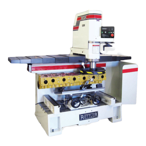
Rottler SA Series User manual

OPERATION AND MAINTENANCE MANUAL
8029 S 200th St. Kent, WA 98032 USA | www.rottlermfg.com | Ph: 253-872-7050 | Fax: 253-395-0230
16.03.2017


ORDERING PROCEDURE
Contact your regional Rottler sales rep for assistance in ordering optional equipment, replacement parts,
or tooling.
If you are unable to contact your regional Rottler sales rep, call the factory at 253-872-7050 and ask to
speak to the parts sales specialist.
Have the following information handy to expedite the ordering process:
1. Your name, business name, and contact number
2. Customer number
3. If you don’t have a customer number, your billing address
4. Shipping address if different from billing address
5. Machine model and serial number
6. Part number and description of what you want to order
7. Preferred method of shipment
8. You may also contact us via e-mail with the above information. Send e-mail requests to:
In some cases you may be requested to send a photo of the part you are ordering if it is a replacement
part, or doesn’t appear in the database.
If you are unsure which part you need to order, contact our service department and ask to speak to one of
our service consultants. They will assist you in determining which part you require.
THERE IS A MINIMUM ORDER OF $25.00
MANUAL SECTIONS
INTRODUCTION
INSTALLATION
SAFETY
CONTROL DEFINITIONS
OPERATING INSTRUCTIONS
MAINTENANCE
TROUBLESHOOTING
MACHINE PARTS
OPTIONS
MSDS


Section 1 Introduction S7A S8A Manual
www.rottlermfg.com
1-1
INTRODUCTION
READ THE SAFETY CHAPTER BEFORE INSTALLING MACHINE. THOROUGHLY UNDERSTAND
ALL SAFETY ISSUES BEFORE OPERATING MACHINE.
ATTENTION OWNER/BUSINESS MANAGER
To validate the warranty on your new Rottler machine, please be sure to sign
and complete the “Installation Report” located in the Installation Chapter of this
manual.
We suggest that the new user of the S7A & S8A read the CONTROL DEFINITIONS to get an idea how
the machine operates.
The Operating Instructions chapter should be read in order to familiarize the user with the actual button
pushing sequences required to carry out a job. These chapters in the manual should be considered an
introduction. As the operators of the S7A & S8A series machines gain experience with using the different
functions of the machine, complicated setups and programs will make more sense.
The rest of the manual contains information and part number reference on xtures, cutting tools, and
machine maintenance. The operator should read and become familiar with these areas as well.

Section 1 Introduction S7A S8A Manual
www.rottlermfg.com
1-2
Description
The model S7A & S8A surfacing machine is a precision, high speed surfacing unit.
The model S7A & S8A can be equipped with tooling and accessories for surfacing most American
passenger car and truck, inline, 90 and 60 degree V-type blocks as well as cylinder heads.
S7A & S8A machines may be readily tooled to resurface a wide variety of engines, including European
and Asian models, as well as perform various other surfacing operations.
This machine is designed for two purposes:
1. The alignment of the deck surface to the pan rails and main bearing locations, as have been done in
the original factory surfacing.
2. A considerable savings in surfacing time and operator involvement as a result of fast block clamping,
and convenient controls.
Change over or resetting time required to set up V-type or in-line engines is a minimum, making this
machine highly suited to the jobber shop where engines cannot be run through, in model lots.
All feeds and rapid travels are power operated and controlled from the conveniently located control panel.
Power required is 230 volt, single phase. This provides power to the variable speed AC motor controller,
the horizontal S.C.R. drive, and various relays and solenoid valves that actuate mechanical controls on
the machine to engage feeds and travels.
Disclaimer
The S7A & S8A Manual (henceforth to be referred to as the “Manual”) is proprietary to Rottler
Manufacturing LLC. (“Rottler Manufacturing”) and no ownership rights are hereby transferred. No part
of the Manual shall be used, reproduced, translated, converted, adapted, stored in a retrieval system,
communicated or transmitted by any means, for any commercial purpose, including without limitation,
sale, resale, license, rental or lease, without the prior express written consent of Rottler Manufacturing.
Rottler Manufacturing does not make any representations, warranties or guarantees, express or implied,
as to the accuracy or completeness of the Manual. Users must be aware that updates and amendments
will be made from time to time to the Manual. It is the user’s responsibility to determine whether there
have been any such updates or amendments. Neither Rottler Manufacturing nor any of its directors,
ofcers, employees or agents shall not be liable in any manner whatsoever to any person for any loss,
damage, injury, liability, cost or expense of any nature, including without limitation incidental, special,
direct or consequential damages arising out of or in connection with the use of the Manual.
Rottler Manufacturing and its employees or representatives are not responsible for any information
regarding nal specications of any workpiece that is created as a nal product when using Rottler
equipment. It is the responsibility of the end user of Rottler equipment to determine the nal dimensions
and nishes of the workpiece that they are working on. Any information regarding nal dimensions and
nishes that appears in any Rottler literature or that is expressed by anyone representing Rottler is to
be regarded as general information to help with the demonstration of or for operator training of Rottler
equipment.
Limited Warranty
Rottler Manufacturing Company Model S7A & S8A parts and equipment is warranted as to materials and
workmanship. This limited warranty remains in effect for one year from the date of delivery, provided the
machine is owned and operated by the original purchaser and is operated and maintained as per the
instructions in the manual.
Tools proven to be defective within the warranty period will be repaired or replaced at the factory’s option.
The products are warranted upon delivery to conform to their published specications and to be free from

Section 1 Introduction S7A S8A Manual
www.rottlermfg.com
1-3
defects in material and workmanship under normal use for a period of one year from shipment. Should a
product not be as warranted, Rottler sole obligation shall be, at its option, to repair, correct or replace the
product or to refund the amounts paid for the Product upon its return to a location designated by Rottler.
No warranty shall extend to rapid wear Products (including tooling) or to Products which have been
subject to misuse (including any use contrary to Rottler instructions), neglect, accident (including during
shipment), improper handling or installation, or subject to any modication, repair or service not certied
by Rottler. Rottler shall not be liable for any consequential, direct or indirect damages or for any other
injury or loss. Buyer waives any right, beyond the foregoing warranty, to make a claim against Rottler.
No warranty is provided for any Products not paid in full.
Merchandise cannot be returned to Rottler without prior approval. Customer must contact the Order
Department or representative to get approval and to be issued a Return Goods Authorization number
(RGR#). Merchandise authorized for return must be returned prepaid. If merchandise is returned with
shipping charges collect, the actual amount of these charges may be deducted from any credit which may
be due the customer. The RGR # assigned by the Order Department should be written on the shipping
label and must appear on a copy of the invoice(s) covering the original shipment. This invoice copy
must be included in the box with the parts. Shipment must contain ONLY those items on the RGR as
approved for return. Merchandise must be received within 10 days of the date of RGR or the RGR will be
canceled. All returned merchandise may be subject to a 20% restocking fee on under $1,000.00 amount
or 10% on any items over $1,000.00. Parts or tooling over 30 days old are considered as customer
property and can only be returned with prior written approval from Rottler Corporation Management and/
or Shipping Department.
The issuance of a RGR DOES NOT guarantee credit - it is only authorization for the return of the
goods. Credit for return merchandise is at the sole discretion of Rottler. Credit will be issued only after
inspection of returned goods.
Tools proven to be defective within the warranty period will be repaired or replaced at the factory’s option.
We accept no responsibility for defects caused by external damage, wear, abuse, or misuse, nor do
we accept any obligation to provide compensation for direct or indirect costs in connection with cases
covered by the warranty.

Section 1 Introduction S7A S8A Manual
www.rottlermfg.com
1-4

Section 2 Installation S7A S8A Manual
www.rottlermfg.com
I
INSTALLATION
Contents
S7/S8 Installation Report ............................................................................................2-2
Installation Procedure.................................................................................................2-6
Location................................................................................................................................. 2-6
Unpacking ............................................................................................................................. 2-6
Shipping Hold Down Bolt .................................................................................................... 2-6
Leveling ................................................................................................................................. 2-6
Air Supply.............................................................................................................................. 2-6
Power Supply........................................................................................................................ 2-7
Grounding ............................................................................................................................. 2-7

Section 2 Installation S7A S8A Manual
www.rottlermfg.com
2-1
ATTENTION OWNER/BUSINESS MANAGER
To validate the warranty on your new Rottler machine, please
be sure to sign the installation report after the installation
technician has installed the machine and veried the machine
is operating correctly and given the operators operation and
maintenance training.
Thank you for your cooperation and the opportunity to be of
service to you.
ROTTLER MANUFACTURING

INSTALLATION REPORT
S7 / S8 A & M SERIES
OFFICE USE ONLY
Route to: Servicer Mgr Accounting Andy Accounting Warranty Exp Date ________
REV 031617
ROTTLER MANUFACTURING MUST HAVE THIS REPORT RETURNED
TO PROPERLY QUALIFY WARRANTY ON EQUIPMENT
Customer:____________________________ Address:_______________________________________
City:_________________________________ State:_____ Zip:_________ Phone:_______________
Country:______________________________
Machine Model:___________ Serial Number:__________ Representative:________________________
MACHINE INSTALLATION: Electrical information MUST be complete to validate this report.
______Follow instructions in this section to uncrate, unpack, and prep machine.
VERY IMPORTANT: Modern design machines contain electronic low voltage
circuitry that provides great advantages and a better machine life. BUT, you
must have an excellent, stable, isolated power supply along with an isolated
ground. If not, electrical noise problems are likely to interfere with machine
operation unexpectedly.
Customer is responsible for providing electricity to machine in a manner that meets the local
electrical code requirements.
______Check machine with precision level and for equal support on feet, then carefully adjust supports to
precisely secure the best average atness of the top table.
______This machine requires 208 to 240V AC 1-phase, 50/60HZ, isolated power supply (measured
between L1 and L2). Current requirement is 15 amps. When using two legs of a three-phase
supply, the voltage from each leg to ground must be between 100-120V AC. Measure the
voltages of the power supply twice during installation (1) _______VAC (2) ________VAC.
IF VOLTAGE IS OUTSIDE THE CORRECT RANGE AT ANY TIME THE
MACHINE WILL NOT OPERATE PROPERLY AND MAY BE DAMAGED.
______Briey describe the isolated ground connection you have made: (Instructions to make a correct
ground are included with the manual
_____________________________________________________________________________
_____________________________________________________________________________
_____________________________________________________________________________

Section 2 Installation S7A S8A Manual
www.rottlermfg.com
2-3
MACHINE START-UP
______BEFORE turning power on to the machine. Check all wires for security by using the correct screw
driver and turning CW until movement stops. Stranded wire can “spread” slightly from vibration
during transport.
______Install electrical component covers inside the electrical enclosure with fasteners provided.
______A dry air supply of at least 80 PSI will use 1 cu. ft./min., maximum. An industrial vacuum system
with a exible 1-1/2” hose should be used on the S7/8--explain the electrical control options for
the vacuum.
______Check the setting of the Relief Valve located at the back of the spindle base. Refer to operators
manual under Maintenance, Air adjustments.
When starting the machine for the rst time, it may move out of control. Make
sure all hands are clear of machine parts. Be ready to press the Emergency
Stop button if needed.
OPERATION
Operator Training
Note: Rotter employees and representatives per company policy are not permitted to provide end
user of Rottler equipment with any OEM specications for the workpiece that is created by end
user using Rottler equipment.
______Explain controls per “Control” section in manual.
______Demonstrate and explain hand feed system (see manual).
______Thoroughly explain the cutter lock and relief system that utilizes the slack in the actuator nut with
air cylinder control. Caution operator of result if a surfacing setting is ever made in the relief up
position.
______Exercise spindle rotation, speed controls, fast travel, feeds, and stop adjustments.
______Have operator perform machine functions (and automatic cycles on applicable machines).
______Remove back of cutter head guard and have operator unclamp, rotate, and clamp cutter inserts.
______Point out the changing and adjustment of insert tool holders per manual.
______Explain optional cutting inserts that are available and their correct application to the type of
material being cut. Explain the use of one versus two inserts.
______Explain availability of optional tooling.
STRESS CAUTION AND PERSONAL SAFETY
______Explain speeds required for carbide, coated carbides, CBN, etc., on specic work piece materials.
______Cutter head change and clearance of guard from cutter level.
______Review operator manual and emphasize safe, methodical operation.
______Parts ordering-show how to refer to manual for part numbers.
MACHINE MAINTENANCE
______Overload device--Micarta key for spindle rotation.
______Inner spindle adjustments (see manual).
______Lubrication (see manual).

Section 2 Installation S7A S8A Manual
www.rottlermfg.com
2-4
CYLINDER HEAD RESURFACING
______Assemble cylinder head xturing in accordance with the manual diagram.
______Have operator clamp head properly, place and adjust jacks and level the work piece with level.
Point out value of a double axis level.
______Use the rst work piece to check dial indicator is set at zero, when cutters touch the surface of the
work piece.
______Set stop to use built-in 4” rapid approach or operator control rapid approach. (Automatic models
only.)
______Explain feed speed combinations for nish on cast iron and aluminum.
V6/8 BLOCK RESURFACING
______Assemble V-block tooling in accordance with the manual diagram.
______Demonstrate the convenience, strengths and weakness of block hold down and leveling capability
where block surfaces require the adjustment.
______Explain adjustments for block angles and rearrangement for large V-blocks, such as 3208 Cats
and adaptations to odd angles such as the Ford super duty truck block.
______Explain procedures to surface protruding cylinder sleeves ush with the block surface.
IN-LINE BLOCK RESURFACING
______Assemble in-line tooling, demonstrating support levels to accommodate a great variety of blocks.
______In addition to adequate hold down force, explain the use of chocking or providing stops that
prevent the block sliding.
______Thoroughly review speeds, feeds, cutter types including shell mills, and general productivity that
the machine is capable of. Make sure operator demonstrates complete understanding.
______Explain cleaning work piece if required and absolute prevention of direct air blast.
______Similarly review all safety precautions and use of emergency stop.
______Explain procedures to surface protruding cylinder sleeves ush with the block surface.

Section 2 Installation S7A S8A Manual
www.rottlermfg.com
2-5
General remarks on machine performance, adjustments as received and any further organization or parts
required to complete the installation.
____________________________________________________________________________________
____________________________________________________________________________________
____________________________________________________________________________________
____________________________________________________________________________________
____________________________________________________________________________________
____________________________________________________________________________________
____________________________________________________________________________________
____________________________________________________________________________________
____________________________________________________________________________________
____________________________________________________________________________________
____________________________________________________________________________________
____________________________________________________________________________________
Instructions given to:___________________________________________________________________
Sales/Service Engineer: _______________________________________________ Date_____________
Shop Foreman/Superintendent or Owner: _________________________________ Date_____________
Once completed send this form to:
Rottler Manufacturing
attn: Service Manager
8029 S 200 St
Kent, WA 98032 USA
Alternately you may send this form via fax or e-mail:
fax: [+1] 253-395-0230
e-mail: [email protected]

Section 2 Installation S7A S8A Manual
www.rottlermfg.com
2-6
Installation Procedure
Location
The productivity of this machine will depend a great deal on it’s proper initial installation, particularly the
means by which cylinder blocks/heads are lifted into the machine as well as the material handling to and
from other operations in your shop.
The proper loading arrangement and location for your S7A & S8A machine is extremely important.
A slow travel (6 to 10 feet / min.) power hoist, operated from either a bridge crane or a jib crane
arrangement works very well. A 1000-lb. hoist is generally adequate for lifting the engine block. An air
hoist with speed control makes an ideal method for fast, convenient loading.
If some production surfacing with this machine is anticipated, and the cylinder blocks/heads are not
directly loaded and unloaded from a conveyor, we recommend considerable attention be given to the
crane so that it covers an adequate area to allow the operator to back up and remove cylinder blocks/
heads without cluttering up his own area. If two machines are to be operated by one operator, we
recommend that the open faces be placed at right angles to each other, with the machines about three
feet apart.
Unpacking
Use care in removing the crate from the S7A & S8A machine, do not use force on any part of the spindle
unit.
Remove the tool box, parallels, and optional tooling, located at the lower portion of the machine and
completely clean these articles, as well as the machine base pads and upper table, with solvent. Rust
inhibitor is applied to the machine at the time of shipment, any of this inhibitor left on the machine will
result in considerable collecting of cast iron dirt.
Shipping Hold Down Bolt
Remove cover (#7036E) from the rear of the spindle base by removing it’s four mounting screws. Remove
the bolt located in the front bottom of the spindle base. Replace the cover and tighten the four mounting
screws.
Leveling
Four square head set screws (502-1-12A), jam nuts (502-1-12F), and chamfered washer (502-1-12), are
provided with the machine for leveling. Insert the screw and nut at the base support points, being careful
that the screw point seats in the washer.
Use a precision level and level the upper table within .0005” per foot in both directions and make sure that
the machine weight is equally supported at the four support points of the base.
Air Supply
It is very important the air source for the S7A and S8A machine be moisture free. Water and oil in
the line will result in early cylinder and valve failure. Our recommendation is the installation of a water
trap at the machine.
Attach a 100 PSI air source to the appropriate intake at the air lter on the side of the rear control
enclosure.

Section 2 Installation S7A S8A Manual
www.rottlermfg.com
2-7
Power Supply
This machine requires 208 to 240 VAC single phase, 50/60 Hz, (measured between L1 and L2). Current
required is 15 amps.
When using two legs of a three phase supply the voltage from each leg to ground must be between
100-120 VAC. Connect per following electrical hook-up instructions. If the voltage is outside this range
the machine will not operate properly and may be damaged.
Do not attempt to attach three phase voltage to this machine. The
three phase spindle motor receives it’s power from a three phase
variable frequency drive in the rear enclosure. The frequency inverter is powered by single phase.
Connect single phase wiring to the breaker switch as shown below.
Grounding
This machine must be connected to a good earth ground. Connect
the earth ground wire to grounding bar inside the electrical enclosure.

Section 3 Safety S7A S8A Manual
www.rottlermfg.com
I
SAFETY
Contents
Safety Information.......................................................................................................3-1
Safety Instructions for Machine Use .........................................................................3-1
Electrical Power...........................................................................................................3-3
Machine Operator........................................................................................................3-4
Emergency Procedure ................................................................................................3-5

Section 3 Safety S7A S8A Manual
www.rottlermfg.com
3-1
Safety Information
For Your Own Safety Read This Instruction Manual Before Operating This Machine.
This is the safety alert symbol. It is used to alert you to potential personal injury hazards. Obey
all safety messages that follow this symbol to avoid possible injury or death.
DANGER indicates an imminently hazardous situation which, if not
avoided, will result in death or serious injury.
WARNING indicates a potentially hazardous situation which, if not
avoided, could result in serious injury.
CAUTION indicates a potentially hazardous situation which, if not
avoided, may result in minor or moderate injury.
CAUTION used without the safety alert symbol indicates a potentially
hazardous situation which, if not avoided, may result in property damage.
Safety Instructions for Machine Use
This machine is capable of causing severe bodily injury
ONLY A QUALIFIED, EXPERIENCED OPERATOR SHOULD OPERATE THIS MACHINE. NEVER
ALLOW UNSUPERVISED OR UNTRAINED PERSONNEL TO OPERATE THE MACHINE. Make sure
any instructions you give in regards to machine operation are approved, correct, safe, and clearly
understood. Untrained personal present a hazard to themselves and the machine. Improper operation will
void the warranty.
KEEP GUARDS IN PLACE and in proper working order. If
equipped with doors, they must be in the closed position when the
machine is in operation.

Section 3 Safety S7A S8A Manual
www.rottlermfg.com
3-2
KEEP WORK AREA CLEAN. Cluttered areas and benches invite accidents.
KEEP CHILDREN AND VISITORS AWAY. All children and visitors should be kept a safe distance from
work area.
WEAR THE PROPER APPAREL. DO NOT wear loose clothing, gloves, rings, bracelets, or other jewelry
which may get caught in moving parts. Non-Slip foot wear is recommended. Wear protective hair
covering to contain long hair.
ALWAYS USE SAFETY GLASSES. Also use face or dust mask if cutting operation is dusty. Everyday
eye glasses only have impact resistant lenses, they are NOT safety glasses.
DO NOT OVER-REACH. Keep proper footing and balance at all times.
USE THE RECOMMENDED ACCESSORIES. Consult the manual for recommended accessories. The
use of improper accessories may cause risk of injury.
CHECK DAMAGED PARTS. Before further use of the machine, a guard or other part that is damaged
should be checked to determine that it will operate properly and perform its intended function. Check
for alignment of moving parts, breakage of parts, mounting, and other conditions that may affect its
operation. A guard or other part that is damaged should be properly repaired or replaced.
NEVER OPERATE A MACHINE WHEN TIRED, OR UNDER THE INFLUENCE OF DRUGS OR
ALCOHOL. Full mental alertness is required at all times when running a machine.
IF AT ANY TIME YOU ARE EXPERIENCING DIFFICULTIES performing the intended operation, stop
using the machine! Then contact our service department or ask a qualied expert how the operation
should be performed.
DO NOT MODIFY OR ALTER THIS EQUIPMENT in any way. If modications are deemed necessary, all
such requests must be approved and/or handled by Rottler Manufacturing. Unauthorized modications
could cause injury and/or damage to machine and will void the warranty.
SAFETY DECALS SHOULD NEVER BE REMOVED. They are there to convey important safety
information and warn of potential hazards.
ALL LOCAL SAFETY CODES AND REGULATIONS should be followed when installing this machine.
ONLY QUALIFIED PERSONAL should perform service on the electrical and control systems.
When boring the machine is capable of throwing metal chips over 10- feet from the cutting area. Always
use the guards. Eye protection must be worn at all times by the operator and all other personnel in the area
of the machine.

Section 3 Safety S7A S8A Manual
www.rottlermfg.com
3-3
No list of safety guidelines can be complete. Every piece of shop
environment is different. Always consider safety rst, as it applies to
your individual working conditions. Use this and other machinery with caution and respect. Failure to
follow guidelines could result in serious personal injury, damage to equipment or poor work results.
Electrical Power
All electrical power should be removed from the machine before opening the rear electrical enclosure.
In the event of an electrical short, grounding reduces the risk of electric shock by providing a path of least
resistance to disperse electric current.
Electrocution or a re can result if the machine is not grounded correctly. Make sure the ground is
connected in accordance with this manual. DO NOT operate the machine if it is not grounded.
This manual suits for next models
2
Table of contents
Other Rottler Industrial Equipment manuals

Rottler
Rottler SAD Series User manual

Rottler
Rottler SG80AII User manual

Rottler
Rottler H85A User manual

Rottler
Rottler SG10XY User manual

Rottler
Rottler SG9A User manual

Rottler
Rottler DA-4SB Assembly Instructions

Rottler
Rottler P69 User manual

Rottler
Rottler SG8 User manual

Rottler
Rottler VR9 User manual

Rottler
Rottler SM Series User manual