Laser SB20 Quick start guide

RIGGING MANUAL
SB20 Rigging Instructions
The SB20 rigging instructions are a guide to rigging your boat. Due to production supplies
certain parts may be slightly modified from those shown. This instruction manual is not a
guide to sailing your craft and it should not be considered suitable for the task of learning
to sail a boat.
CONTENTS
•Glossary
•Basic boat parts
•Maintenance
•Sail numbers
•Shroud layout
•Assembly of the mast
•Raising the mast
•Setting up the mast
•Rigging the boat
•Launching and keel lowering
•Recovery of the boat and towing

GLOSSARY
Aft: Back of the boat
Backstay: Support at the back of the boat to the top of the mast used to
control the mast bend, and support the mast.
Bow: Front of the boat
Burgee: Wind indicator usually a flag
Batten: A thin stiffening strip in the sail to support the leech
Boom: A spar at the foot of the sail
Cleat: A fitting used for holding / securing ropes
Clew: Back lower corner of a sail
Cunningham: an eye in the sail above the tack of the sail
Foot: Bottom of the sail
Forestay: The wire supporting the mast at the bow of the boat
Gennaker: Isometric sail hoisted when sailing downwind
Gennaker pole; the Pole, which extends to fly the gennaker tack from.
Gunwale: The outermost edge of the boat
Gudgeon: Fitting on the transom and rudder used to hang rudder
Granny rail; The stainless steel rail on the side of the boat.
Gnav: Used to control the leech twist and shape of the sails can be referred to
as Vang.
Head: Top of sail
Halyard: A rope or wire used to lower or hoist sails
Jib: Front sail
Jib Sheet: Control rope for the jib
Leech: Trailing edge of the sail
Luff: The front edge of the sail
Mast Heel: The fitting at the base of the mast
Mast step; The fitting on the boat where the mast heel is located
Shrouds: Wire supporting the mast
V1 / D3 – Main shroud
V2 / D4 – Cap shrouds
V1 – Lower shrouds
V2 – 2nd set of lowers
Spreaders; Metal struts placed in pairs to support the mast side ways and
control the bend in the mast.
Stern: Back of the boat
Stem fitting: Stainless fitting at the bow which the forestay attaches.
Tack: Forward lower corner of the sail
Traveller: The track that runs side to side that controls the mainsail side ways
in the boat. Used in conjunction with the mainsheet.
Vang: Otherwise known as the Kicking strap, Gnav.

USEFUL BOAT TERMINOLOGY
Gennaker
Pole
Tack
D1 / Lower
D2 shroud
Clew
Gennaker
Main
shroud
V1 / D3
Cap shroud
V2 /
D4
Backsta
y
Head
Cunningham control
Gnav control
Gennaker Halyard
Jib Halyard
Pole out control
Gennaker tack line

MAINTENANCE AND SERVICE
• Keep the equipment clean by frequently flushing with fresh water. In
corrosive atmospheres stainless parts may show discoloration around
screw holes and rivets, this is not serious and can be removed with a
fine abrasive.
• Excess water should be removed from the hull.
• Ropes, rigging and fittings should be checked at regular intervals for
wear and tear, including the keel winch gear.
• All moving parts should be lightly lubricated to avoid jamming, i.e.,
McLube, Dry Teflon or a dry silicone based spray.
• Inspect shackles, pins and fittings – tape up to stop snagging, coming
undone.
• When refastening screws do not re – use Nilock nuts more than three
times.
• Do not leave heavy loads on the blocks when not in use as this can
distort the bearings.
• Seals on the main hatch and small hatch covers should checked
regularly and replaced if damaged.
• Damaged or worn parts should be replaced.
• Trailers should be rinsed with fresh water and checked at regular
intervals. It is recommended that the trailer be serviced annually.
• Gel coat damage should be repaired as soon as possible. Gel coat
specifications and repair kits available from Laser Direct.
• UV light will cause fading to some components and fittings, a cover is
recommended to reduce the UV degradation.

SAIL NUMBER POSITIONING
1. Lay the sail on a flat surface starboard side up.
2. Position the 1st number ( 3 ) 150mm in from the leech and 60mm
below the draft line.
3. The numbers should run parallel to the draft line.
4. Numbers should be 60mm apart.
150mm
from leech
60mm apart
5. Turn over the sail
6. Position the GBR
starting with the R
180mm from the leech
7. The GBR is 60mm
above the draft line.
8. The letters are 60mm
apart.
9. Position the sail nos
60mm underneath and
parallel to the numbers
on the opposite side.
10.The numbers should be
put on so that they are in
line with the numbers on
the opposite side of the
sail.
11.This will be approx 200mm from the leech.

12.The starboard side GBR
should be positioned
60mm above the port
side letters and parallel
to them.
13.The letters should sit
above the port side
letters starting with the G
14.The gap between the
letters is 60mm.
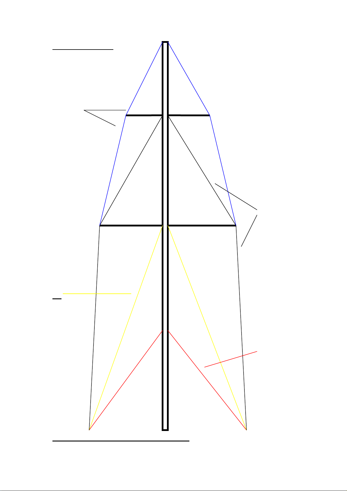
SHROUD LAYOUT
V2 / D4 (Cap shroud )
VI / D3 main
shroud
D2
D1
Lowers
D shrouds are diagonals, V shrouds are verticals
V1 / D3 is a continous length, V2 / D4 is a continous length.

ASSEMBLY OF THE MAST
1. The mast will be supplied flat packed and will
require some tools to assemble:
- Posidrive screw driver
- Small adjustable spanner x 2 ( or mole
grips ) Care required if using mole grips
as these can mark the fittings)
- Electrician / small screwdriver
- Tape measure 5meters
- Rig tension gauge (recommended)
- Plastic tape
2. The shrouds and halyards will all be in position
on the mast and will just require unwrapping.
3. The 2 sets of spreaders and the backstay whip
are taped to the mast.
4. The backstay whip has 3 pre-drilled holes and
is attached to the crane at the top of the mast.
The screws are supplied in the crane.
5. The spreader is fixed with no
adjustment. They are marked port
and starboard and simply attached
with two clevis pins and rings.
Ensure that these are taped up.
6. Measure the V2 / D4 ( Cap shrouds ) and adjust the bottle screw to give
a distance of 4440mm from the bearing surface of the pin to the bearing
surface of the T terminal on this shroud. This measurement may vary
slightly and is a starting guide, the objective is to achieve 4” prebend.

7. Fit the V2 / D4 ( Caps)shrouds and the V1 / D3 ( main shrouds) to the T
terminals first and then to the spreaders. The Ferrules on the main
shrouds are located as shown. Locate the Main shrouds into the spreader
end by removing the clevis pin and slotting into position. The clevis pin
then fits to the bottle screw on the Cap shroud.
Caps
4440mm
8. Tape up the main shroud as
shown. This holds the feral in
position whilst fully taping the
end of the spreader assembly.
9. Lock the bottle screw by
inserting a small screwdriver
and turning anti clockwise.
10. V1 / D3 shrouds - Adjust the bottle
screws so that they are the same length
and showing approx 20mm of thread.
(loose, this will be set up once the rig is
raised and tensioned)
11. Fit the D2 and the D1shrouds and
repeat getting the lengths equal.
12. Ensure that all pins and rings are
taped up. The mast is now ready for stepping.
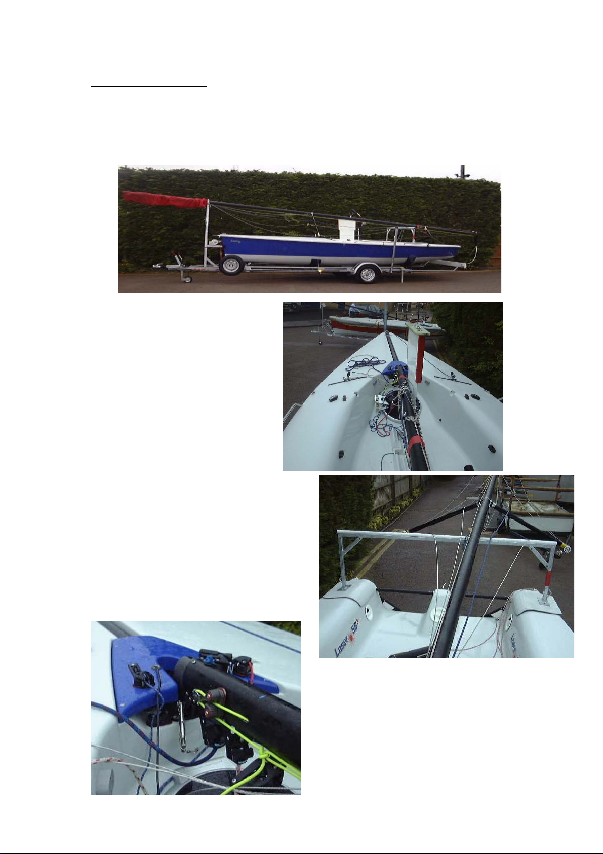
RAISING THE MAST
1. The rig in transit position. The mast support is positioned at the granny
2.
. The mast and cradle are
ack of
ft
4. ould always
5. hould not
. The mast step bolt should then be
rails. This will be moved to the back of the boat when raising the mast.
The trailer should be chocked or lower the rear supports before
assembly of the mast.
3
moved aft. The mast
cradle should be
positioned at the b
the boat as shown, and
then the mast is moved a
to position the mast heel to
the step.
The mast sh
be positioned on the port
side of the keel.
The Lifting post s
astbe in position for lifting the m
as it could foul the rigging.
5
tightened so that the Nilock on the
nut is engaged.
Table of contents
Other Laser Boat manuals


Popular Boat manuals by other brands


PURSUIT
PURSUIT OS 335 owner's manual

Boston Whaler
Boston Whaler CONQUEST 345 owner's manual

Jeanneau
Jeanneau SUN ODYSSEY 41 DS owner's manual

Meridian
Meridian 490 Pilothouse owner's manual

Advanced Elements
Advanced Elements AdvancedFrame Expedition AE1009 owner's manual

Robo Marine Indonesia
Robo Marine Indonesia GEOMAR user manual


