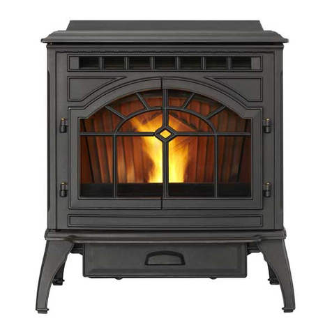
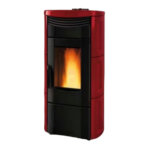
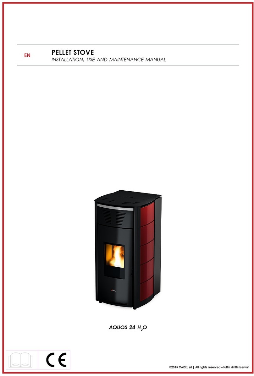
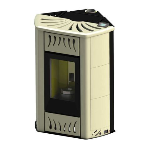
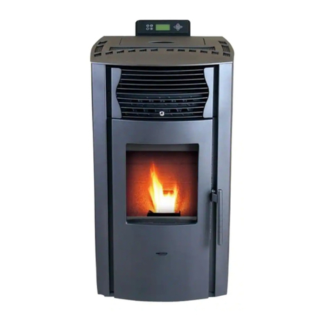
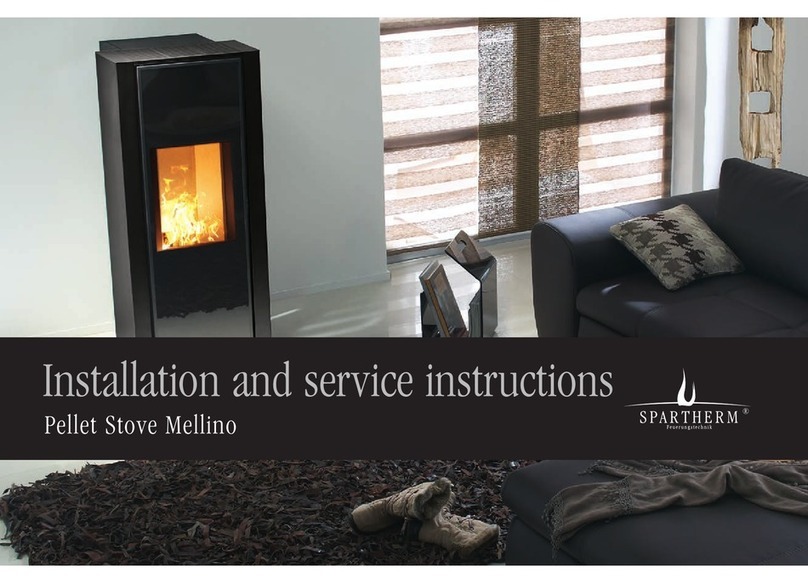
LASIAN AUDAX 6 KW Operating manual

LASIAN Heat Technology S.L.
PELLET STOVE
6-8-10-12 KW
USER AND INSTALLATION MANUAL

COD. 83119L.01EN
09//2016
2

COD. 83119L.01EN
09//2016
3
THANK YOU FOR CHOOSING!
On behalf of LASIAN. Heat Technology S. L we thank you for trusting us, and have chosen a LASIAN Air
stove. Now you have a heat source of biomass with a compact design and easy installation.
oPlease read this manual carefully because it will furnish important instructions regarding the
safe installation, use and maintenance.
oInstallation of Air LASIAN stoves must be carried out by qualified personnel, following the
manufacturer's instructions and in accordance with current standards.
oImproper installation can cause damage, so the importance of this document which is part of
the product.
oThe manufacturer is not responsible for the misuse of it.

COD. 83119L.01EN
09//2016
4
STOVES
6/8/10/12 KW
6 kW
8 kW
10 kW
12 kW

COD. 83119L.01EN
09//2016
5
DECLARATION OF CONFORMITY
In compliance with the requirements of the COUNCIL OF THE EUROPEAN UNION
The Company LASIAN Tecnología del Calor, S.L.
with C.I.F. B50141894, and registered address at:
Políg. Ind. Las Norias, parcela nº 7 - 50450 MUEL (Zaragoza) - SPAIN
Manufacturer of boilers for production of heating and A.C.S,
Brand: LASIAN
In its different models:
AUDAX 6 KW,
AUDAX 8 KW,
AUDAX 10 KW,
AUDAX 12 KW,
WE HEREBY DECLARE, under our sole responsibility, that the above mentioned products are
manufactured in accordance with the following directives and standards:
2004/108 CE and 2014/30/UE
2006/95 CE
Regulation UE nº 305/2011 Construction Products
EN 60335-1; EN 60335-2-102;
EN 61000-3-2; EN 61000-3-3;
EN 50366; EN 55014-1; 55014-2
EN 14785
Muel, 28th January 2016
The characteristics and manufacture date on each unit are indicated in the technical documentation that accompanies each
stove.

COD. 83119L.01EN
09//2016
6
INDEX
1. CARE OF THE MANUAL AND HOW TO CONSULT IT 8
2. IMPORTANT INSTRUCTIONS 9
3. TECHNICAL DATA 10
4. FUEL 11
4.1 CERTIFIED PELLET 12
4.2 WHAT DO YOU HAVE TO KNOW ABOUT THE PELLET 12
4.3 USER SETTINGS DEPENDING ON THE PELLET THAT HAS BEEN USED 13
5. INSTALLATION 14
5.1 CHOICE OF LOCATION 14
5.2 UNPACKING 14
5.3 DOMESTIC FIRE PREVENTION 15
5.3.1- MINIMUM SAFETY DISTANCES 15
5.3.2- FLOOR PROTECTION 16
5.3.3- MEASURES TO BE TAKEN ON TO CROSS WALLS AND CEILINGS 17
5.4 DUCT OR CHIMNEY 17
5.4.1- GENERAL NOTES 17
5.4.2- CHOICE AND CALCULATION OF THE DUCT 19
5.4.3- USE OF A TRADITIONAL TYPE CHIMNEY 20
5.4.4- USE OF EXTERNAL CHIMNEY 21
5.4.5- FLUE DUCT ENDING 21
5.5 VENTILATION AND FRESH AIR INTAKE 22
5.6 ELECTRICAL CONNECTION 23
6. INSTRUCTIONS OF THE CONTROL PANEL 24
6.1 USER MENU 1 25
6.1.1- INFORMATION 25
6.1.3- ADJUSTMENT OF THE POWER FUNCTIONING 26
6.1.4- PELLET MANUAL LOAD 26
6.1.5- ADJUSTMENT OF THE ROOM THERMOSTAT 26
6.1.6- PELLT LOAD CALIBRATION 27
6.1.7- COMBUSTION FAN CALIBRATION 27
6.2 USER MENU 2 28
6.2.1- ROOM FAN ADJUSMENT (AIR) 28
6.2.2- SCHEDULE PROGRAMMING (CRON) 28
6.2.3- TIME AND DATE OF THE WEEK (OROL) 31
6.2.4- REMOTE CONTROL 32
6.2.5- CLEANING RESET (RCLR) 32
6.2.6- TECHNICAL MENU (TPAR) 32
7. USE AND WORKING OF THE STOVE 32
7.1 ADVICE AND WARNING 32
7.2 PELLET LOAD 33
7.3 FIRST POWER-UP 33

COD. 83119L.01EN
09//2016
7
7.4 STATES OF WORKING 35
7.4.1- STOVE STOPPED 35
7.4.2- IGNITION 35
7.4.3- STOVE IS ON (NORMAL WORKING) 35
7.4.4- MODULATION (“MOD”) 35
7.4.5- PERIODIC CLEANING BURNER (“PCLR”) 36
7.4.6- STANDBY 36
7.4.7- IGNITION RECOVERY (“REC”) 36
7.4.8- SWITCH OFF (“OFF”) 36
8. PROBLEMS, MESSAGES AND ALARMS 36
8.1 PROBLEMS 37
8.2 MESSAGES 37
8.3 ALARMS 38
9. CLEANING AND MAINTENANCE 40
9.1 MAINTENANCE TABLE 41
9.2 DISPOSAL OF ASHES 42
9.3 BRAZIER CLEANING (BURNER) 42
9. HEAT EXCHANGER CLEANING 43
9.5 COMBUSTION CHAMBER CLEANING 43
9.6 SMOKE CHAMBER CLEANING 44
9.7 UNLOAD INSTALLATION CLEANING (CHIMNEY) 44
9.8 GLASS DOOR CLEANING 44
9.9 FUEL HOPPER CLEANING 45
9.10 ANNUAL INSPECTION 45
*WARRANTY CONDITIONS

COD. 83119L.01EN
09//2016
8
1. CARE OF THE MANUAL AND HOW TO CONSULT
IT
Take care of this manual and keep it in an easily accessible place.
Should the manual be misplaced or ruined, request a copy from your installer or directly from the manufacturer
giving the identification details of the product.
The proper functioning of the stove depends on largely that the user know its operation and he know all times what
has to do. For this reason, the manual includes an index on pages 6 and 7 in order to the user can find easily the
sections to resolve some questions and doubts that may arise.
When we read or check this manual, we will note:
“Bold text” requires particular attention.
In some cases, it can be used capital letters or increase the font size to draw attention to some
paragraphs.
Text in “italics” is used to draw your attention to other paragraphs in this manual or any additional
explanation.
In some cases, even it could be combined two or more of indicated resources above. This would be the
case when we refer to the reading of other chapters to supplement or consult some information:
Example: (check paragraph “4- FUEL”)
SYMBOLOGY
SYMBOL
MEANING
INFORMATION DISPLAYED
ATTENTION!
It is used to provide information that obliges or prohibits to
do something, and whose failure can have serious
consequences.
INFORMATION
It is used to provide useful information to the user, which can help
to improve the functioning of the stove, and / or understand better
certain situations and know what to do.

COD. 83119L.01EN
09//2016
9
2. IMPORTANT INSTRUCTIONS
Installation and use of the product should be in accordance with the manufacturer's instructions, obeying
European, national and local regulations where the product is installed.
This instruction manual has been prepared by the manufacturer and it is an essential part of the product. Should
the stove be sold or transferred, it should always be accompanied by the manual as it contains information that is
necessary for the buyer and all persons involved in the installation, maintenance and use of the product.
Carefully read and understand the instructions and technical information contained in this manual before
proceeding with the installation, use and maintenance of the product. Familiarization of the instructions in this
manual ensures the safety of people and a longer life performance of the product.
In case of problems or misunderstandings of the instructions, contact the installer.
The manufacturer disclaims any liability for damage caused by failure to read the rules and instructions for
installation, use and maintenance listed in the book of instructions, unauthorized product modification or use of
non-original spares.
Installation, electrical connection, maintenance and repairs must be performed only by a qualified, authorized
person and with a proper knowledge of the product. Before the installation, check the flatness of the floor where
the product will be installed. The installation must be carried out following the instructions of chapter “5 –
INSTALLATION”, many of which are manufacture advices and others are taken from the current local standards
at the time of writing the manual, so if there would be any modification of the standard, or the stove is installed in a
place that is subject to different rules, it will be necessary to adapt the installation of the stove to these standards.
Use of appropriate gloves is advised when handling coated parts to avoid leaving traces that are difficult to remove
in the first cleaning. The assembly of the stove should be carried by at least two people.
Connect the stove to the mains only after connecting the chimney.
Never use liquid fuels to start the stove.
Provide sufficient ventilation during the installation. In case of malfunction, the fuel supply will be interrupted.
Restart the product only after having the cause of the problem solved. Stop using the product in case of failure or
malfunction. Do not lift the grating which lies inside the fuel hopper. Any accumulation of unburned fuel in the
burner resulting from misfire must be removed before ignition.
While the stove is working, it is recommended not to touch the hottest parts like handle, door, chimney exhaust
and glass. Due to the heat of the glass door, pay attention to keep anyone not involved in the installation away
from the stove. Inform persons in the vicinity of the stove of the necessary precautions while the product and
possible products are working.
Do not place non heat-resistant objects on the stove or within the prescribed minimum safety radius of the stove
(check chapter “5.3.1- MINIMUN SAFETY DISTANCES”).
Do not open the door during operation, or start the stove if the glass is broken.
For terms, limits and exclusions refer to the warranty certificate supplied with the product. The manufacturer may
make changes deemed appropriate to the stove documentation without notice, to pursue a policy of constant
development and constant renewal of the product.
This document is property of the manufacturer and cannot be transferred in whole or in part to any third party
without the written consent of the company. All rights reserved.
DIRECTIVES AND STANDARDS
All our products are manufactured according to the following directives and standards:
2004/108/CE y 2014/30/UE
2006/95/CE
Regulation UE nº 305/2011
EN 60335-1; EN 60335-2-102;
EN 61000-3-2; EN 61000-3-3;
EN 50366; EN 55014-1; 55014-2
EN 14785

COD. 83119L.01EN
09//2016
10
3. TECHNICAL DATA
The technical label indicates data and performance of the appliance.
The handling, removal or lack of technical label hinders any installation and maintenance, since it is not possible
to identify the product. In case of damage, request a duplicate of it to the service center. Given the importance of
the label, we recommend installing the stove respecting the distances so that it is always visible.
MODEL
AUDAX 6 kW
AUDAX 8 kW
AUDAX 10 kW
AUDAX 12 KW
Nominal thermal output
min./max.
kW
3,5 – 6,4
3,9 – 8,2
3,7 – 10,4
3,8 - 12
Efficiency at
nominal/reduced termal
output
%
86 - 87%
86 – 93%
85 –89%
85 – 88%
Average fumes
temperature at nominal
thermal output
ºC
216
181
203
209
Consumption hourly
min./max.
kg/h
0,8 - 1,5
0,8 – 1,7
0,8 – 2,1
0,8 – 2,4
Tank capacity
kg
13
13
15
24
Electric absorment in
work
W
80 - 150
80 - 150
80 - 150
80 - 150
Flue duct
Ø
80mm
80mm
80mm
80mm
Weight
kg
74
79
83
118
Dimensions
LxPxH
460x490x865
460x490x865
460x490x900
514x505x1115

COD. 83119L.01EN
09//2016
11
DIMENSIONS AND COMPONENTS MODELS AUDAX 6-8-10-12 kW
4
1
6
5
2
3
4. FUEL
The stove has been just designed to burn WOOD PELLETS which meet the requirements set by
DIN plus / ENplus A1 certification.
Wood pellet is a fuel made from compacted sawdust extracted from the remains of the production and processing
of dried natural wood; the compactness of the product is guaranteed over time by a natural substance contained in
the wood: the lignin. The typical form resembling small cylinders is achieved by wire drawing.
DIMENSIONS
6 kW
8 kW
10 kW
12 kW
H (mm)
880
880
915
1115
h1 (mm)
865
865
900
1100
COMPONENTS
1
Door handle
2
ø40 Air intake
3
Electrical outlet
4
ø80 Flue duct
5
Control panel
6
Hopper lid

COD. 83119L.01EN
09//2016
12
4.1 CERTIFIED PELLET
On the market there are various types of pellet with quality and features that change depending on the kind of
production and type of wood materials used, but in this case the stove has been designed to exclusively operate
with DIN plus / ENplus A1 pellet, which guarantees the good performance of the stove.
DINplus is a voluntary brand issued by a third body that certifies the pellet produced and marketed respects the
requirements of the Austrian standard Önorm M 7135, one of the most demanding standards in the market.
Whereas, ENplus is a voluntary brand issued by a third body that certifies the pellet produced and marketed
respects the requirements of the standard EN 14961-2.
The requirements of dimensions and other properties required by these standards are shown in the following table:
Pellet dimensions according to EN 14961-2 and ÖNORM M 7135
Requirement
Unit
DINplus
ENplus A1
Diameter *
mm
4D < 10
D06 : 6 1
D08: 8 1
Length *
mm
5 x D
3,15 L40
Net calorific value
MJ/kg (w.b)
Q ≥ 18 (MJ/kg in d.b)
16,5 Q19
Moisture
% (w.b)
10
Ash
% (d.b)
0,5
0,7
*For stoves is only allowed:
Maximum diameter: 6 mm
Maximum length: 30 mm
Other diameters and lengths are valid for use in boilers.
4.2 WHAT DO YOU HAVE TO KNOW ABOUT THE PELLET
A certified pellet under any of the two previous standards (DIN plus / EN plus A1) would be the best guarantee for
the proper functioning of the stove, but still, there are pellets that meet and even exceed the requirements widely,
and others are at the limit the certification allows, so the stove will behave differently with a fuel and other.
Also keep in mind that throughout the heating season, consumption of pellet shoots up, especially in cold winters,
and fuel reserves can run out of pellet, so producers have to produce more with a wood than may not be like it was
in early winter, and even though you buy the pellet of the same brand and quality than the previous pellet, it does
not have the same characteristics.
Storage and handling of the pellet by the user, is also very important, because if it is not done properly, we can
vary the calorific characteristics (increase of moisture) and physical characteristics (increasing the proportion of
sawdust) of the fuel.
When a new batch of fuel is begun it is advisable to control the operation of the stove (check
paragraph “4.3 USER SETTINGS DEPENDING ON THE PELLET THAT HAS BEEN USED”).
Fuel must be stored in a dry place and special attention must be paid to the handling of the
sacks in order to avoid grinding them and form sawdust.

COD. 83119L.01EN
09//2016
13
If the fuel does not come properly marked, the corresponding certificate should be required.
Facing a not identified pellet, or if we consider for various reasons that it could changed its characteristics, we can
make use of the following tips to know if the fuel is suitable or not for its use:
AVOID the use of pellets with different dimensions to those indicated.
AVOID the use of pellet too hard or too soft.
AVOID the use of pellet which show granules of not typical colours of wood, or excessively dark.
AVOID the use of fuel containing powder of mixed sawdust, resins or chemical, additional or binder
substances.
AVOID the use of wet fuel.
The choice of unsuitable fuel causes:
- Accumulation of fuel in the burner.
- Bad combustion.
- Burner and gas flue duct dirtying.
- Increase in fuel consumption.
- Decrease in performance.
- Does not guarantee the normal operation of the stove.
- Glass dirt.
- Production of unburned granules.
- Need for more cleaning and maintenance of the stove.
The presence of moisture in the fuel increases the volume of the capsules and breaks them causing:
- Malfunctions of the load system.
- Accumulation of fuel in the burner.
- Bad combustion.
The use of fuel not according to the manufacturer's instructions can damage the stove and
compromise its performance, resulting in the invalidation of the warranty and in the end of the
liability of the manufacturer on the product.
4.3 USER SETTINGS DEPENDING ON THE PELLET THAT HAS BEEN USED
As we have already explained in the previous section is clear that when the fuel that we use in the stove is
changed, this behavior may be different, and although the electronic board have a system which adjusts the
changes in conditions to achieve always a good combustion, it is advisable to observe the behavior of the stove
every time you start a new batch of fuel.
The characteristic that has more influence in the way the pellet is burned is the percentage of ash left when is
burned. Normally, a higher percentage will need more air to make the combustion, even it could be necessary to
reduce the fuel quantity, if the pellet requires more time than usual to be burnt completely.
It could also be the opposite case, although it is less usual, that provided fuel to burns faster than normal.
In both cases the user has, within what we call "USER MENU 1", two functions which readjust the stove to burn in
the best way possible the pellet that is being used at every time ( see paragraphs “6.1.6- PELLET LOAD
CALIBRATION” and “6.1.7- COMBUSTION FAN CALIBRATION”).
To establish some criteria to help the user to choose how to use these settings, we can apply the following criteria:
If the stove is not able to remain switched on continuously for 8-12 hours because the pellet accumulates
in the burner, this is because the air supplied by the fan is not enough for the amount of pellets that we are
loading.
In this case, we can do two things:
- Increasing the amount of supplied air with positive steps of the fan (check 6.1.7).
- Decreasing the fuel load with negative steps in pellet calibration (check 6.1.6).

COD. 83119L.01EN
09//2016
14
If during operation of the stove fuel burns so fast that there is almost never flame in the burner (even it can
appears the “Er03” alarm), it is because the air supplied by the extractor is excessive for the amount of
pellets that are loading.
In this case, we can do two things:
- Decreasing the amount of supplied air with negative steps of the fan (check 6.1.7).
- Increasing the fuel load with positive steps in pellet calibration (check 6.1.6).
Before changing the fan and pellet calibration, it is necessary to make sure everything is
correct: installation, maintenance and cleaning, etc. For this we can check the chapter 8-
ALARMS, MENSSAGES AND PROBLEMS”.
It is preferable to change first the fan calibration, so the pellet load also modify the output of the
stove.
5. INSTALLATION
The installation of LASIAN Air Stoves must be only carried out by qualified staff,
following the manufacturer's instructions and in accordance with all standards
and regulations that are applicable. Otherwise, the manufacturer is not liable for
any accident.
5.1 CHOICE OF LOCATION
It is forbidden to install the stove outside (exposed to the atmospheric agents) or in wet areas,
as well as in bedrooms, locations with bath or shower and in places where there is another
heating unit if they do not have the suitable dimensions and devoid of an adequate airflow.
When we choose the location of the stove, we will try that the route until the flue gas duct connection were as short
as possible, and flue gas can be discharged easily (check paragraph “5.4- DUCT OR CHIMMEY”).
Since in both, the stove and in the flue gas ducts it can be reached high temperatures, you have to follow certain
rules and safety recommendations to prevent possible fires and dangerous situations, so to make the installation
check paragraph “5.3- DOMESTIC FIRE PREVENTION”.
To ensure the air supply for the combustion in the stove, and keep a suitable ambient conditions, it has to keep in
mind everything with reference to ventilation which is explained in paragraph “5.5- AIR INTAKE AND
VENTILATION.”
We must also have a suitable power point near the stove (check paragraph “5.6- ELECTRIC CONNECTION”), so
that the installation has finished, the power cord that comes with the stove can be connected and disconnected
easily.
To make easier the loading of the pellet and the access to the control panel, as well as the maintenance or any
intervention in the stove, it will be necessary to leave a minimum distances above and around it. A reference to
follow might be the ones described in paragraph “5.3.1 MINIMUM SAFETY DISTANCES”, although at least on the
right side of stove, it would be convenient to leave a minimum distance of 400 mm. in order to access to the rear
side of the stove.
Installation and use of the product should be in accordance with the manufacturer's
instructions, obeying European, national and local regulations where the product is
installed.
5.2 UNPACKING
Unpack the product carefully so it does not get damaged or scratched. Remove from the tank of the stove the
accessory bag (it contains the legs of the stove, the power cord, the remote control, for the models which take it
and the instructions manual) and from the combustion chamber possible pieces of polystyrene or cardboard used
to block the removable parts, etc.
Also keep out of reach of children parts of the packaging (plastic bags, polystyrene, etc.) that could be potentially
dangerous and dispose according to the existing laws.

COD. 83119L.01EN
09//2016
15
5.3 DOMESTIC FIRE PREVENTION
- The installation and use of the stove must comply with the manufacturer's instructions and technical and safety
standards that correspond it. Otherwise, the manufacturer is not liable for any accident.
- For the installation of the stove it must be taken in account the paragraph: "5.3.1- MINIMUM SAFETY
DISTANCES".
- If the floor is made of combustible material, the stove must be placed on a platform of fireproof material in the
way indicated in paragraph: 5.3.2- "FLOOR PROTECTION".
- When a chimney crosses a wall or ceiling it is necessary to take on specific measures, which we can see in
paragraph: 5.3.3- "MEASURES TO BE TAKEN ON TO CROSS WALLS AND CEILINGS".
- When installing the flue duct or chimney, it must be taken into account several technical standards and
regulations, which are necessary for a proper operation of the stove and play an important role to prevent
possible fires "5.4.1- GENERAL NOTES".
- It is recommended to keep out of the heat source area (at least at 1.5 meters) all flammable or combustible
items such as wooden beams, furniture, curtains, flammable liquids, etc. In the event that there are flammable
or heat sensitive coatings in the surrounding space, a protective layer of insulating and not combustible
material must be placed.
- It is necessary to carry out periodic cleanings of the stove and flue ducts, as soot and other combustion
residues accumulated, could eventually ignite.
- If the flue should catch fire, be equipped with a suitable systems for suffocating the flames or request help
from the fire service.
5.3.1- MINIMUM SAFETY DISTANCES
The following figures show the minimum safety distance that must always be guaranteed.
INSTALLATION IN ANGLE (mm)
WALL INSTALLATION (mm)
Distancias de seguridad de material inflamable
mm
minimum distance air from flammable posterior wall
P = 200
minimum distance air from flammable side wall
L = 200
front distance of flammable material
R = 1500

COD. 83119L.01EN
09//2016
16
DISTANCE FROM FALSE CEILINGS OR
FLAMMABLE CEILINGS (mm)
DISTANCE FROM THE FLUE DUCT OF
FLAMMABLE WALLS INSTALLATION (mm)
5.3.2- FLOOR PROTECTION
In case of heat sensitive or flammable floors is necessary to use a baseboard or floor protection which separate
the stove from the floor.
We will use for this a fire resistant material such us a Steel sheet, marble or tiles. Whatever type of protection is
chosen, it must be able to withstand without deforming or breaking the weight of the stove.
The thickness will not be never less than 2 mm, and it must protrude at least 300 mm from the front, and at least
150 mm from the sides and the rear side of the stove (see fig. 5.1 and 5.2).
Fig. 5.1
Fig. 5.2
2 mm protection
Floor
Stove

COD. 83119L.01EN
09//2016
17
5.3.3- MEASURES TO BE TAKEN ON TO CROSS WALLS AND CEILINGS
To expel the gas duct outside, the flue duct has to cross some walls of the place where is installed, even
sometimes, it must pass through more than a stay up to the ridge.
The size of the holes to practice depends on the duct diameter and the enclosure material to pass through. Once
the duct has been installed, the space between the hole and the duct must be with mineral-based insulating barrier
(rock wool, ceramic fiber), with a nominal density greater than 80 kg/m3.
Minimum holes to practice and insulation thickness table:
Diameter flue duct pipe [mm]
Insulation
thickness [mm]
Ø80
Up to 24 kW
Ø 100
From 28 kW
Diameter holes to be done [mm]
Wall in flammable wood or with
flammable parts
100
280
300
Wall or ceiling in cement
50
180
200
Wall or ceiling in brick
30
140
160
5.4 DUCT OR CHIMNEY
To expel outside the flue gas produced during the combustion in the stove, we need to connect it to a flue duct or
chimney.
5.4.1- GENERAL NOTES
For the installation of the chimney, it must be taken into account the following points:
Each stove must have its own duct or chimney, in which it cannot been connected any other fireplace, stove, boiler
or any kind of extractor (fig. 5.3).
The chimney route will be as short as possible and it always will search the maximum vertical direction. The
diameter will be chosen according to the guidelines of paragraph “5.4.2- CHOICE AND CALCULATION OF THE
DUCT”.
The inner section should be uniform, preferably circular: square or rectangular sections must have rounded edges
with a radius of at least 20 mm; regular bends without discontinuities, deviations from the axis no greater than 45°
(Fig. 5.4).
It is forbidden the installation of dampers or valves that could block the passage of flue gas.
Avoiding horizontal sections of chimney because this leads to fouling problems and it requires the cleaning of
these sections more frequently. In case of being unavoidable, it will give a minimal upward inclination in the
direction of gas flow, and a "T" will be installed in the changes of direction to clean the ducts without disassembly it
(see Fig. 5.5).
To install the duct certain distances and safety regulations must be observed (see paragraph “5.3- DOMESTIC
FIRE PREVENTION”).
The flue duct must always finish its route upright, and shall have on top a device called cowl (see paragraph
“5.4.5- FLUE DUCT ENDING”).
Always carry out the unloading installation so that periodic cleaning is assured without having to dismantle any
part. It is advisable that the flue is equipped with a solid material collection chamber and possible condensations
beneath the mouth of the duct to be easily opened and inspected from the door hermetically (see Fig. 5.5).
The draw of the smoke is forced thanks to an extractor that keeps the combustion chamber in
depression and all the discharge pipes under a slight pressure. It is required to verify that this
extractor is installed correctly and completely tight and firm, both for performance and safety.

COD. 83119L.01EN
09//2016
18
Fig. 5.3
Fig. 5.4
Fig. 5.5
Yes
Yes
Direction of
cleaning
Direction of
cleaning
Direction of cleaning
Sealing plug

COD. 83119L.01EN
09//2016
19
5.4.2- CHOICE AND CALCULATION OF THE DUCT
For the chimney route, it must be taken into account the following advices:
Pipes of painted aluminum-clad steel (minimum thickness of 1.5 mm), stainless steel (AISI 316) or enameled steel
(minimum thickness of 0.5 mm) can be used.
Hoses are admitted if they meet the specifications set by law (stainless steel with a smooth inner wall) and male-
female connectors must have a minimum length of 50 mm.
To carry out the flue duct, the ducts to be used may have a nominal diameter between 80 mm and 150 mm, to
choose according to the needs and characteristics of the stove and installation.
In the following table are shown the limitations for the duct diameters more used, considering that the
maximum and minimum lengths are counted from the "T" output of the stove, and it is from there where it
should be increased the diameter of the duct if it is necessary (see fig. 5.6):
LIMITATIONS
WITH Ø 80 mm PIPE
WITH DOUBLE-
WALLED Ø 100 mm
PIPE
Minimum length (mandatory in vertical)
1.5 m
2m
Maximum lenght (with two 90° bends)
4.5 m
8m
For installations more than 1200m above the
sea
1.100 m
-
Length of horizontal sections with minimum
5% gradient
2 m
2 m
Fig. 5.6
The maximum length allowed for each diameter has been calculated for ducts installed vertically, with
a maximum of 2 curves of 90º and practically without horizontal section (only for through the wall if it
were necessary).
If the chimney route was different, it would have to calculate the "equivalent load loss" of the
installation, using the table below.
KIND OF ROUTE OR ACCESSORY LENGTH TO SUBTRACT OF TOTAL ALLOWED
90º Bend 1 meter
45º Bend 0.5 meters
Horizontal section 1 meter
Diagonal section 0.5 meters
“T” Accessory 1 meter
Connection Ø80>Ø100
Tee

COD. 83119L.01EN
09//2016
20
The “Equivalent load loss” of an installation, is the result of the sum of total meters to install (which
includes the losses of the two bends and the “T” connection), plus the additional losses resulting from the
application of the above table.
The sum of these losses should be less, or at most equal to the maximum allowable length which is
indicated in the table of limitations. If it were not so, we must increase the diameter of the duct to install:
Equivalent load loss Maximum allowable length
5.4.3- USE OF A TRADITIONAL TYPE CHIMNEY
If you wish to use an existing chimney it is strongly recommended that you have it checked by a professional
chimneysweep to ensure that it is completely airtight. The reason for this is that the smoke, because it is slightly
pressurized, can infiltrate any cracks in the flue and escape into living spaces.
If upon inspection you find that the chimney is not completely sound, it is recommended that you insert piping
made of new material.
If the existing chimney is wide enough, we recommend a pipe with a maximum diameter of 150 mm; it is also
recommended that you insulate the chimney flue. Fig. 5.7 and 5.8 represent the solutions to be adopted if you
want to use an existing chimney.
Fig. 5.7 Fig. 5.8
Cowl
Inspection doors
Insulating – See Table
Tee
CLOSING FLANGE
Sealing flange in stainless
steel or aluminum
Fresh air intake with non-
closable grille
Inspection
This manual suits for next models
3
Table of contents