manuals.online logo
Brands
  1. Home
  2. •
  3. Brands
  4. •
  5. Harman
  6. •
  7. Pellet Stove
  8. •
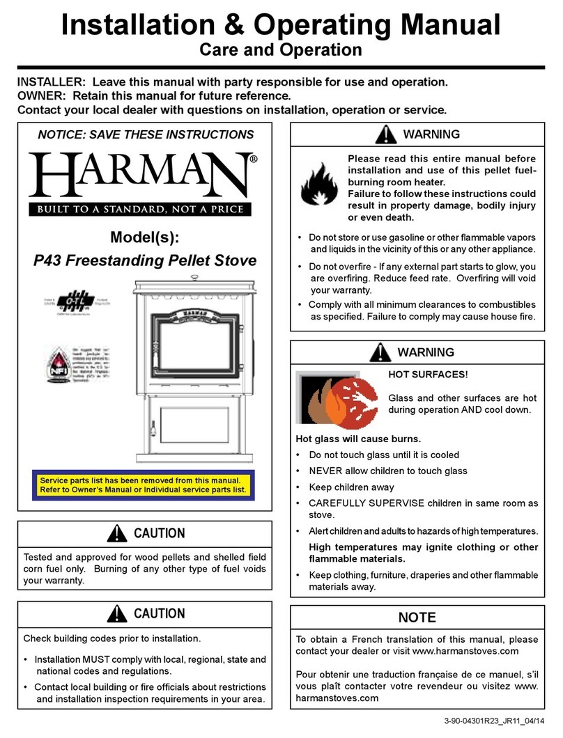
  9. Harman P35I User manual

Harman P35I User manual

Other manuals for P35I

4

This manual suits for next models

1

Other Harman Pellet Stove manuals

Harman PELLET P61A Installation instructions

Harman

Harman PELLET P61A Installation instructions

Harman Absolute43 User manual

Harman

Harman Absolute43 User manual

Harman XXV Freestanding Pellet Stove User manual

Harman

Harman XXV Freestanding Pellet Stove User manual

Harman Accentra Freestanding Pellet Stove Installation instructions

Harman

Harman Accentra Freestanding Pellet Stove Installation instructions

Harman P35I User manual

Harman

Harman P35I User manual

Harman PP38+ Installation instructions

Harman

Harman PP38+ Installation instructions

Harman P43 User manual

Harman

Harman P43 User manual

Harman Advance Freestanding Pellet Stove Installation instructions

Harman

Harman Advance Freestanding Pellet Stove Installation instructions

Harman P68 User manual

Harman

Harman P68 User manual

Harman P43 Installation instructions

Harman

Harman P43 Installation instructions

Harman P68 Installation instructions

Harman

Harman P68 Installation instructions

Harman PC45 Installation instructions

Harman

Harman PC45 Installation instructions

Harman PP38+ Installation instructions

Harman

Harman PP38+ Installation instructions

Harman Advance Pellet Stove Installation instructions
Harman

Harman Advance Pellet Stove Installation instructions

Harman XXV User manual

Harman

Harman XXV User manual

Harman The Accentra Pellet Stove Installation instructions

Harman

Harman The Accentra Pellet Stove Installation instructions

Harman P68 Installation instructions

Harman

Harman P68 Installation instructions

Harman Advance Pellet Stove Installation instructions

Harman

Harman Advance Pellet Stove Installation instructions

Harman Accentra Freestanding Pellet Stove Installation instructions

Harman

Harman Accentra Freestanding Pellet Stove Installation instructions

Harman XXV Installation instructions

Harman

Harman XXV Installation instructions

Harman PP38 plus User manual

Harman

Harman PP38 plus User manual

Harman XXV Installation instructions

Harman

Harman XXV Installation instructions

Harman P43 Installation instructions

Harman

Harman P43 Installation instructions
Harman P61 User manual

Harman

Harman P61 User manual

Popular Pellet Stove manuals by other brands
Palazzetti ECOFIRE MIRIAM Description & operation

Palazzetti

Palazzetti ECOFIRE MIRIAM Description & operation

Quadra-Fire MTVI-E2-MBK owner's manual

Quadra-Fire

Quadra-Fire MTVI-E2-MBK owner's manual

Quadra-Fire MTV-E2-CSB owner's manual

Quadra-Fire

Quadra-Fire MTV-E2-CSB owner's manual

vicenza V4.5 Installation and operating instructions

vicenza

vicenza V4.5 Installation and operating instructions

Palazzetti JP Series PRODUCT TECHNICAL DETAILS

Palazzetti

Palazzetti JP Series PRODUCT TECHNICAL DETAILS

Travis Industries Avalon 900 PS owner's manual

Travis Industries

Travis Industries Avalon 900 PS owner's manual

Astra P-7 user manual

Astra

Astra P-7 user manual

Heatilator ECO-ADV-PS35 owner's manual

Heatilator

Heatilator ECO-ADV-PS35 owner's manual

MCZ VIVO 90 COMFORT AIR 9 M1 Use and installation guide

MCZ

MCZ VIVO 90 COMFORT AIR 9 M1 Use and installation guide

Cadel aquos 24 h2O Installation, use and maintenance manual
Cadel

Cadel aquos 24 h2O Installation, use and maintenance manual

Ferroli GEMMA Installation, use and maintenance manual

Ferroli

Ferroli GEMMA Installation, use and maintenance manual

pleasant hearth PH35PS Series owner's manual

pleasant hearth

pleasant hearth PH35PS Series owner's manual

SMG Comfort Bilt HP50GC Operator's manual

SMG

SMG Comfort Bilt HP50GC Operator's manual

Quadra-Fire CB1200M-MBK owner's manual

Quadra-Fire

Quadra-Fire CB1200M-MBK owner's manual

England's Stove Works 25-EP Installation & operation manual
England's Stove Works

England's Stove Works 25-EP Installation & operation manual

Flame FP-45 owner's manual

Flame

Flame FP-45 owner's manual

Spartherm Mellino Installation and service instructions

Spartherm

Spartherm Mellino Installation and service instructions
United States Stove American Harvest 6039 owner's manual

United States Stove

United States Stove American Harvest 6039 owner's manual

manuals.online logo
manuals.online logoBrands
  • About & Mission
  • Contact us
  • Privacy Policy
  • Terms and Conditions

Copyright 2025 Manuals.Online. All Rights Reserved.

13-90-774256_R4 • 03/21
P35i Zero Clearance Cabinet Instructions
Part #1-00-774257
Assembly Instructions:
Contents of Kit;
(1) Top Panel
(1) Bottom Panel
(2) Side Panels
(1) Rear Panel
(1) Flue Pipe Insulation Wrap
(2) Wire Wraps
(48) #8 X 1/2” Tek Screws (Self-Tapping)
Dimensions
7-5/16”
(186mm)
Ø 3-7/8”
98mm
16-15/16”
(430mm)
24-3/4”
(629mm)
5-1/4”
(133mm)
28-1/16”
(714mm)
Ø 6-1/16”
156mm
26-1/2”
(673mm)
8-1/4”
(210mm)
7-7/8”
(200mm)
24-3/4”
(629mm)
1”
(25mm)
Tools Needed;
Cordless Drill or Screw gun
1/4” Driver Bit
Small pair of “C clamp” locking
pliers are helpful.
23-90-774256_R4 • 03/21
• Begin with the bottom panel lying at on the oor or
workbench. Place it with the writing facing upward.
Figure 1.
Use care when installing tek screws, do not strip the
holes.
CAUTION
!
• Stand the other side panel up to the left side of the
bottom, with the electrical box knockout at the bottom
rear corner, and secure it the same way.
• The top panel can now be placed onto the sides, with the
bend going out over the outside of the side panels. Align
the holes and secure with tek screws. Figure 3.
Figure 1 - View of the bottom panel
• Stand a side panel up to the right side of the bottom,
with the (un-used) electrical box knockout in the top rear
location. Notice the bend at the rear of the cabinet will
make the corner and at the front it will be bent outward to
makethefacingange.Lineuptheholesandsecurethe
side panel to the bottom with screws. Figure 2.
Figure 2 - View of the side panel
• Stand the rear panel up to the rear of the cabinet, be
sure the arrow is pointing upward. Secure the rear panel
to the outside of the cabinet. Figure 4.
Figure 4 - View of the rear panel
Figure 3 - View of the top panel
Bend on top goes outside
the side panels.
ZC Box Assembly
33-90-774256_R4 • 03/21
Electrical Installation (If Needed)
A knockout is provided in the left rear corner of the zero
clearance cabinet to install an electrical outlet (not supplied)
if desired. Be sure to ground the receptacle to the zero
clearance cabinet if installed. Figure 8.
Flue Rough-In Support Kit
Flue rough-in support #1-00-774283 installs in the zero
clearancecabinetandprovidesauestubmountingsurface
which will be in the exact position of the stub when it is on
the insert mounting frame. Figure 9.
If you have not yet purchased the insert, order stub kit #
1-00-674040. This kit includes a 4” pipe stub, gasket and
mountingbolts.Ifyoudohavetheinsert,removetheue
stub from the mounting frame. Install the exhaust stub onto
the support using the bolts and nuts from the support kit.
Install with bolts passing upward, through the support plate
andtheangenutsonthetop.Ifinstallingtheoutsideairkit,
install the stub from the kit onto the left side of the support.
It is not necessary to install the gaskets on the support
plate, however you will need them for nal attachment.
Next, using 8 tek screws, install the rough in support into
the cabinet. You can now run your venting and air intake
and permanently attach them to their respective stubs. Be
sure to properly secure both, the venting and the outside air
pipe, so that they cannot move when you remove the rough-
in support. When all of the construction is completed, and
you are ready to install the insert, remove the support plate,
leaving the stubs in place. Install the insert mounting frame
and bolt the stub(s) and gasket(s) to the frame.
IMPORTANT! Install the stub gasket between the stub
and the mounting frame.
Figure 9
Figure 8
Electrical Knockouts
43-90-774256_R4 • 03/21
Framing
• Theangearoundthefrontofthecabinetmustmateuptothenishedface.Usetheholesintheangetosecurethe
cabinet. Alternately, extra mounting holes can be drilled through the cabinet where desired. Figure 5.
Framing and other combustible
materials are permitted to touch the
outside walls of the cabinet.
Top View
ThisFlangeMUSTbeFlushwith
Finished Facing.
Follow vent manufacturers
guidelines and maintain proper
clearance to combustibles.
Figure 5
• Whendeterminingthedepthinyourframingdimensions,thethicknessofthenishmaterialandanybackersmustbe
taken into consideration. Figure 6.
• Todeterminetheproperoorprotection,thehearthmustextendaminimum;15-1/4”(US)or27-1/4”/692mm(CAN)
fromthenishedwallface.
NOTE: Combustible materials may contact any exterior surface of the cabinet.
Side View
Consider the wall nish material
thickness when planning the depth
of your framing. The image at right
shows adequate space for 1/2”
drywall.
1/2” space (Example)
ThisFlangeMUSTbe
Flush with Finished Facing.
Figure 6
Framing leveling
bolts will fit here
Insert Mounting Frames securing holes
Mounting Frame Securing Points - Once framing
is complete secure the mounting frame into the ZC
box using 2” sheet metal screws proper installation.
Figure 5.
53-90-774256_R4 • 03/21
Raised Hearth Installation
Whenconstructingwitharaisedhearth,besuretobuildinsupportforthecabinet.Thisoormaterialcanbeusedunderthe
cabinet only, or it can be applied onto the hearth as well. The image at right shows 3/4” plywood extending onto the hearth.
Notice the support members at the front and rear of the cabinet.
Thehearthnishmaterialcannotexceed1/4”abovethetopedgeofthecabinetbase.Seedetailbelow.Alsoremember,the
hearthneedstoextendtoprovidethepropercombustibleoorprotection.Figure7.
3/4” plywood decking
Support
Members
1/2” Finish Material
(Example)
Mantel must be a minimum of
12 inches above the cabinet top.
It is recommended to install 3/4”
plywood under the entire cabinet,
as a minimum for support.
Hearth nish material should be ush
with, or no more than 1/4” higher than the
top edge of the cabinet base. Exceeding
this height will prevent proper installation.
Ceramic Tile
(Example Only)
Figure 7
Framing leveling
bolts will fit here
Insert Mounting Frames securing holes
Mounting Frame Securing Points - Once framing
is complete secure the mounting frame into the ZC
box using 2” sheet metal screws proper installation.
Figure 5.
63-90-774256_R4 • 03/21
Venting
Follow vent manufacturers guidelines and maintain proper clearance to combustibles.
You must use a minimum 12” vertical section
ofventpipeattachedtotheuestub.
Vent pipe within cabinet must be wrapped with the
included insulation to prevent overheating of motors and
components. Secure the insulation with the wire wraps.
Must use an approved wall pass-through or thimble where
venting penetrates an external wall.
Start the insulation with this point in the rear
oftheuestub.Theinsulationwillwraptwo
times around the pipe. Secure it in place
with the two pieces of wire supplied.