Lassco Wizer Spinnit FM 2 User manual

USER’S MANUAL
Spinnit FM 2 Manual Paper Drill
Before operating this equipment, please read these
instructions completely and keep these operating
instructions for future reference.
485 Hague Street, Rochester, NY 14606 U.S.A.
Tel: 585-436-1934 Fax: 585-464-8665
www.lasscowizer.com info@lasscowizer.com
Serial Number:
Date of Purchase:
Dealer:
Address:
Telephone Number:
-
R

Table Of Contents
1 - Introduction
1.1
1.2
1 - Introduction
1.1 - Your New FM-2 Paper Drill
1.2 - Shipping Damage Inspection
Remove the machine from the carton and inspect for
any shipping damage. If any damage is present, report
the damage to the carrier immediately; failure to do so
may void any warranties.
Page 01
Page 01
R
Page 01
Your New FM-2 Paper Drill...................
Shipping Damage Inspection...............
2 - Safety
2.1
2.2
2.3
Page 02
Page 03
Page 04
Safety Instructions................................
Warning Labels.....................................
Grounding Instructions.........................
3 - Setting Up Your Machine
3.1
3.2
3.3
3.4
3.5
3.6
3.7
3.8
Page 05
Page 05
Page 06
Page 06
Page 07
Page 07
Page 08
Page 08
Loose Items Inventory..........................
Accessories Warning............................
Uncrating and Removing From the
Pallet....................................................
Installing the Leveling Feet..................
Attaching the Paper Side Stops...........
Attaching the Chip Bag........................
Choosing and Installing the Pattern
Bar.......................................................
Electrical Instructions...........................
4 - Operation
4.1
4.2
4.3
4.4
4.5
4.6
4.7
Page 09
Page 09
Page 10
Page 10
Page 11
Page 12
Page 12
Protective Guard..................................
Drill Bit Removal and Installation.........
Adjusting the Table Height...................
Adjusting the Back-Gauge Assembly...
Traversing the Table.............................
Drilling Procedures...............................
Tips on Drilling......................................
5 - Maintenance
5.1
5.2
Page 13
Page 13
Safety....................................................
Annual Lubrication................................
6 - Trouble Shooting Guide
6.1
Page 14
Determining the Cause and Correction
to Certain Problems..............................
Thank you for your purchase of the Spinnit FM-2 Paper
Drill.
We ask that you take a moment to ll in the serial
number and other information on the front cover of the
manual. Please keep this manual as a reference for
future use.
For parts and service, please contact the Lassco-Wizer
Dealer from whom you purchased the machine. If you
require assistance in locating a Lassco-Wizer Dealer
please contact our customer service department at 585-
436-1934. Please have the model of your machine and
the serial number when you call.
If you wish to write to us, send correspondence to:
Lassco-Wizer
Attn: Customer Service
485 Hague Street
Rochester, NY 14606

2 - Safety
2.1 - Safety Instructions
Page 02
All operators must read and understand the Users
Manual including all safety instructions before using this
equipment. Failure to fully understand the safety
instructions can result in personal injury. If after reading the
manual you are still uncertain about use, please
contact the dealer from whom you purchased the
machine for assistance. If you need contact information for
a Service Technician nearest you please call
585-436-1934.
SAFETY OF THIS EQUIPMENT IS THE RESPONSIBILITY
OF THE USER(S).
Please read and follow all warning labels on your machine.
INDUSTRIAL AND IN-PLANT USE ONLY. This equipment
is for use in industrial and in-plant areas only and must be
operated by trained and qualied personnel.
WEAR PROPER APPAREL. Do not wear loose
clothing , gloves, neckties, rings, bracelets, or other jewelry
which may get caught in moving parts. Non slip footwear
is recommended. Wear protective hair covering to contain
long hair.
Keep hands clear while operating machine.
ALWAYS USE SAFETY GLASSES. Also use face or dust
mask if drilling operation is dusty. Everyday eyeglasses only
have impact resistant lenses, they are NOT safety glasses.
KEEP GUARDS IN PLACE and in working order.
Always disconnect the power before servicing this machine.
Service should only be performed by a QUALIFIED TECH-
NICIAN.
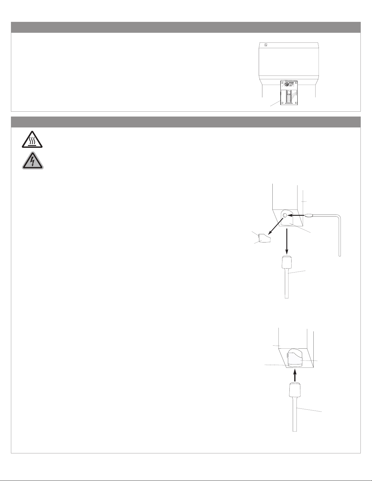
Always turn the machine to off mode and wait for the drills
to stop spinning before installing or removing drill bits. Keep
hands away from drills when operating. PLEASE NOTE
THAT THE DRILL BITS MAY BE HOT AFTER USE. PRO-
CEDE WITH CAUTION WHEN CHANGING THE DRILL
BITS.
DON’T USE IN DANGEROUS ENVIRONMENT. Don’t use
this machine in damp or wet locations, or expose it to rain.
Keep work area well lighted.
THIS MACHINE IS DESIGNED FOR ONE PERSON OP-
ERATION. Never operate the machine with more than one
person.
KEEP CHILDREN AWAY. All visitors should be kept a safe
distance from the work area.
MAKE WORKSHOP KID-PROOF with padlocks or master
switches.
DON’T FORCE MACHINE. It will do the job better and safer
at the rate for which it was designed.
USE RIGHT MACHINE. Don’t force tool or attachment to
do a job for which it was not designed.
MAINTAIN MACHINE WITH CARE. Keep tools sharp and
clean for best and safest performance. Follow instructions
for lubricating and changing accessories.
REMOVE ADJUSTING KEYS AND WRENCHES. Form
habit of checking to see that keys and adjusting wrenches
are removed from machine before turning it on.
KEEP WORK AREA CLEAN. Cluttered areas and benches
invite accidents.
DISCONNECT MACHINE before servicing; when changing
accessories, such as drill bits, drill blocks, and the like.
REDUCE THE RISK OF UNINTENTIONAL STARTING.
Make sure the power switch is in the off position before
plugging in.
USE RECOMMENDED ACCESSORIES. Consult the us-
er’s manual for recommended accessories. The use of im-
proper accessories may cause risk of injury to persons.
NEVER STAND ON MACHINE. Serious injury could occur
if the machine is tipped.
DON’T OVERREACH. Keep proper footing and balance at
all times.
CHECK DAMAGED PARTS. Before further use of the ma-
chine, a guard or other part that is damaged should be care-
fully checked to determine that it will operate properly and
perform its intended function--check for alignment of moving
parts, binding of moving parts, breakage of parts, mount-
ing, and any other conditions that may affect its operation.
A guard or other part that is damaged should be properly
repair or replaced.
NEVER LEAVE MACHINE RUNNING UNATTENDED.
TURN POWER OFF. Don’t leave machine until it comes to
a complete stop.

AVERTISSEMENT: NE PAS EXPOSER
À LA PLUIE ET NE PAS UTILISER DANS
LES EMPLACEMENTS HUMIDES
2 - Safety
2.2 - Warning Labels
Page 03
WARNING: DO NOT EXPOSE TO RAIN
OR USE IN DAMP LOCATIONS.
English French

Page 04
In the event of a malfunction or breakdown, grounding provides a path of least resistance for electric current to re-
duce the risk of electric shock. This tool is equipped with an electric cord having an equipment-grounding conduc-
tor and a grounding plug. The plug must be plugged into a matching outlet that is properly installed and grounded
in accordance with all local codes and ordinances.
DO NOT MODIFY THE PLUG PROVIDED. If it will not t the outlet, have the proper outlet installed by a QUALI-
FIED ELECTRICIAN.
Improper connection of the equipment-grounding conductor can result in a risk of electric shock. The conductor
with insulation having an outer surface that is green with or without yellow stripes is the equipment-grounding con-
ductor. If repair or replacement of the electric cord or plug is necessary, do not connect the equipment-grounding
conductor to a live terminal. Check with a QUALIFIED ELECTRICIAN or service personnel if the grounding instruc-
tions are not completely understood, or if in doubt as to whether the tool is properly grounded. Use only 3-wire
extension cords that have 3-prong grounding plugs and 3-pole receptacles that accept the machine’s plug.
This machine is intended for use on a circuit that has an outlet that looks like the one illustrated in diagram 2-10.
The machine has a grounding plug that looks like the plug illustrated in diagram 2-10. Make sure the machine is
connected to an outlet having the same conguration as the plug. No adapter is available or should be used with
this machine. If the machine must be reconnected for use on a different type of electric circuit, the reconnection
should be made by qualied service personnel; and after reconnection, the tool should comply with all local codes
and ordinances.
2.3 - Grounding Instructions
Diagram 2-10
METAL SCREW
GROUNDING
PIN
COVER OF GROUNDED
OUTLET BOX

Page 05
3 - Setting Up Your Machine
3.1 - Loose Items Inventory
Please remove and inspect the following items:
3.2 - Accessories Warning
USE RECOMMENDED ACCESSORIES. Only use accessories approved by a Lassco-Wizer. The use of improper acces-
sories may cause risk of injury to persons.
CC-2: Chip Clearer (1)EBM2-1048: Chip Bag (1) MS-1: Drill Sharpener (1)
EBM-32: Chuck Re-
lease Key (1)
EBM-41: Sharpening
Stone (1)
SPIN-EZE: Drill Bit
Lubricant (1)
Hollow Drill Bit (1)
(this item may be installed)
FM4-4007: Side Stop
Screws (4)
FM4-4006: Paper Side
Stops (2)
EBM2-1034: 16” Drill Strip (1)
(this item comes installed)
DRILL-EASE: Drill Bit Lubricant (1)

3 - Setting Up Your Machine
3.3 - Uncrating and Removing From the Pallet
Page 06
Remove the wooden framing around the outside box.
Remove the box up and over the machine.
Remove the two (2) 5/16” bolts which are securing the machine to
the pallet: access through the rear of the machine using a 5/16”
wrench (not provided) as shown in diagram 3-10. Discard the two
(2) 5/16” bolts.
Remove the FM-2 from the pallet carefully “stepping” it off the
edge. DO NOT drop the machine. DO NOT lift by the table. Two
people may be needed to remove the machine from the pallet
safely.
3.3.1
3.3.2
3.3.3
3.3.4
3.4 - Installing the Leveling Feet
Set the machine down in its desired location and determine if the
machine is level, making sure that it does NOT rock in any direc-
tion. If it does, determine which Leveling Feet need to be adjusted
and whether they need to be adjusted up or down.
If adjustment is needed, start by loosening the four (4) nuts which
are accessed through the rear of the machine.
Next adjust the four (4) Leveling Feet by screwing them clockwise
to raise the or counter-clockwise to lower. After each adjustment
set the machine down completely to verify that the machine no
longer rocks. Continue adjustment as needed until the machine
sits securely in place. Tighten the four (4) nuts down to secure the
position of the Leveling Feet.
3.4.1
3.4.2
3.4.3
Diagram 3-10
Diagram 3-20
W
ooden Pallet
FM-2
5/16” Bolts
Leveling Feet
Base of the Machine
Nut

3 - Setting Up Your Machine
3.5 - Attaching the Paper Side Stops
Page 07
3.5.1 Diagram 3-30
Attach the Paper Side Stops (FM4-4006) using two (2) Side Stop
Screws (FM4-4007) each. Position the Paper Side Stop as de-
sired and tighten down with light pressure.
3.6 - Attaching the Chip Bag
3.6.1 Diagram 3-40
Attach the Chip Bag (FMM6-650A) to the machine by stretching
the mouth of the bag over the Master Chip Chute and hooking
the aluminum bar onto the bracket located on the top at portion
of the master chip chute as shown. Please note that you must
empty this bag as needed to avoid clogging.
Table
Paper Side Stop
Side Stop Screws
Chip Bag Bracket
Chip Chute
Chip Ba
g

3.7 - Choosing and Installing the Pattern Bar
3.7.1 Your FM-2.1 comes with ve pattern bars included: four (4) com-
mon patterns and one blank pattern as shown in diagram 3-100.
Choose the pattern bar that lines up with your desired pattern.
Diagram 3-100
Blank (Customizable)
3 holes 2-3/4” apart center to center
3 holes 3-1/2” apart center to center
2 holes 2-3/4” apart center to center
3 holes 4-1/4” apart center to center
(standard three ring binder)
3.7.2 Insert a Pattern Bar by loosening the Pattern Bar Stop (EZ-1022)
and inserting the desired pattern into the slot on the Pattern Bar
Guide as shown in diagram 3-50. Insert the angled end into the
slot as far as it will go so that the slot at the end of the Pattern Bar
lines up with the Pattern Bar Stop. When you have the pattern
correctly inserted, tighten down the Pattern Bar Stop through the
slot on the Pattern Bar locking it in place.
Diagram 3-50
3 - Setting Up Your Machine
3.8 - Electrical Instructions
3.8.1
3.8.2
Your FM-2 comes with an electrical cord containing the plug to
t into a standard grounded 115V outlet. This machine has a full
load draw of 5 Amps.
Making sure that nothing is interfering with the drill bits, plug the
cord set into a grounded 115V outlet. To turn the machine on,
press the Rocker Switch on the front of the shroud.
Diagram 3-60
Rocker Switch
Power Cord
Page 08

4 - Operation
Page 09
4.2.3
4.2.4
4.2.5
Diagram 4-30
To install a drill bit, grasp the drill bit and being
careful to keep it straight, press it up into the Chuck.
Seat the drill bit by using a stack of scrap paper. Set the scrap
on the table as shown. Step on the foot pedal slowly raising the
table toward the drill bit. Put light pressure on the hollow drill bit
seating it rmly in place.
Remove the scrap paper and turn the machine on to check the
concentricity of the bit. If the bit is not concentric, remove it and
repeat steps 4.2.1 through 4.2.4 until it is concentric.
Chip Chute
Chuck
Hole Guard
Drill Bit
4.1 - Protective Guard
4.2.1
4.2.2
Remove the hole guard which is attached to the chuck. This is
done by grasping the tab and sliding the guard off.
Using the Chuck Release Key (EBM-32), insert the tapered end
facing down into the chuck hole. With a clockwise motion turn the
Chuck Release Key 45 degrees. The drill bit will slide out of the
spindle. It is recommended that you hold onto the drill bit so that
it does not drop out of the spindle damaging the tip. Place the
hole guard back onto the chuck to protect debris from clogging
the spindle.
Diagram 4-20
Chip Chute
Chuck
Hole Guard
Drill Bit
Chuck Release Ke
y
Tab
CAUTION: DRILL BITS MAY BE HOT AFTER USE. ALLOW DRILL BITS TO COOL
DOWN BEFORE TOUCHING.
BEFORE REMOVING OR INSTALLING THE DRILL BITS, DISCONNECT OR
LOCK-OUT THE POWER SUPPLY.
4.2 - Drill Bit Removal and Installation
Diagram 4-10
4.1.1
4.1.2
Your FM-2 comes with a protective guard installed. DO NOT op-
erate this machine without the guard in place.
Please note that when you are performing certain operations such
as removing and installing drill bits, you will need to move the
guard out of the way. Making sure the power to the machine is
disconnected or locked-out, push the guard up and hold in place
while performing necessary operations or maintenance. The pro-
tective guard should not be removed during operation.
Protective Guard

4 - Operation
4.3 - Adjusting the Table Height
Page 10
4.3.1
4.3.2
4.3.3
After you level the drill bit you may need to adjust your table height.
Test drill through a stack of scrap approximately the same height
as that you will be drilling. If the drill bit drills into the Drill Strip or if
the drill bit fails to penetrate through the bottom sheet of scrap you
will need to adjust the table height. If you are using the card stock
under your scrap (recommended) then you should just be lightly
scoring the card stock when the table is in its full upright position.
If your bits are drilling correctly move onto section 4.4.
If your drill bit fails to penetrate through the scrap: Loosen the
Lock Knob of the Vertical Stop Adjustment Assembly and rotate
the large knob counterclockwise allowing the table to travel high-
er. Tighten down the Lock Knob when it is positioned correctly.
If you are drilling into the Drill Strip: Loosen the Lock Knob of
the Vertical Stop Adjustment Assembly and rotate the large knob
clockwise allowing the table to travel lower. Tighten down the
Lock Knob when it is positioned correctly.
4.4 - Adjusting the Back-Gauge Assembly
4.4.1
4.4.2
4.4.3
4.4.4
4.4.5
Adjust the Back-gauge so that it is the correct distance from the
edge of the product to the center of the hole to be drilled by per-
forming the following:
Loosen the Clamp Knob on the right side of the Back-gauge.
Using the two (2) Scales embedded in the rear corners of the
table, align the front edge of the Back-gauge with the desired dis-
tance.
Zero (0) on these scales align with the center of the hollow drill
bits.
Tighten down the Clamp Knob when the Back-gauge
is positioned as desired.
Diagram 4-40
Diagram 4-50
Clamp Knob
Back Gauge
Table
Back Gauge Scale
Back Gauge Scale
Back Gauge Scale
Drill Strip
Drill Strip
Hollow Drill Bit
Table
Internal Side View
Vertical Stop
Adjustment
Foot Treadle
Lock Knob
Lower
Raise

4 - Operation
Page 11
4.5 - Traversing the Table
4.5.1 To move the Table to the next desired hole on the pattern bar, press in on either of the Release Handles (EZ-1010)
located on both ends of the table. Pressing in the Release Handle releases the Release Pin allowing the table to tra-
verse. Release the Handle and slide the Table until it locks into place in the next desired position.
Diagram 4-60
Release Handl
e
Release Handl
e
Table

4 - Operation
4.6 - Drilling Procedures
Page 12
4.6.1
4.6.2
4.7 - Tips on Drilling
4.7.1
4.7.2
4.7.3
4.7.4
Use a sharp drill bit at all times... Using the MS-1 drill bit sharpener, sharpen your drill bits regularly. Apply light pres-
sure when sharpening. Too much pressure may cause aring of the tip. (Once a drill bit has a ared tip, it becomes
defective.)
Sharpening Stone... Use to debur the outside cutting edge of the drill bits for better performance.
Lubricate drill bits occasionally... Use Drill-Ease or Spin-Eze. While the drill is running, simply touch the Drill-Ease
stick to the drill bit or brush on the Spin-Eze. Drill through scrap to remove any excess. This will allow for a smoother
cut.
Drill Strips...When drilling, a drill bit must stop slightly above the drill strip. Replace worn out drill strips regularly to
ensure proper drilling.
After all your adjustments are made as desired, position the Table
in its original position. Set the product to be drilled on the table
and make sure it is secure using the Paper Side Stops. To drill,
step down on the Foot Treadle raising the Table up to meet the
drill bit. Using one consistent smooth stroke, put pressure on the
Treadle so that the Table rises fully allowing the drill bits to drill
through the product. It is important you maintain a consistent
speed through the entire stack. It is also important you do not go
too slow or too fast. If you drill too slow you can burn the paper
leaving undesired marks. If you drill too fast, the drill bit will act
more like a punch and they will break.
Different product requires different speeds. It is always recom-
mended to drill through a test stack of the product until the opera-
tor is condent of the required speed.
Diagram 4-110
Product
Paper Side Stop

5 - Maintenance
Page 13
5.2 - Annual Lubrication
5.2.1
5.1 - Safety
ALWAYS DISCONNECT THE POWER BEFORE PERFORMING MAINTENANCE
ON THIS MACHINE. MAINTENANCE SHOULD ONLY BE PERFORMED BY A
QUALIFIED TECHNICIAN.
KEEP HANDS CLEAR WHILE PERFORMING MAINTENANCE ON THIS MACHINE.
MOVING PARTS CAN CRUSH AND CUT.
5.2.2
Lubricate the pivot points, shown in the diagram 5-10, in the lower
back portion of the machine with light machine oil. Lubricate the
Treadle Pivot Assembly at the front of the machine in the same
manner.
Diagram 5-10
Lubricate
Lubricate
Lubricate
Diagram 5-10
Press down on the Foot Treadle to Raise the Table. Manually
holding the Table in place, slowly let up on the Foot Treadle so
that the Push Rods in the rear of the machine fall out of the Pin
Housings.
Lubricate the tips of the Push Rods and while holding up the Table
return the Push Rods into the Pin Housings. Release the Table so
that the Push Rods are locked in place.
Push down on the Foot Treadle to check for freedom of Travel.
Lubricate
Push Rods
Rear View

6 - Trouble Shooting Guide
6.1 - Determining the Cause and Correction to Certain Problems
Page 14
Problem Cause Correction
Drill bit not concentric. Foreign material in chuck or in
drill plug.
Inspect and clean.
Drill bit is bent. Replace drill bit.
Drill bit not seated in chuck
properly.
Re-insert drill bit correctly.
(See Operating Instructions)
Chuck is not tight to spindle. Tighten set screw.
Drill bit not drilling. Drill bit plugged. Remove and clear chips. Check
for other foreign matter.
Drill bit dull. Sharpen drill bit.
Traverse table drags during
operation.
Table lift system lifts
unevenly or is noisy.
Loose or missing pivot compo-
nents in the Treadle Pivot
Assembly.
Tighten or replace as necessary.
Push Rods are bent. Replace
Bushings in the lift system are
dry or worn.
Lubricate or replace.
Push Rods out of adjustment. Adjust Push Rods to lift evenly.
The Table is damaged. Repair or replace the Table.
Roller(s) or Roller Bearing(s)
is/are damaged or worn.
Replace the Roller(s) and Roller
Bearing(s) as needed.
In extreme conditions, the drill chuck and/or chip chute may
be plugged. Remove the drill bit, loosen the chip chute,
pull down, and clean. See Operating Instructions
Note:
In order to maintain smooth table operation, DO NOT sit
on, lean on, or force the table out of alignment. DO NOT
lift the table or move the machine while holding onto the
table as this can damage the Roller Bearings.
Note:
If the raising mechanism is lifted without depressing the
Foot Treadle, the Push Rods will drop out of position and
must be re-installed in the Pushpins in order to operate the
Table.
Note:

6 - Trouble Shooting Guide
6.1 - Determining the Cause and Correction to Certain Problems
Page 15
Problem Cause Correction
Machine vibrates, wobbles,
resonates, etc.
The machine is not level on the
floor.
Use the leveling feet to make the
machine level on the floor. See
Setting Up Your Machine.
The drill bit is drilling into the
drill strip or it is not drilling
through the bottom sheet of
the product you are drilling.
Drill bit was not adjusted properly
to the card stock/card stock not
used.
Adjust your drill bit per the
Operating Instructions.
The Table Travel Stop is out of
adjustment.
Adjust to the proper Table Travel.
See Operating Instructions.
The machine is located directly
on a concrete floor.
Place a rubber mat or carpet
under the machine.
Drill bit is not concentric. Re-install drill bit until it is concen-
tric. See Operating Instructions.
Table of contents
Other Lassco Wizer Paper Cutter manuals