7
08-2022 20230616zm
IDEAL 7260 EN 9700241 9700181
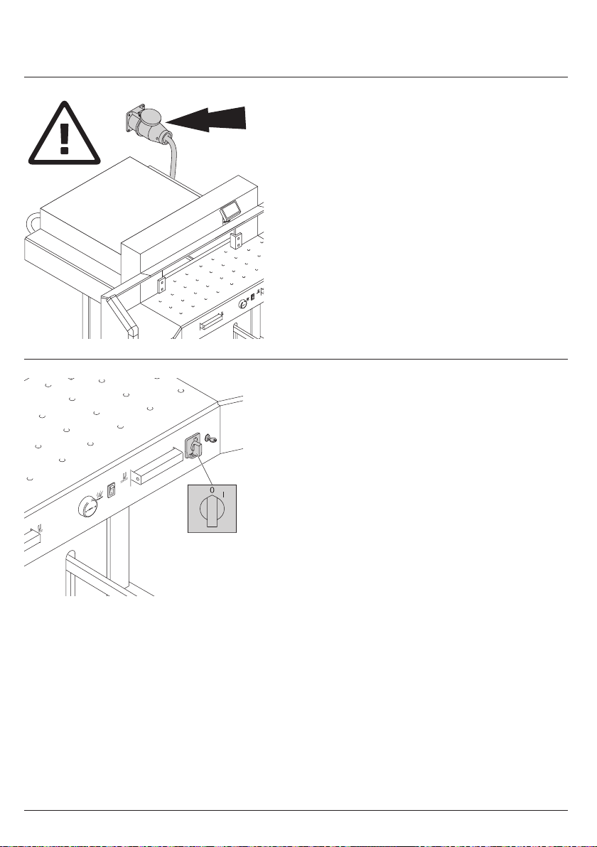
Protect mains cable against heat, oil and
sharp edges!
Standard machines are factory-set as follows:
• Power supply:
400 V, 3P+N+PE
220 V, 3P+PE
• Frequency 50 / 60 Hz.
Machine does not function
• Is the machine Eswitched on?
• Is the key-switch Don.
• Is the green overload switch apressed?
• Is the black overload switch bpressed?
• Check on-site fuse.
If the machine still does not function then the
rotation must be reversed.
The machine is wired according to the
IEC standards. We recommend that alterations
to the rotary direction be made in the socket.
It is also possible to make alterations in the
plug by exchanging "L1" and "L2".
Danger!
Incorrect exchanging of the connections
will endanger the operator.
This work must be carried out by an
electrician.
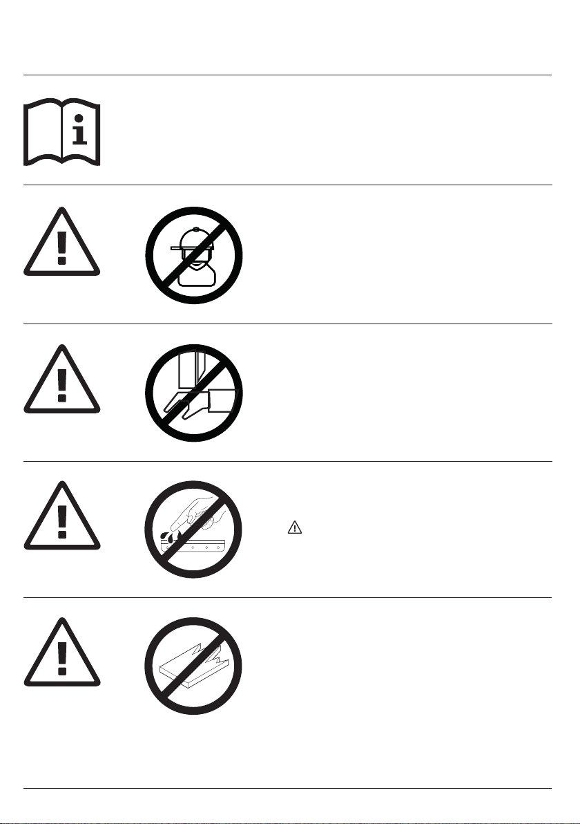
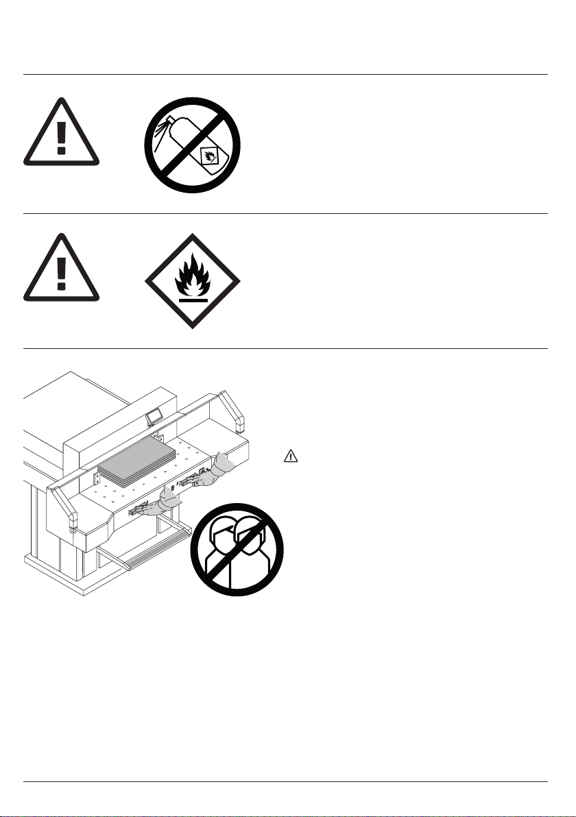
Safety precautions