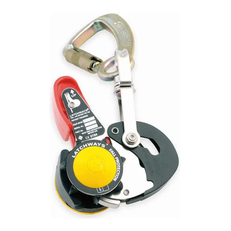
Latchways ManSafe SRL User manual

ManSafe®SRL
User instructions
Mode d’emploi
Bedienungsanleitung
Gebruiksaanwijzing
Brugervejledning
Bruksanvisning
Användarinstruktioner
Instrucciones de usuario
Istruzioni per l’uso
Instruções para o usuário
User instructions
62004-98US Issue 3
IMPORTANT DOCUMENT—DO NOT THROW AWAY

2
EN
English 3
FR
French European 13
DE
German European 24
NL
Dutch 34
DK
Denmark 44
NO
Norway 53
SW
Sweden 63
ES
Spanish 73
IT
Italian 84
BR
Brazilian Portuguese 94
© Copyright 2013 Latchways plc. 62004-98US – Issue 3.

3
No part of this document may be reproduced or transmitted in any form or
by any means, without prior permission in writing from Latchways plc.
The user must read, understand and follow this instruction manual before using this
equipment. This manual must be kept in a safe place for future reference along with the
inspection records and should be used as part of an employee training program.
It is essential for the safety of the user that if the SRL is resold outside the original
country of destination the reseller shall provide instructions for use, maintenance,
periodic examination and for repair in the language of the country in which the device
will be used.
Contact Latchways if you have any concerns regarding the use, maintenance, applications or
operation of this device.
EN
ManSafe
®
SRL User Instructions
EN
Certificate of Conformity
This product conforms to all regional requirements and specifications for this product type which
are: EN 360:2002, ANSI Z359.14 – 2012 and CSA Z259.2.2-98.
Place lock test sticker here
EN 360:2002 ANSI Z359.14 – 2012 CSA Z259.2.2-98
Serial Number Date of
Manufacture
Position in Company Signed
dd / mm / yy

4
When tested in accordance with EN360 Maximum arrest force 6 kN (1350 lbs).
Maximum arrest distance 2 m (78.74”).
When tested in accordance with ANSI
Z359.14 – 2012 Maximum arrest force 6 kN (1350 lbs).
Maximum arrest distance 1.37 m (54”).
Average arrest force 4 kN (900 lbs).
When tested in accordance with CSA
Z259.2.2-98 (reaffirmed 2009) Maximum arrest force 6 kN (1350 lbs).
Maximum arrest distance 1.4 m (55”).
Manufactured by Attestation of Conformity Production Control Phase
Latchways plc
Hopton Park
Devizes
Wiltshire
SN10 2JP
United Kingdom
Tel: +44 (0) 1380 732700
Fax: +44 (0) 1380 732701
www.latchways.com
Notified Body number 0321
SATRA Technology Centre Ltd
Wyndham Way
Telford Way
Kettering
Northamptonshire
NN16 8SD
United Kingdom
Tel: +44 (0)1536 410000
Notified Body number 0194
INSPEC Certification
Services
56 Leslie Hough Way
Greater Manchester
M6 6AJ
United Kingdom
Tel: +44 (0)1617 370699
Due to constant development, the products packed may differ in detail from the images in this manual.
EN
Certificate of Conformity
Webbing (polyester) Cable (Ø5 mm)
2m (7ft) 2.5m (8ft)
3.6m (12ft) 4.5m (15ft)
7m (23ft) Other
7m (23ft) 9m (30ft) 10m (33ft)
12m (40ft) 15m (50ft) 25m (85ft)
40m (130ft) Other
S/S
Galv
NOTE: Webbing Size 2 m (7ft) and 2.5 m (8ft) SRL’s use 20 mm x 1.3 mm webbing. 3.6 m (12ft) and 4.5 m (15ft) SRL’s use
20 mm x 2.0 mm webbing. 7 m (23ft) SRL’s use 25 mm x 2.0 mm webbing.

5
No part of this document may be reproduced or transmitted in any form or
by any means, without prior permission in writing from Latchways plc.
EN
Warranty details
Thank you for purchasing this Latchways product from its Self Retractable Lifeline (SRL) range of
safety products. Should you need to use our warranty service on this product, we refer you to the full
terms and conditions at http://warranty.latchways.com.
Standard Conditions
Latchways wants this product to be in good working order during the warranty period. In the event that
the product is found to be defective within the warranty period, a repair service will be provided free of
charge at the authorised service centre in the country in which the product was purchased.
This Latchways free of charge service may only be obtained against a validly entered warranty
registration on the Latchways website http://warranty.latchways.com, detailing (a) the purchasers
name and contact details, (b) the retailer’s name and address, (c) the model name and serial number
and (d) the date of purchase of the product. Latchways reserves the right to refuse warranty service
if this information is not complete or has been removed or changed after the original purchase
of the product by the consumer from the retailer. Latchways further reserves the right to replace
the defective product with another equivalent product which has the same or similar quality to the
defective product, instead of repairing the defective product.
1. Warranty Period
This warranty is valid for five years for the Sealed SRL and two years for all other products
from the SRL range, from the date of purchase by the consumer, as evidenced by the
aforementioned documents.
2. To Obtain Warranty Service
Warranty service is available in the authorised Latchways service centres or by returning the defective
product to Latchways, marked for the attention of the Service Manager at Hopton Park, Devizes,
Wiltshire, SN10 2JP, UK.
Register your product at http://warranty.latchways.com as specified in the standard terms.
EN
Inspection Log
To be completed by a competent inspection entity (see glossary of terms page 12) and retained
by the site safety officer or the user.
Date of first use (see glossary of terms page 12) dd / mm / yy
Date Inspected by (Block Capitals) Signature Inspection Completed/Comments Date of Next Inspection
dd / mm / yy
✓
dd / mm / yy
ASee completed example below for guidance (page 108).
02 05 13 02 05 14PASSEDPAUL HIGGINS
✓
1 2 3 4 5

6
CRear Label (see page 104)
DWebbing Shock Absorber Label (see page 104)
EDate of Next Service Label (see page 104)
BFront Label (see page 104)
GRear Label (see page 105)
DWebbing Shock Absorber Label (see page 104)
EDate of Next Service Label (see page 104)
FFront Label (see page 105)
EN
2m Webbing SRL Product Markings
1Manufacturer
2Date of Manufacture
3Read Instructions
4Part Number
5Specification
6Product Description
7ATEX Approval
8Serial Number
9Notified Body
10 Standard
11 Date of Next Service
EN
Webbing SRL Product Markings
1Date of Manufacture
2Serial Number
3Manufacturer
4Part Number
5Standard
6Specification
7Product Description
8Notified Body
9ATEX Approval
10 Read Instructions
11 Date of Next Service

7
No part of this document may be reproduced or transmitted in any form or
by any means, without prior permission in writing from Latchways plc.
IRear Label (see page 106)
EDate of Next Service Label (see page 104)
HFront Label (see page 106)
EDate of Next Service Label (see page 104)
JFront Label (see page 107)
EN
Cable SRL Product Markings
1Manufacturer
2Date of Manufacture
3Serial Number
4Read Instructions
5ATEX Approval
(cable SRL only)
6Specification
7Product Description
8Part Number
9Notified Body
10 Standard
11 Date of Next Service
EN
Sealed SRL Product Markings
1Manufacturer
2ATEX Approval
(cable SRL only)
3Product Description
4Read Instructions
5Notified Body
6Date of Manufacture
7Part Number
8Standard
9Specification
10 Serial Number
11 Date of Next Service

8
EN
ManSafe
®
SRL User Instructions
Latchways SRLs are designed to be the easiest to operate and maintain, requiring minimal maintenance and the simplest visual
checks to ensure they are safe to use. The simplicity of the procedures required are summarised in the three stages highlighted in
the easy to follow flowchart which allows the user to quickly ascertain the current mechanical status of the product and suitability
for the work about to be undertaken.
Operation and use: Attach the SRL overhead to a suitable anchorage or anchorage connector then follow the operational process in the flow chart
below
(Exception: Either end of the 2 m (7 ft) and 2.5 m (8 ft) Webbing SRLs may be attached to the designated fall arrest attachment point of a
full body harness–this only applies to the 2 m (7 ft) and 2.5 m (8 ft) webbing SRLs)
.
1. Before use inspection by competent user*
2. Periodic inspection by competent inspection entity*
3. Repair and recertification by competent repair entity*
Pull gently on
lifeline—listen for
audible clicking.
2
Labels 4
General
unit
inspection
5
Locking
mechanism
6
Lifeline
(cable/
webbing)
inspection
Pull sharply on
lifeline—check
device locks.
Check load
indicator is not
deployed.
SAFE TO
USE
RETURN TO
SERVICE
Operate connector:
Check connect operation.
Check for signs of damage/
deterioration.
Email: SRLrepair@latchways.com
PASS
PASS PASS PASS PASS PASS PASS
PASS
FAIL
FAIL
PASS PASS
1
Load
indicators
3
Connectors

9
No part of this document may be reproduced or transmitted in any form or
by any means, without prior permission in writing from Latchways plc.
Key for inspection by competent inspection entity*
> 10 KN< 10 KN
“tic, tic”
1 Load indicators
Cable SRL’s load indicator is a constant force energy sorbing coil designed to
deploy in the event of a fall which will result in it protruding from the top of the SRL.
If any red colour is visible on the absorber coil then loading has occurred.
Webbing SRL’s load indicator is incorporated into the webbing lifeline. Deployment
is indicated by a red warning symbol being displayed on the lifeline.
Sealed and standard cable SRL’s load indicator is incorporated into a swivel hook
designed to deploy in the event of a fall. If any red colour is visible around the swivel
area of the hook then loading has occurred.
2 Labels Inspect to ensure all are present and fully legible.
3 Connectors Inspect for working condition and signs of damage or corrosion.
4General unit
inspection
Visually inspect for signs of corrosion, damage or distortion. Ensure all fastenings are present and secure.
The swivel eye on webbing models must turn freely, the spiral pin must be present and securely fixed, and
the fastening bolt must be flush with eyelet surface.
5 Locking mechanism
Fully extract the lifeline and as it retracts it must do so without hesitation (no slack line should occur).
During extraction and retraction ensure that a clicking sound (created by Latchways patented Full Contact®
mechanism) can be heard and that when pulled sharply it locks up. If there is no clicking sound or if the
device does not lock, DO NOT USE.
6 Lifeline inspection If the lifeline has any cuts, broken strands, kinks, bird-caging, welding spatter, burns, abraded areas or
shows signs of excessive soiling, corrosion or UV degradation it must be replaced.
> 10 KN< 10 KN
“tic, tic”
“tic, tic”
> 10 KN< 10 KN
*Full definition of these terms is available on page 12.

10
EN
ManSafe
®
SRL User Instructions
PRODUCT CAPABILITY
Maximum user
weight
Maximum user weight (including tools) is 140 kg (310 lbs) for
webbing SRLs and 180 kg (400 lbs) for cable SRLs.
Temperature range
suitability
Latchways SRLs can be used in temperatures ranging from
-40°C (-40°F) to 54°C (130°F).
Vertical use only Latchways SRLs should be positioned as vertically as possible above
the position of the user to minimise the risk of striking an object/
obstacle in the event of a pendulum fall and used at an angle that is
no more than 30° to the vertical.
ATEX rating All Latchways SRL’s are suitable for use in areas in which explosive
atmospheres caused by mixtures of air and gases, vapours or mists
or by air/dusts mixtures are likely to occur, as per EN 13463-1:2001
equipment group II, category 2 ( II 2 G c IIC T6).
Secondary Tether
Lines
If required, Latchways Cable SRLs can be supplied with a
secondary tether line facility—for more details contact Latchways
via www.latchways.com.
Personnel requirements: Latchways SRLs should only be used by a person who is trained and
competent (see glossary of terms page 12) in its safe use. Fitness and age significantly affect a
person’s ability to safely withstand fall arrest loads. Only people who are physically and mentally fit
and healthy, not under the influence of drugs or alcohol are permitted to use this equipment. If you
are uncertain about your ability, consult your doctor. Latchways SRLs must not be used by pregnant
women or minors.
Intended purpose: The Self Retracting Lifeline (SRL) in accordance with EN/ANSI/CSA
standards is intended to be used as a connecting element within a personal fall arrest system.
It must be used vertically in situations where user mobility is required and fall protection is needed—
inspection, general construction and maintenance work etc.
Product limitations: Latchways SRLs shall not be used outside their limitations, or any purpose
other than that for which they are intended. Repairs are to be conducted by a competent repair
entity. Do not attempt to modify or repair the equipment. It is critical for your safety that these
instructions are followed and the equipment is not misused.
1. The SRLs are for a single user only, only one person can be connected at any time.
2. The SRLs must be protected from fire, acids, caustic solutions, welding flames, sparks or similar.
3. The SRL must not be used if there is any risk of the SRL contacting high voltage power lines.
This warning also applies to webbing type devices as moisture can be absorbed by the lifeline
providing a path for electrical current.
4. When using the SRL in a caged ladder striking the cage may occur during a fall. The use of
climbing helmets is recommended to reduce the risk of injury.
System requirements: A fall arrest system comprises of a structural anchor point, full body
harness, connector (karabiner/hook) and SRL. Ensure all elements in the system are used only
as specified by the manufacturer. It is essential for safety that the anchor device and anchor point
should always be positioned, and work carried out in such a way, as to minimise both the potential
for a fall and potential fall distance.

11
No part of this document may be reproduced or transmitted in any form or
by any means, without prior permission in writing from Latchways plc.
NOTE: Selection of the anchor point position must take in to account any risks posed by moving
machinery and pendulum falls. To ensure positive locking of the SRL a clear, unobstructed fall
path is necessary. Do not use the SRL when working on such materials as sand or grain, as this
may not allow sufficient speed to cause the SRL to lock in the event of a fall. It is essential for
safety to verify the free space required beneath the user at the workplace before each occasion
of use, so that, in the event of a fall there will be no collision with the ground or other obstacle
in the fall path. If more than one personal fall arrest system is attached to the same supporting
structure then the former strength requirement has to be multiplied by the number of personal fall
arrest systems attached to the supporting structure. A minimum of 10 ft (3 m) from the working
level to the nearest obstruction, lower level or ground underneath a hazard should be maintained.
WARNING! Incompatible components can lead to connectors accidentally disengaging.
Always ensure all connectors are correctly engaged and locked.
1. Connectors shall conform to EN 362:2004, ANSI Z359.12-2009 and/or CSA Z259.12-11
and be self-closing and self-locking.
2. A full body harness conforming to EN 361:2002, ANSI Z359.1-2007 and/or CSA Z259.10-12
shall be worn when using the Latchways SRL.
3. An emergency written rescue plan must be in place, to be implemented in the event of a fall.
Cleaning, Storage and Transportation: Outside the defined inspection flowchart on page 8,
the SRL may be required to be temporarily removed from service e.g. for cleaning. If required,
clean the SRL exterior, lifeline and labels (to maintain legibility) with warm water (40ºC, 100°F)
and non biological detergent then rinse. An excessive build-up of dirt or paint etc. on the lifeline
may compromise the retraction. If the SRL becomes wet, either from being in use or from cleaning,
position the SRL such that any excess water can drain out and leave to dry naturally away from
direct heat. SRL’s scheduled for maintenance shall be tagged DO NOT USE and withdrawn from
service. The full body harness and any other system components should be cleaned and stored
according to manufacturer’s instructions. Store the SRL in a cool, dry, clean environment.
Ensure SRL is away from dust, oil and direct sunlight. Inspect the SRL after long periods of
storage. During transportation the device must be protected to prevent damage or contamination.
ANCHORAGE STRENGTH
EU The anchorage structure shall be able to sustain a minimum load of
12 kN. Refer to EN 795:2012 or CEN TS16415.
US The anchorage structure shall be able to sustain a minimum certified
load of 3600 lbs (16 kN) or 5000 lbs (22.2 kN) in the absence of
certification. Refer to ANSI Z359.1-2007.
Canada The anchorage structure shall be able to sustain a minimum load of
5060 lbs (22.5 kN). Refer to CSA Z259.15
Note: If more than one personal fall arrest system is attached to the same supporting structure
then the former strength requirement has to be multiplied by the number of personal fall arrest
systems attached to the supporting structure.

12
When not in use: Do not allow the lifeline to be fully extracted for long periods of time as this may
cause weakening of the retraction spring. Do not let go of the lifeline as it will retract at high speed
potentially damaging internal parts. If the SRL is positioned high above the users head, the use of
a tag line is acceptable to allow the SRL to fully retract and yet enable retrieval of the connector.
Unless specified, it is recommended for tag lines to be removed from the device before use.
The ‘do nots’:
Do not use an additional lanyard or similar component to lengthen the line.
Do not allow the lifeline to pass through legs or under arms.
Do not use this product for ground level attachments or cable systems.
Do not use over an edge.
Do not allow the lifeline to be in contact with or rub against sharp edges.
Do not allow the lifeline to come into contact with moving machinery.
Webbing lifelines and UV rays: The lifeline within webbing models when subjected to prolonged
periods outside may deteriorate. UV rays can cause the colour of the lifeline to fade and may
reduce its strength. If severe discolouration is visible the lifeline must be replaced by a competent
repair entity. The life of the product can be affected by environmental conditions. The service life of
SRL webbing has been evaluated to be up to 10 years. However, the following factors such as
(but not limited to): environmental conditions (e.g. contact with chemicals, exposure to temperatures
>60°C (>140°F)), incorrect storage, frequency of use, may reduce service life. If the webbing fails
inspection, it must be replaced by a competent repair entity.
GLOSSARY OF KEY TERMS
Competent user: This is a person that has been trained in the safe use and operation of the
Latchways SRL and is also trained to conduct the before use inspection.
Competent inspection entity: This is a person(s)/organisation, other than the competent user,
trained and authorised by Latchways to conduct the periodic examination/inspection.
Competent repair entity: This is a person(s)/organisation, other than the competent user,
trained and authorised by Latchways to conduct repairs/replacement of damaged/worn parts.
With appropriate additional training the inspection entity can also be a repair entity.
Date of first use: Is defined as the day the unit is removed from the packaging and exposed to
the elements.
Repair: This requires the authorised repair entity to replace damaged or worn parts. Should
the before use inspection or periodic inspection checks identify defects such as worn webbing,
damaged cable, deployed energy absorber etc.
Recertification: This requires the competent inspection entity to confirm in writing details of the
repair, date of repair and that the SRL can be returned to service. Repair and recertification shall
only be carried by a competent repair entity. SRL’s scheduled for repair shall be tagged DO NOT
USE and withdrawn from service.
Periodic inspection covers the checks that should be completed by an authorised inspection
entity other than the user at least every 12 months. Local legislation or environmental conditions
(corrosive or chemical environments) may dictate more frequent recertification intervals.
EN
ManSafe
®
SRL User Instructions

13
Aucune partie de ce document ne peut être reproduite ou
transmise sous quelque forme ou par quelque procédé que ce
soit sans l’autorisation préalable écrite de Latchways plc.
L’utilisateur doit lire, comprendre et respecter ce mode d’emploi avant d’utiliser
l’équipement. Ce mode d’emploi doit être conservé dans un endroit sûr pour référence
future, conjointement aux fiches d’inspection, et il doit être utilisé dans le cadre d’un
programme de formation des employés. Pour la sécurité de l’utilisateur, si la LAR est
revendue en dehors du pays d’origine, il est essentiel que le revendeur fournisse les
instructions d’utilisation, d’entretien, de vérification périodique et de réparation dans la
langue du pays dans lequel le dispositif sera utilisé.
Contactez Latchways si vous avez une question concernant l’utilisation, l’entretien, les applications
ou le fonctionnement de ce dispositif.
FR
Mode d’emploi de la LAR ManSafe
®
FR
Certificat de conformité
Ce produit est conforme à toutes les exigences et spécifications régionales pour ce type de
produit, à savoir : EN 360:2002, ANSI Z359.14 – 2012 et CSA Z259.2.2-98.
Placez l’autocollant d’essai de verrouillage ici
Numéro de série Date de fabrication Poste au sein de
la société
Signature
dd / mm / yy
EN 360:2002 ANSI Z359.14 – 2012 CSA Z259.2.2-98

14 © Copyright 2012 Latchways plc. 62004-98US – Issue 3.
Quand testée conformément à EN360 Force d’arrêt maximale 6 kN.
Distance d’arrêt maximale 2 m.
Quand testée conformément à
ANSI Z359.14 – 2012 Force d’arrêt maximale 6 kN.
Distance d’arrêt maximale 1,37 m.
Force d’arrêt moyenne 4 kN.
Quand testée conformément à
CSA Z259.2.2-98 (confirmée en 2009) Force d’arrêt maximale 6 kN.
Distance d’arrêt maximale 1,4 m.
Fabriqué par Attestation de conformité Phase de contrôle
de la production
Latchways plc
Hopton Park
Devizes
Wiltshire
SN10 2JP
United Kingdom
Tel: +44 (0) 1380 732700
Fax: +44 (0) 1380 732701
www.latchways.com
Notified Body number 0321
SATRA Technology Centre Ltd
Wyndham Way
Telford Way
Kettering
Northamptonshire
NN16 8SD
United Kingdom
Tel: +44 (0)1536 410000
Notified Body number 0194
INSPEC Certification
Services
56 Leslie Hough Way
Greater Manchester
M6 6AJ
United Kingdom
Tel: +44 (0)1617 370699
En raison d’un développement constant, certains détails des produits conditionnés peuvent être différents des images
présentées dans ce manuel.
FR
Certificat de conformité
Sangle (polyester) Câble (Ø5 mm)
2m (7ft) 2.5m (8ft)
3.6m (12ft) 4.5m (15ft)
7m (23ft) Other
7m (23ft) 9m (30ft) 10m (33ft)
12m (40ft) 15m (50ft) 25m (85ft)
40m (130ft) Other
S/S
Galv
NOTE : Longueur de la sangle : les LAR de 2 m et 2,5 m disposent d’une sangle de 20 mm x 1,3 mm. Les LAR de 3,6 m
et 4,5 m disposent d’une sangle de 20 mm x 2,0 mm. La LAR de 7 m dispose d’une sangle de 25 mm x 2,0 mm.

15
Aucune partie de ce document ne peut être reproduite ou
transmise sous quelque forme ou par quelque procédé que ce
soit sans l’autorisation préalable écrite de Latchways plc.
FR
Informations sur la garantie
Nous vous remercions d’avoir acheté ce produit Latchways de la gamme de sécurité des longes
auto-rétractables (LAR). Si vous avez besoin de faire appel à notre service de garantie pour ce
produit, veuillez consulter les conditions complètes sur http://warranty.latchways.com.
Conditions générales
Latchways garantit le bon fonctionnement de ce produit pendant la période de garantie. Si ce produit
s’avère défectueux pendant la période de garantie, un service de réparation sera fourni gratuitement
au centre de service agréé, dans le pays dans lequel le produit a été acheté.
Ce service gratuit Latchways est disponible uniquement si l’enregistrement de la garantie a été
correctement saisi et validé sur le site internet de Latchways http://warranty.latchways.com, en
précisant (a) le nom et les coordonnées de l’acheteur, (b) le nom et les coordonnées du revendeur,
(c) le nom du modèle et le numéro de série, et (d) la date d’achat du produit. Latchways se réserve
le droit de refuser ce service de garantie si ces informations sont incomplètes, si elles ont été
supprimées ou modifiées après l’achat initial du produit par le consommateur chez le revendeur.
De plus, Latchways se réserve le droit de remplacer le produit défectueux par un autre produit
équivalent, de qualité identique ou similaire au produit défectueux, au lieu de le réparer.
1. Durée de la garantie
Cette garantie est valable pendant cinq ans pour la LAR étanche et pendant deux ans pour tous
les autres produits de la gamme LAR, à compter de la date d’achat par le consommateur, tel que
mentionné dans les documents précités.
2. Bénéficier du service de garantie
Le service de garantie est disponible dans les centres de service agréés de Latchways ou en
retournant le produit défectueux à Latchways, adressé à l’attention du responsable du service
d’entretien, à Hopton Park, Devizes, Wiltshire, SN10 2JP, Royaume-Uni.
Veuillez enregistrer votre produit sur http://warranty.latchways.com, comme prévu dans
les conditions générales.
FR
Cahier d’inspection
À remplir par une entité d’inspection compétente (voir glossaire des termes à la page 22) et à
conserver par le responsable de la sécurité du site ou par l’utilisateur.
Date de première utilisation (voir glossaire des termes à la page 22) dd / mm / yy
Date Inspecté par
(en majuscules)
Signature Inspection réalisée /
commentaires
Date de la prochaine
inspection
dd / mm / yy
✓
dd / mm / yy
APour plus de consignes, veuillez consulter l’exemple présenté ci-dessous (page 108).
02 05 13 02 05 14CONFORMEPAUL HIGGINS
✓
1 2 3 4 5

16
FR
Marquages des produits LAR à sangle de 2 m
CÉtiquette de dos (voir page 104)
DÉtiquette Amortisseur de la sangle (voir page 104)
EÉtiquette Date du prochain entretien (voir page 104)
BÉtiquette de face (voir page 104)
GÉtiquette de dos (voir page 105)
DÉtiquette Amortisseur de la sangle (voir page 104)
EÉtiquette Date du prochain entretien (voir page 104)
FÉtiquette de face (voir page 105)
1Fabricant
2Date de fabrication
3Lire les instructions
4Référence
5Spécification
6Description du produit
7Certification ATEX
8Numéro de série
9Organisme notifié
10 Norme
11 Date du prochain entretien
FR
Marquages des produits LAR à sangle
1Date de fabrication
2Numéro de série
3Fabricant
4Référence
5Norme
6Spécification
7Description du produit
8Organisme notifié
9Certification ATEX
10 Lire les instructions
11 Date du prochain entretien

17
Aucune partie de ce document ne peut être reproduite ou
transmise sous quelque forme ou par quelque procédé que ce
soit sans l’autorisation préalable écrite de Latchways plc.
FR
Marquages des produits LAR à câble
IÉtiquette de dos (voir page 106)
EÉtiquette Date du prochain entretien (voir page 104)
HÉtiquette de face (voir page 106)
EÉtiquette Date du prochain entretien (voir page 104)
JÉtiquette de face (voir page 107)
1Fabricant
2Date de fabrication
3Numéro de série
4Lire les instructions
5Certification ATEX
(LAR à câble uniquement)
6Spécification
7Description du produit
8Référence
9Organisme notifié
10 Norme
11 Date du prochain entretien
EN
Sealed SRL Product Markings
1Fabricant
2Certification ATEX
(LAR à câble uniquement)
3Description du produit
4Lire les instructions
5Organisme notifié
6Date de fabrication
7Référence
8Norme
9Spécification
10 Numéro de série
11 Date du prochain entretien

18
FR
Mode d’emploi de la LAR ManSafe
®
Les LAR de Latchways sont conçues pour être extrêmement faciles à utiliser et à entretenir du fait qu’elles ne nécessitent
qu’un entretien minimal et que des vérifications visuelles très simples permettent de s’assurer de leur utilisation sécurisée. Ces
procédures simples mais obligatoires sont résumées en trois étapes dans un diagramme facile à suivre, qui permet à l’utilisateur de
vérifier rapidement l’état mécanique actuel du produit et que le produit est adapté au travail à effectuer.
Fonctionnement et utilisation : fixez la LAR en hauteur en l’attachant à un point d’ancrage ou un connecteur d’ancrage approprié. Ensuite, suivez
le processus fonctionnel décrit dans le diagramme ci-dessous.
(Exception : l’une des extrémités des LAR à sangle de 2 m et de 2,5 m peut être
fixée au point d’attache antichute désigné d’un harnais complet ; ceci ne s’applique qu’aux LAR à sangle de 2 m et de 2,5 m).
1. Inspection avant l’utilisation par un utilisateur compétent*
2. Inspection périodique par une entité d’inspection compétente*
3. Réparation et nouvelle certification par une entité de réparation compétente*
Tirez doucement sur
la longe ; écoutez
pour entendre un
déclic sonore.
2
Étiquettes 4
Inspection
générale de
l’unité
5
Mécanisme
de
verrouillage
6
Inspection
de la longe
(câble /
sangle)
Tirez d’un coup sec
sur la longe ; vérifiez
que le dispositif
se bloque.
Assurez-vous
que l’indicateur
de charge n’est
pas déployé.
UTILISATION
SÉCURISÉE
REMISE EN
SERVICE
Faites fonctionner le connecteur :
Vérifiez le fonctionnement du
connecteur. Vérifiez qu’il n’y a aucun
signe de dommages / détérioration.
E-mail: SRLrepair@latchways.com
CONFORME
CONFORME CONFORME CONFORME CONFORME CONFORME CONFORME
CONFORME
NON CONFORME
NON CONFORME
CONFORME CONFORME
1
Indicateurs
de charge
3
Connecteurs

19
Aucune partie de ce document ne peut être reproduite ou
transmise sous quelque forme ou par quelque procédé que ce
soit sans l’autorisation préalable écrite de Latchways plc.
Légende pour l’inspection par une entité d’inspection compétente*
> 10 KN< 10 KN
“tic, tic”
1
Indicateurs
de charge
L’indicateur de charge de la LAR à câble est une bobine d’absorption d’énergie à force constante, conçue pour
se déployer en cas de chute, l’indicateur ressortant par le sommet de la LAR.
Si une couleur rouge apparaît sur la bobine de l’absorbeur, alors une charge s’est produite.
L’indicateur de charge de la LAR à sangle est intégré dans la longe. Le déploiement est indiqué par un
symbole d’avertissement rouge présent sur la longe.
L’indicateur de charge des LAR étanches et à câble standard est intégré dans un crochet pivotant, conçu
pour se déployer en cas de chute. Si une couleur rouge apparaît autour de la section pivotante du crochet, alors
une charge s’est produite.
2
Étiquettes
Vérifiez qu’elles sont toutes présentes et parfaitement lisibles.
3
Connecteurs
Inspectez le fonctionnement et les signes de dommages ou de corrosion.
4
Inspection
générale de
l’unité
Vérifiez visuellement les signes de corrosion, de dommages ou de déformation. Assurez-vous que toutes les pièces de fixation sont
présentes et serrées. Sur les modèles à sangle, l’émerillon doit tourner librement, la goupille à section spiralée doit être présente et
solidement fixée, et le boulon de fixation doit être aligné avec la surface de l’œillet.
5
Mécanisme
de
verrouillage
Étirez totalement la longe. Lorsqu’elle se rétracte, elle doit pouvoir le faire immédiatement (la longe ne doit pas être détendue). Pendant
l’extraction et la rétraction, vérifiez que vous entendez un déclic sonore (créé par le mécanisme breveté Full Contact®de Latchways) et
vérifiez que le dispositif se bloque quand vous tirez d’un coup sec. En l’absence d’un déclic sonore ou si le dispositif ne se bloque pas,
N’UTILISEZ PAS LA LAR.
6
Inspection de
la longe
Si la longe présente des entailles, des fils brisés, des enroulements, une déformation en lanterne, des projections de soudure, des brûlures,
des zones usées ou des traces d’encrassement excessif, de corrosion ou de dégradation par les UV, il est nécessaire de la remplacer.
> 10 KN< 10 KN
“tic, tic”
“tic, tic”
> 10 KN< 10 KN
*Une définition complète de ces termes est disponible à la page 22.

20
FR
Mode d’emploi de la LAR ManSafe
®
CAPACITÉ DU PRODUIT
Poids maximal de
l’utilisateur
Le poids maximal de l’utilisateur (avec outils) est de 140 kg pour les LAR à sangle
et de 180 kg pour les LAR à câble.
Plage de
température
appropriée
Les LAR de Latchways peuvent être utilisées de -40°C à +54°C.
Utilisation
verticale
uniquement
Les LAR de Latchways doivent être placées autant que possible à la verticale,
au-dessus de la position de l’utilisateur, pour minimiser le risque de collision avec
un objet / obstacle en cas de chute pendulaire, et être utilisées à un angle de 30°
maximum par rapport au plan vertical.
Certification
ATEX
Conformément à la norme EN 13463-1:2001, groupe d’appareils n°II, catégorie 2
(II 2 G c IIC T6), les LAR de Latchways peuvent être utilisées dans des zones où
des atmosphères explosives sont susceptibles d’être provoquées par des mélanges
d’air et de gaz, de vapeurs ou de brouillards ou par des mélanges air / poussières.
Câbles d’attache
secondaires
Si nécessaire, les LAR à câble de Latchways peuvent être fournies avec un
câble d’attache secondaire. Pour de plus amples informations, veuillez contacter
Latchways par le biais du site www.latchways.com.
Exigences relatives au personnel : les LAR de Latchways doivent être utilisées uniquement
par une personne compétente et formée (voir glossaire des termes à la page 22) à leur utilisation
sécurisée. La santé et l’âge ont des répercussions majeures sur la capacité d’une personne
à supporter en toute sécurité les charges entrant en jeu lors de l’arrêt d’une chute. Seules les
personnes qui sont en bonne santé physique et mentale, et n’étant pas sous l’emprise de drogues,
de médicaments ou de l’alcool, sont autorisées à utiliser cet équipement. Si vous n’êtes pas sûr(e) de
votre état, veuillez consulter un médecin. Les LAR de Latchways ne doivent pas être utilisées par les
femmes enceintes ou les personnes mineures.
Utilisation prévue : conformément aux normes EN/ANSI/CSA, la longe auto-rétractable (LAR)
est destinée à être utilisée en tant qu’élément de raccordement à un système antichute individuel.
Elle doit être utilisée verticalement dans des situations requérant à la fois la mobilité de l’utilisateur et
une protection antichute : inspection, construction générale, travaux de maintenance etc.
Limites du produit : les LAR de Latchways ne doivent pas être utilisées au-delà de leurs limites,
ou dans tout autre but que celui auquel elles sont destinées. Les réparations doivent être réalisées
par une entité de réparation compétente. N’essayez pas de modifier ou de réparer cet équipement.
Pour votre sécurité, il est primordial de respecter ces instructions et de ne pas utiliser l’équipement
de manière incorrecte.
1. Les LAR sont destinées à un seul utilisateur. Une seule et unique personne peut être
attachée au dispositif à tout instant.
2. Les LAR doivent être conservées à l’abri du feu, des acides, des solutions caustiques, des
flammes de soudage, des étincelles ou similaires.
3. The SRL must not be used if there is any risk of the SRL contacting high voltage power lines.
This warning also applies to webbing type devices as moisture can be absorbed by the lifeline
providing a path for electrical current.
4. Lorsque la LAR est utilisée dans une échelle à crinoline, l’utilisateur peut heurter la crinoline en cas
de chute. Il est conseillé de porter un casque d’escalade pour limiter les risques de blessures.
Other manuals for ManSafe SRL
2
Table of contents
Languages:
Other Latchways Security Sensor manuals
Popular Security Sensor manuals by other brands

Elko
Elko iNels Air AirWD-101 Series manual

DMP Electronics
DMP Electronics DEL AOP PRO 50 INSTALLATION INSTRUCTIONS & PRODUCT MANUAL

Iriss
Iriss Sonus PD operating manual

System Sensor
System Sensor SpectrAlert CH24MC Series Installation and maintenance instructions

AVE
AVE AF970R manual

ABB
ABB Orion1 Base Excerpts From the Instruction Manual

Pasesa
Pasesa AVE-2000 Pro Instructions for use

LEAKSHOOTER
LEAKSHOOTER LKS1000 user manual

Waygate Technologies
Waygate Technologies Krautkramer USM 10 operating manual

Honeywell
Honeywell 2MLF-RD4A user guide

IXOM
IXOM CHLORGUARD user manual

Fire Sentry
Fire Sentry SS4-AS Installation guide and operating manual