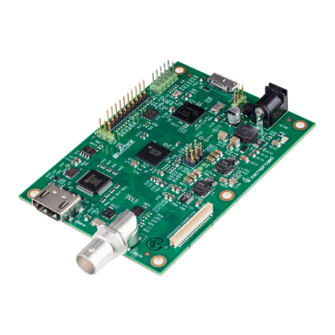
Lattice Crosslink-NX User manual


Crosslink-NX VIP Sensor
Input Board
Check the Kit Contents
The Crosslink-NX VIP Sensor Input Board kit contains the following items:
Crosslink-NX Sensor Input Board
IMX258 camera sensors (4 sensors, mounted on board)
Camera sensor support piece
USB Cable for Programming via PC (USB-A to Mini-B)
Quick Start Guide
This document provides a brief introduction to the Crosslink-NX VIP Sensor Input
Board. The board is pre-programmed to demonstrate the 4 to 1 Image Aggregation
Demo.
1
Crosslink-NX VIP Sensor Input Board
Quick Start Guide
This document provides a brief introduction to the Crosslink-NX VIP Sensor Input Board. The board is
pre-programmed to demonstrate the 4 to 1 Image Aggregation Demo.
LIFCL-40
Device (U16)
Parallel Config
Header (J6)
Mini USB
Programming (J2)
JTAG
Header (J1)
Camera Connector
(CN2)
HyperRAMs
(U60, U61)
Input Switches
(SW2)
PMOD Connector
(J34)
PMOD Connector
(J32)
PMOD Connector
(J33)
Output LEDs
(D25-D28)
Camera Bracket
Mounting Hole
Input
Pushbuttons
(SW5, SW6)
GSRN
Pushbutton (SW3)
PROGRAMN
Pushbutton (SW4)
FTDI Reset
Jumper (J3)
FTDI OSC
Jumper (JP2)
1. Check kit contents
The Crosslink-NX VIP Sensor Input Board kit contains the following items:
•Crosslink-NX Sensor Input Board
•IMX258 camera sensors (4 sensors, mounted on board)
•Camera sensor support piece
•USB Cable for Programming via PC (USB-A to Mini-B)
•Limited license with unique serial number for Lattice Radiant development software
(optional to use)

Crosslink-NX VIP Sensor
Input Board
Assembling the Demonstration Hardware
This board will only work when used as part of the Lattice Embedded Vision Develop-
ment Kit (EVDK). It is designed to be pin compatible with the Crosslink VIP Input
Bridge Board. Follow the steps below to prepare the hardware before applying power.
Remove Crosslink VIP Input Bridge Board from EVDK, replace with Crosslink-NX
VIP Sensor Input Board. Connectors J5 and J4 of the Crosslink-NX VIP Sensor
Input Board connect to J10 and J11 of the ECP5 VIP Processor Board.
Mount cameras to camera connectors (CN0, CN1, CN2, and CN4).
Mount camera sensor support piece and stick camera backs to piece.
The assembled hardware will look like the picture below:
2
•Quick Start Guide
2. Assembling the Demonstration Hardware
This board will only work when used as part of the Lattice Embedded Vision Development Kit
(EVDK). It is designed to be pin compatible with the Crosslink VIP Input Bridge Board. Follow
the steps below to prepare the hardware before applying power.
•Remove Crosslink VIP Input Bridge Board from EVDK, replace with Crosslink-NX VIP
Sensor Input Board. Connectors J5 and J4 of the Crosslink-NX VIP Sensor Input Board
connect to J10 and J11 of the ECP5 VIP Processor Board.
•Mount cameras to camera connectors (CN0, CN1, CN2, and CN4).
•Mount camera sensor support piece and stick camera backs to piece.
The assembled hardware will look like the picture below:
3. Run the Demonstration
•Apply power to the ECP5 VIP Processor Board using a 12V adapter.
•Connect jumpers to the Crosslink and ECP boards as follows:
CrossLink-NX Jumper Settings
Jumper
Pins to Connect
JP2
Open
J3
Open
—
All other headers should be kept open.
Run the Demonstration
Apply power to the ECP5 VIP Processor Board using a 12 V adapter.
Connect jumpers to the Crosslink and ECP boards as follows:
3
CrossLink Jumper Settings
Jumper Pins to Connect
J2 Open
J3 Open
--- All other headers
should be kept open
ECP5 Jumper Settings
Jumper Default
J3 1-2, 5-6
J5 1-2
J6 1-2
J7 2-3
J9 1-2
J50 1-2
J51 1-2
J52 2-3
J53 1-2
J55 2-3
--- All other headers
should be kept open

Additional Terms and Conditions Applicable to Lattice Programming and Development Hardware
Lattice device programmers, programming cables, socket adapters, and other hardware sold for use in conjunction with Lattice
software (“Programming Hardware”) and Lattice evaluation boards and development kits sold for use in conjunction with
evaluating Lattice products (“Development Hardware”) are designed and intended for use solely with semiconductor components
manufactured by Lattice Semiconductor Corporation. Programming and Development Hardware is warranted to meet Lattice
specications only for a period of ninety (90) days; in all other respects the terms and conditions of sale of Programming and
Development Hardware shall be Lattice’s standard terms and conditions set forth in Lattice’s Sales Order Acknowledgment.
Additionally, Lattice specications for Programming and Development Hardware limit their use to low-volume engineering
applications only, and not for volume production use. The warranty for Programming and Development Hardware will not apply to
any Programming or Development Hardware used in production, used with worn or improperly installed hardware, or used with
incompatible systems or components.
Technical Support
www.latticesemi.com
Copyright © 2019 Lattice Semiconductor Corporation. Lattice Semiconductor, L (stylized) Lattice Semiconductor Corp., Lattice
(design), Lattice Diamond, ECP5 and CrossLink are either registered trademarks or trademarks of Lattice Semiconductor
Corporation in the United States and/or other countries. Other product names used in this publication are for identication
purposes only and may be trademarks of their respective companies.
QS050 Rev. 2
December 2019
Crosslink-NX VIP Sensor
Input Board
Crosslink-NX VIP Sensor
Input Board
Connect HDMI cable between HDMI VIP Output Board and monitor.
The output of the 4 cameras will be observed on the monitor as a single video
stream.
SW3 on Crosslink-NX resets the pattern, SW5 changes camera view.
Done!
Congratulations! You have successfully demonstrated the 4 to 1 Image Aggregation
demo on the Crosslink-NX VIP Sensor Input Board. This demo is intended to
show basic functionality of the kit as shipped. This kit can be reprogrammed and/or
connected to additional hardware (available separately) to demonstrate a number
of bridging solutions. To learn more about these solutions and download full
documentation for this kit, including schematics for all the boards, visit the Lattice
website at: www.latticesemi.com/evdkit.
4
ECP5 Jumper Settings
Jumper
Default
J3
1-2, 5-6
J5
1-2
J6
1-2
J7
2-3
J9
1-2
J50
1-2
J51
1-2
J52
2-3
J53
1-2
J55
2-3
—
All other headers should be kept open.
•Connect HDMI cable between HDMI VIP Output Board and monitor.
•The output of the 4 cameras will be observed on the monitor as a single video
stream.
•SW3 on Crosslink-NX resets the pattern, SW5 changes camera view.
4. Done!
Congratulations! You have successfully demonstrated the 4 to 1 Image Aggregation demo on the
Crosslink-NX VIP Sensor Input Board. <REST OF THIS SECTION TEXT SAME AS BEFORE>
Development with the Lattice Crosslink-NX FPGA is supported by the Lattice Radiant Software. You can
learn more and download the latest version from the Lattice website at www.latticesemi.com/radiant.
Development with the Lattice Crosslink-NX FPGA is supported by the Lattice Radiant Software.
You can learn more and download the latest version from the Lattice website at www.latticesemi.
com/radiant.
Other Lattice Network Hardware manuals
Popular Network Hardware manuals by other brands

Black Box
Black Box ServSelect KV119A Installer/user guide

Black Box
Black Box EncrypTight Getting started guide

Tripp Lite
Tripp Lite BP240V150 specification

d & b audiotechnik
d & b audiotechnik DS20 manual

CoolAutomation
CoolAutomation CLOUDBOX Quick installation guide

Redline
Redline RDL-3000 SC user manual