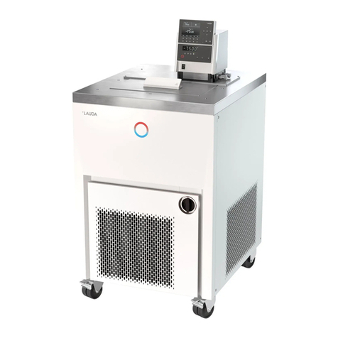
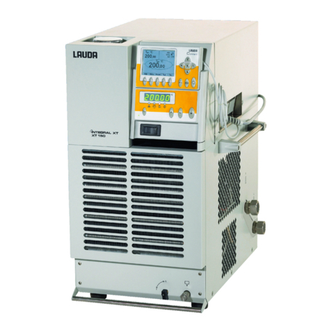
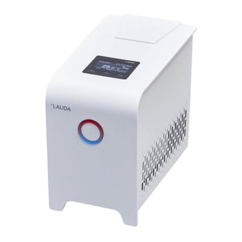
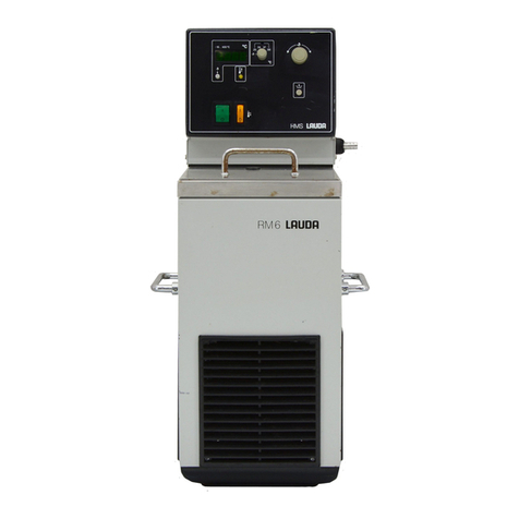
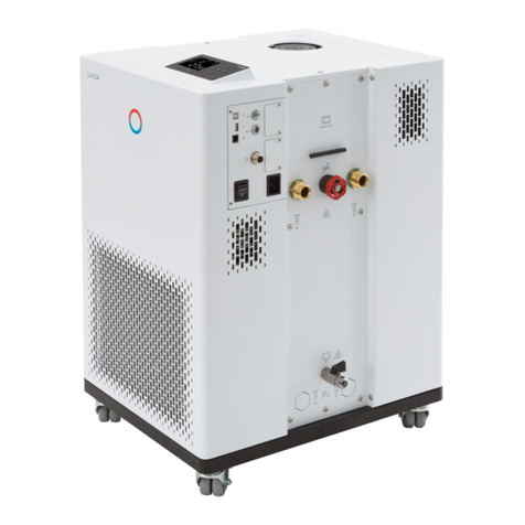
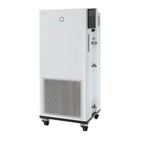
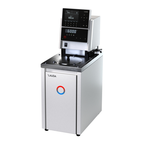
Lauda RP 4050 C User manual

Operation manual
PROLINE Kryomats
Low-temperature thermostats
with SmartCool System
RP 4050 C, RP 4050 CW
RP 3090 C, RP 3090 CW
RP 4090 C, RP 4090 CW
Release 03/2022 j Read the instructions before starting work!

2 / 137 Proline Kryomats 03/2022
Manufacturer
LAUDA DR. R. WOBSER GMBH & CO. KG
Laudaplatz 1
97922 Lauda-Königshofen
Germany
Phone: +49 (0)9343 503-0
Fax: +49 (0)9343 503-222
E-Mail info@lauda.de
Internet https://www.lauda.de
Translation of the original operating instructions Q4DA-E_13-010-EN;
replaces release 08/2020 i, 11/2018 e, 10/2018 d, 05/2016 b2, 03/13, 01/09, 06/08
Valid from:
software control system (Master) version 2.13
software safety system (Master) version 2.07
software operating system (Command) version 3.45
software chilling system version 2.13
software analog IO module version 3.14
software serial IO module version 3.22
software digital IO module version 3.14
software solenoid valve version 3.06
software Ethernet module version 1.23
software EtherCAT module version 1.06

03/2022 Proline Kryomats 3 / 137
Prefixed safety notes
Before operating the equipment, please read carefully all the instructions and safety notes in
Section 1.
If you have any questions, please phone us!
Follow the instructions on setting up, operation etc. This is the only way to avoid incorrect operation
of the equipment and to ensure full warranty protection.
The master head is supplied with power via the lower section of the unit. After switching off the
head using the switch at the front of the head and/or using the switch at the back of the head,
mains voltage is still present on the master head.
Switch off the unit by using the rotary switch on the front panel.
Switch off the equipment and pull out the mains plug:
for servicing or repair,
moving the equipment!
Transport the equipment with care!
The unit may NEVER be overturned nor put upside down!
Equipment and its internal parts can be damaged:
by dropping,
by shock.
Technically qualified personnel must only operate the equipment!
Never operate the equipment without the heat transfer liquid!
Do not start up the equipment if ...
it is damaged or leaking,
cable (not only supply cable) is damaged.
Drain the bath before moving the equipment!
Do not carry out any technical changes on the device!
Have the equipment serviced or repaired by properly qualified personnel only!
The Operating Instructions include additional safety notes, which are identified by a triangle with an exclamation
mark. Carefully read the instructions and follow them accurately! Disregarding the instructions may have serious
consequences, such as damage to the equipment, damage to property or injury to personnel!
We reserve the right to make technical alterations!

4 / 137 Proline Kryomats 03/2022
Contents
Prefixed safety notes.....................................................................................................................................................................3
1SAFETY INFORMATION ............................................................................................................................................8
1.1 SAFETY INFORMATION......................................................................................................................................................8
1.2 GENERAL SAFETY INFORMATION.....................................................................................................................................9
1.3 OTHER SAFETY INFORMATION...................................................................................................................................... 10
2BRIEF OPERATING INSTRUCTIONS .................................................................................................................. 11
2.1 MENU STRUCTURE:MASTER......................................................................................................................................... 12
2.2 MENU STRUCTURE:COMMAND REMOTE CONTROL.................................................................................................. 13
3CONTROLS AND FUNCTIONAL ELEMENTS................................................................................................... 14
4UNIT DESCRIPTION................................................................................................................................................. 18
4.1 ENVIRONMENTAL CONDITIONS.................................................................................................................................... 18
4.2 TYPES OF UNIT................................................................................................................................................................ 18
4.3 VARIOFLEX PUMP .......................................................................................................................................................... 18
4.4 MATERIALS..................................................................................................................................................................... 19
4.5 TEMPERATURE DISPLAY,CONTROL AND SAFETY CIRCUIT............................................................................................ 19
4.6 PROGRAMMER AND RAMP FUNCTION ......................................................................................................................... 20
4.7 INTERFACES ................................................................................................................................................................... 20
4.8 INTERFACE MODULES (ACCESSORIES)......................................................................................................................... 20
4.9 REFRIGERATING UNIT .................................................................................................................................................... 21
4.10 AVOIDANCE OF DEWING .............................................................................................................................................. 21
4.11 HEATER RATING AND POWER CONSUMPTION FROM THE MAINS............................................................................... 21
5UNPACKING .............................................................................................................................................................. 22
5.1 AFTER UNPACKING........................................................................................................................................................ 22
5.2 STANDARD ACCESSORIES............................................................................................................................................. 23
5.3 PACKING AND UNPACKING WITH ORIGINAL PACKAGING MATERIAL........................................................................... 23
5.3.1
Background.................................................................................................................................................................... 23
5.3.2
Requirements ................................................................................................................................................................ 23
5.3.3
Unpacking the device.................................................................................................................................................... 24
5.3.3.1 Outer cardboard box............................................................................................................................................ 24
5.3.3.2 Lift device from the pallet .................................................................................................................................... 25
5.3.4
Repacking with original packing material..................................................................................................................... 26
5.4 IN-PLANT TRANSPORT WITH HAND PELLET TRUCK OR FORK LIFTER............................................................................ 26
5.5 BEFORE PREPARATION ................................................................................................................................................. 27
6PREPARATION .......................................................................................................................................................... 28
6.1 ASSEMBLY AND SITING................................................................................................................................................... 28
6.2 FILLING AND DRAINING................................................................................................................................................. 29
6.3 CONNECTION OF THE COOLING WATER...................................................................................................................... 31
6.4 HEAT TRANSFER LIQUIDS,COOLING WATER AND HOSES ........................................................................................... 32
6.5 CONNECTING EXTERNAL LOADS .................................................................................................................................. 35
7STARTING UP............................................................................................................................................................. 37

03/2022 Proline Kryomats 5 / 137
7.1 MAINS CONNECTION.................................................................................................................................................... 39
7.2 SWITCHING ON.............................................................................................................................................................. 39
7.3 SWITCHING OFF /STANDBY .......................................................................................................................................... 41
7.4 KEY FUNCTIONS............................................................................................................................................................. 41
7.4.1
General key functions and pilot lamps......................................................................................................................... 41
7.4.2
Changing window information...................................................................................................................................... 45
7.4.3
Locking the keyboard.................................................................................................................................................... 46
7.5 IMPORTANT SETTINGS.................................................................................................................................................... 48
7.5.1
Temperature setpoint setting....................................................................................................................................... 48
7.5.2
Displaying the actual external temperature ................................................................................................................ 50
7.5.3
Setting pump power or standby ................................................................................................................................... 51
7.5.4
Activate external pump................................................................................................................................................. 53
7.5.5
Activating external control ........................................................................................................................................... 53
7.5.6
Current consumption from the mains......................................................................................................................... 55
7.5.7
Setting the date and time ............................................................................................................................................. 56
7.5.8
Display resolution setting ............................................................................................................................................. 57
7.6 SPECIAL SETTINGS.......................................................................................................................................................... 58
7.6.1
Defining the type of start mode................................................................................................................................... 58
7.6.2
Defining temperature limits ......................................................................................................................................... 59
7.6.3
Setpoint offset operating mode................................................................................................................................... 60
7.6.4
Restoring works settings............................................................................................................................................... 61
7.6.5
Setting the volume of the acoustic signals.................................................................................................................. 62
7.6.6
Entering the offset of the internal temperature probe.............................................................................................. 62
7.6.7
Restoring the works setting of the internal temperature-probe offset.................................................................... 63
7.6.8
Entering the offset of the external temperature probe ............................................................................................. 64
7.6.9
Restoring the works setting of the external temperature-probe offset................................................................... 64
7.7 GRAPHICAL DISPLAY OF TEMPERATURE MEASUREMENTS........................................................................................... 65
7.8 PROGRAMMER .............................................................................................................................................................. 67
7.8.1
Program example .......................................................................................................................................................... 67
7.8.2
Selecting and starting the program (Start, Hold, Stop)............................................................................................. 69
7.8.3
Interrupting, continuing or terminating the program (Hold, Continue, Stop) ........................................................ 70
7.8.4
Creating or modifying a program (Edit)...................................................................................................................... 71
7.8.5
Defining the number of program loops (Loops)......................................................................................................... 76
7.8.6
Viewing the program sequence as a graph (Graph) ................................................................................................... 76
7.8.7
Obtaining information on a program (Info) ................................................................................................................ 77
7.9 RAMP FUNCTION........................................................................................................................................................... 78
7.10 TIMER FUNCTION........................................................................................................................................................... 79
7.11 CONTROL PARAMETERS................................................................................................................................................ 80
7.11.1
Internal control variable (integral measurement probe) ............................................................................................ 81
7.11.1.1 Proven settings for control parameters and pump (integral measurement probe) ........................................ 81
7.11.2
External control variable (External measurement probe).......................................................................................... 81
7.11.2.1 Steps for setting the control parameters for external control.......................................................................... 82
7.11.3
Internal and external control parameter sets.............................................................................................................. 84
7.11.4
Self Adaption ................................................................................................................................................................. 85
7.12 ALARMS,WARNINGS AND ERRORS ............................................................................................................................. 88
7.12.1
Overtemperature protection and checking ................................................................................................................ 88
7.12.2
Low-level alarm and low-level checking...................................................................................................................... 90
7.12.3
High-level settings ........................................................................................................................................................ 91

6 / 137 Proline Kryomats 03/2022
7.12.4
High-level warning or alarm ......................................................................................................................................... 92
7.12.5
Pump-motor supervision: Overload or blockage ....................................................................................................... 93
7.12.6
Pump-motor supervision: Dry running ....................................................................................................................... 93
7.12.7
Compressor Overtemp................................................................................................................................................. 94
7.12.8
Three-phase current ..................................................................................................................................................... 94
7.12.9
Fault list „Alarms and Warnings“ ................................................................................................................................. 95
8INTERFACE MODULES........................................................................................................................................... 98
8.1 INSTALLING OF MODULES ............................................................................................................................................. 98
8.2 MENU STRUCTURE FOR ALL MODULES......................................................................................................................... 99
8.3 SERIAL INTERFACE RS 232/485...............................................................................................................................100
8.3.1
Connecting cables and interface test RS 232.........................................................................................................100
8.3.2
Protocol RS 232.........................................................................................................................................................101
8.3.3
Connecting cable RS 485 .........................................................................................................................................101
8.3.4
Protocol RS 485.........................................................................................................................................................102
8.3.5
Write commands (Data commands to the thermostat) ..........................................................................................102
8.3.6
Read commands (Data requested from the thermostat)........................................................................................104
8.3.7
Error messages ............................................................................................................................................................106
8.3.8
Driver software for LABVIEW® ...............................................................................................................................106
8.4 ANALOGUE MODULE...................................................................................................................................................107
8.5 CONTACT MODULE .....................................................................................................................................................108
8.5.1
Contact module LRZ 915 with three inputs and three outputs.............................................................................108
8.5.2
Namur-Contact module LRZ 914 with only one input and one output ...............................................................109
9MAINTENANCE.......................................................................................................................................................110
9.1 DEVICE STATUS ............................................................................................................................................................110
9.1.1
Interrogating the device type .....................................................................................................................................110
9.1.2
Software version ..........................................................................................................................................................110
9.1.3
Serial numbers .............................................................................................................................................................110
9.1.4
Device data ..................................................................................................................................................................110
9.1.5
Fault memory ..............................................................................................................................................................111
9.2 CLEANING....................................................................................................................................................................111
9.2.1
Cleaning the surface of the device ............................................................................................................................111
9.2.2
Draining the water-cooled condenser.......................................................................................................................112
9.3 SERVICING,CLEANING,REPAIR AND DISPOSAL INFORMATION................................................................................112
9.3.1
Servicing.......................................................................................................................................................................113
9.3.2
Service intervals...........................................................................................................................................................114
9.3.3
Testing the heat transfer liquid...................................................................................................................................114
9.3.4
Cleaning the condenser ..............................................................................................................................................115
9.3.4.1 Air-cooled condenser ........................................................................................................................................115
9.3.4.2 Water-cooled condenser...................................................................................................................................115
9.3.4.2.1 Cleaning the dirt trap.....................................................................................................................................115
9.3.4.2.2 Decalcifying the water cooling circuit ..........................................................................................................116
9.3.5
Repair information.......................................................................................................................................................116
9.3.6
Remedying faults.........................................................................................................................................................117
9.4 DISPOSAL INFORMATION............................................................................................................................................118
9.4.1
Disposal of the refrigerant..........................................................................................................................................118
9.4.2
Disposal of the packaging ...........................................................................................................................................119

03/2022 Proline Kryomats 7 / 137
9.5 HELP DESK AND ORDERING REPLACEMENT PARTS ...................................................................................................119
10 ACCESSORIES.........................................................................................................................................................120
11 TECHNICAL DATA AND DIAGRAMS................................................................................................................121
12 DECLARATION OF CONFORMITY AND PRODUCT RETURNS DECLARATION ...............................130
13 INDEX.........................................................................................................................................................................132

8 / 137 Proline Kryomats 03/2022
1Safety information
1.1 Safety information
Danger!
Type and source
Consequences of non-compliance
Action 1
Action ...
"DANGER" indicates an immediate dangerous situation which –if the safety requirements
are ignored –may result in fatal or severe, irreversible injuries.
Warning!
Type and source
Consequences of non-compliance
Action 1
Action ...
"WARNING" indicates a possible dangerous situation which –if the safety requirements are
ignored –may result in fatal or severe, irreversible injuries.
Caution!
Type and source
Consequences of non-compliance
Action 1
Action ...
"CAUTION" indicates a possible dangerous situation which –if the safety requirements are
ignored –may result in slight, reversible injuries.
Notice
Type and source
Consequences of non-compliance
Action 1
Action ...
"NOTICE" warns of possible property or environmental damage.

03/2022 Proline Kryomats 9 / 137
Reference
Refers to further information in other sections.
Note
Here special attention is drawn to some aspect.
1.2 General safety information
A heating and cooling thermostat heats or cools and circulates heat transfer liquids according to specified parameters.
This involves hazards due to high or low temperatures, fire and general hazards due to the application of electrical
energy.
The user is largely protected by the application of relevant standards.
Further hazard sources may arise due to the type of tempering medium, e.g. by exceeding or undercutting certain
temperature thresholds or by the breakage of the container and reaction with the heat transfer liquid.
It is not possible to consider all eventualities. They remain largely subject to the judgment and responsibility of the
operator.
The equipment must only be used as prescribed and as described in these operating instructions. This includes
operation by instructed specialist personnel.
The equipment is not rated for use under medical conditions according to DIN EN 60601-1 or IEC 601-1.
Classification in accordance with EMC requirements of DIN EN 61326-1
Device
Immunity
requirements
Emissions class
Customer power supply
Proline Kryomat
Table 2 (Industrial) in
accordance with
DIN EN 61326-1
Emissions Class B
in accordance with
CISPR 11
Only for EU
Domestic connection value
≥100 A
Proline Kryomat
Table 2 (Industrial) in
accordance with
DIN EN 61326-1
Emissions Class B
in accordance with
CISPR 11
Worldwide
No limitation
Only for the USA:
Instructions for Class A digital devices
“This equipment has been tested and found to comply with the limits for Class A digital device, pursuant to Part 15 of
the FCC (Federal Communication Commission) Rules. These limits are designed to provide reasonable protection
against harmful interference when the equipment is operated in a commercial environment. This equipment generates,
uses, and can radiate radio frequency energy and, if not installed and used in accordance with the instruction manual,
may cause harmful interference to radio communications. Operation of this equipment in a residential area is likely to
cause harmful interference in which case the user will be required to correct the interference at his own expense.”
“This device complies with Part 15 of the FCC (Federal Communication Commission) Rules. Operation is subject to
the following two conditions: (1) This device may not cause harmful interference, and (2) this device must accept any
interference received, including interference that may cause undesired operation.”
Only for Canada:
“This Class A digital apparatus complies with Canadian ICES-003” (ICES = Interference Causing Equipment

10 / 137 Proline Kryomats 03/2022
Standards).
« Cet appareil numérique de la Classe A est conforme à la norme NMB-003 du Canada ».
1.3 Other safety information
Only connect equipment to PE grounded mains sockets.
At higher operating temperatures, parts of the bath cover can reach surface temperatures exceeding 70 °C. Be
careful when touching it! Danger of burning!
Use suitable hoses (6.3).
Secure hose against slippage with the aid of hose clips. Avoid kinks in the hoses.
Check hoses from time to time for any possible material fatigue.
Thermal medium hoses and other hot parts must not come into contact with the mains cable.
With the use of thermostats as circulating thermostats hot or cold liquid can be emitted when the hose breaks,
presenting a hazard to persons and material.
If no external load is connected, the pump outflow must be closed (use screw plugs) and the bypass valve must be
set to "internal" (4.3).
Take into account the thermal expansion of the heat transfer oils with increasing bath temperature.
Irritant vapors may develop, depending on the heat transfer liquid and operating mode used. Always ensure that the
vapors are adequately extracted. Use the bath cover.
By changing the heat transfer liquid from aqueous heat transfer liquid to a thermal transfer liquid for temperatures
above 100 °C, carefully remove all water residues, including from the hoses and loads. When doing this, also open
the blanking caps of the pump outputs and inputs and blow compressed air through all the pump outputs and
inputs. Danger of scald due to delay in boiling!
Withdraw the mains plug before cleaning, maintenance or moving the thermostat.
Specialist personnel must only carry out repairs in the control section.
Figures of temperature constancy and display accuracy apply under normal conditions according to DIN 12876.
Electromagnetic high frequency fields may in special cases lead to unfavorable values. Safety is not impaired.
The following action may start the thermostat unintentionally from the standby mode: Previously activated timer
mode (7.10), "Start" command via interfaces (8).
Only water-cooled devices:
The return hose of the water-cooling must be securely fixed on the outlet port in order to prevent the hose sliding
off uncontrollably, also during pressure surges.
The return hose of the water-cooling must be fixed on the outlet port that hot cooling water cannot splash out.
It is essential to prevent kinking or squashing of the return hose for the water cooling. Excessive pressure can cause
the cooling water hoses to tear and hot water to escape.
To prevent damages by a leakage of the cooling water system its recommended to use a leak-water detector with
shut-off valve (Aqua Stop).

03/2022 Proline Kryomats 11 / 137
2Brief operating instructions
These brief instructions shall give you the possibility to operate the unit quickly. For safe operation of
the unit, it is necessary to read carefully all the instructions and safety notes!
1. Assemble unit and add items as appropriate (6.1).
The unit may NEVER be overturned nor put upside down!
Take care of the hose tubing connections (6.3 and 0).
2. Fill the unit with corresponding heat transfer liquid (6.3). The units are designed for operation with
non-flammable and flammable liquids to DIN EN 61010-2-010. Take care of the level of the heat
transfer liquid! (6.2).
3. Compare the information on the rating label with the supply details.
4. Connect the unit only to a socket with a protective earth (PE) connection.
5. Check whether the switch at the back of the master control element is in the "ON =
–" position.
6. Check whether the switch at the front of the master control element is in the "ON = l" position.
7. Set the rotary switch on the front panel to "ON = l". The unit starts operating.
8. With set the overtemperature cut-off point to a value clearly above room temperature (
7.12.1).
9. Now you see the current bath temperature in the
display, for example:
If instead, a warning or error message is displayed, then refer to Section 7.12.
Bath-temperature
02%32
°C

12 / 137 Proline Kryomats 03/2022
(7.5.3)
(7.5.4)
(7.5.1)
Display flashes. Set value
with or .
Display is accepted after 4 sec.
or proceed immediately
with the key: .
Bath temperature
2%32
°C
Pump power.5-8/Standby.0
Pu 8
°C
Setpoint
SEt
°C
Control Intern / Extern
Con 1
°C
Further settings
MNEmv
°C
Configure modules
MNpfv
°C
External temperature
2%02
°C
EXT
End
End
°C
Control parameters,
setpoint resolution,
setpoint-source input,
calibration, etc.
Protection system, Command,
cooling system, analog module,
RS 232 module and digital
module, etc.
Display flashes. Set setpoint
with or .
Display is accepted after 4 sec.
or proceed immediately
with the key: .
2.1 Menu structure: Master
These settings and configurations can be entered more easily and in a more clear manner via the Command remote
control. Therefore, for the Master control element they are not explained in more detail in this operating manual.

03/2022 Proline Kryomats 13 / 137
2.2 Menu structure: Command Remote Control
Menu
Display
Sounds Master
Sounds Command
Language
Master-Mode
Autostart
Current Consumpt.
Pump
Settings
Clock
Graph
Programmer
Interfaces 1
Control
Limits
Pump Level 0, 5…8
External pump
Start unfill condense.
Calibration
Works settings
Resolution
Device status
Display data
Basic settings
Overlevel handling
Set time
Set data
Timer 1
Timer 2
Format of date
Program 1
Program 2
Program 3
Program 4
Program 5
Ramp function
Serial Command
2serial Master /
Profibus
Analog interfaces
Switching contact
Smart Cool
Control parameters
Control para. sets
Tv manual/auto
Self Adaption
Correction limitation
Control variable
Control parameters
Setpoint offset
Max. Fan [%] 60
Brightness
Contrast
intern Pt100
extern Pt100
Device type
Software Version
Serial numbers
Device data
Error store
Mode
Baud rate
RS 485 address
internal
external Pt100
Analog interface
RS 232/485
Calibration
Default
Alarm
Warning
all default
Basic window
Standard window
Super window
Edit
Default
T il (min)
T ih (max)
Xp
Tn
Tv (auto)
Td (auto)
Kpe
Tne
Tve (auto)
Tde (auto)
Xpf
Prop_E(a)
Automatic
Manual
Status
Setpoint
Identification
Actual Parameters
off
external Pt100
RS 232
Status
Edit
Loops
Graph
Info
Start / Stop
Hold / continue
Modify
Erase
Show chart
Offset source
Setpoint offset
All Modules
Master
Command
Cool
Other connected
modules
English
Deutsch
Français
Español
All default
Only control par. int.
Only control par. ext.
Only miscellaneous
Display
Settings
Mode
Displayed value
Legend
Sample Time
Time axis
Time base
Temp. scale
Temp. limits
off
on
automatic
none
Warning
Warn. + Heater off
Alarm
Status
Temp. Change
Time
Time unit
18.2
2no menu in
Command
on
off
on

14 / 137 Proline Kryomats 03/2022
3Controls and functional elements
1Command remote control (see page 15)
2Master control element
3Pump connection on the side and Bypass valve
(see illustration on this page).
4Bath cover
5Rotary switch for power supply
6Grille (on both sides)
7Front cover (closed)
8Four steering transport rollers, two off them with
stoppers
1Pump connection on the side:
Pump outflow (pressure output)
closed off with screw
2Bypass valve (in "external" position)
3Pump connection on the side:
Suction nozzle (return to bath)
closed off with screw plug

03/2022 Proline Kryomats 15 / 137
With the front panel open, access to the drain cock:
1 Bath drain tap
2 Bath drain nozzle
1Bath edge heating and bath bridge heating
2Nameplate
3Mains cable
4Connection cable for control head
5Connection cable LiBus for control head
6Connection bath bridge heating
7Cooling water connections (at water-cooled
devices W only), connections as per pictogram

16 / 137 Proline Kryomats 03/2022
1Command remote control (see next page)
2Covers for the two module slots
3Connection socket 10S
for the external Pt100 temperature probe
4Connection socket LiBus (LAUDA internal bus) for bus
suitable for unit and to which the refrigerating lower section
and Command remote control are connected
5Mains switch
6Connection socket 51H
7Air intake for electronic head
8Pump connection rear and on the side:
Suction nozzle (return to bath) & pump outflow or
pressure output
refer to housing for label
9Mains connecting lead
10 Rear pump connections

03/2022 Proline Kryomats 17 / 137
Control element: Master
1Display
2The temperature of an external source is displayed
(EXT is lit green).
3Enter key
4Select keys
5Cooler active (blue LED is lit)
6Heater active (yellow LED is lit)
7Bath controlled by external temperature source
(green LED is lit)
8Error signal (red LED is blinking)
9Overtemperature set point to check or set Tmax
10 Mains On (green LED is lit)
Control element: Command
1Graphical display
2RS 232/485-socket (hidden on the back of
Command)
3Cursor keys
4Enter key
5Standby key; brings the thermostat into the idle mode
(Heater, refrigerating machine and pump are switched off,
yellow LED is lit).
6Escape key to quit a window without any changes
7Decimal point or "-" symbol
8Five soft-key duo-keys –their associated functions are
shown in the display.

18 / 137 Proline Kryomats 03/2022
4Unit description
4.1 Environmental conditions
The operation of the thermostats is only allowed under the following conditions as specified in
DIN EN 61010-2-010:2003 and DIN EN 61010-1:2001:
Indoor use only.
Altitude up to 2000 m above sea level.
Foundation must be dense, even, non-slippery and non-flammable.
Keep clear distance (6.1 Assembly and siting).
Ambient temperatures range (11 Technical data).
Use only within this range for an undisturbed operation.
Mains supply voltage fluctuations (11 Technical data).
Relative humidity (11 Technical data).
Transient over voltage according to Installation Categories (Over voltage Categories) II.
Pollution degree: 2.
4.2 Types of unit
The type designation of the Proline Kryomats comprises the prefix R (to designate the refrigeration machine), a P
for Proline, the bath volume in liters and the lowest bath temperature (guide figure without arithmetic sign).
The designation is supplemented with a "C" which indicates the presence of the Command remote control.
For units with water-cooling, the type designation is supplemented with a "W".
Examples: RP 4090 CW is a low-temperature thermostat with 40-liter bath and -90 °C lowest temperature.
The unit has a Command remote control and is water-cooled.
4.3 Varioflex pump
All units are fitted with a Varioflex pump with a 4-stage variable drive (pump level 5 to 8). The pump power can
therefore be optimally matched to the relevant task. In order to achieve optimum temperature homogeneity in the
heat transfer liquid in the bath, it is recommended to select the pump level in dependence of the viscosity of the heat
transfer liquid; therefore at higher viscosity to increase the pump level.
Be cautious at higher bath levels to avoid liquid to slop over the bath edge.
The user cannot set the pump levels 1 to 4, because there is no sufficient temperature homogeneity in the bath
vessel. With pump level 0 the unit goes into the standby mode. It should be noted that the heat input of the pump
into the bath increases with increasing pump level.
With the Varioflex pump, open containers can be operated at a constant level when a level controller (accessory LCZ
0660) is used.
At the right-hand side and at the back of the unit outflow and inflow nozzles of the pump are fitted for external loads.
This means that up to two external loads can be directly connected without a distributor. Pump connections, which
are not required, must be closed off with the supplied caps and union nuts.
A bypass valve can subdivide the total volume flow variably between the bath (internally) and the connected load
(externally). Attention: the external application must not block the volume flow. If no load is connected to the pump
connector, the bypass valve must be set to the “internal”position for the best bath circulation. All pump connections
must be closed off with the supplied caps and union nuts.

03/2022 Proline Kryomats 19 / 137
The pump connections on the unit are fitted with M16 x 1 thread.
The Varioflex pump operates short-term up to viscosity of 150 mm²/s. In the closed-loop control mode 50 mm²/s
should not be exceeded. The temperature control is the best with 30 mm²/s and lower viscosity.
For operation as a circulating thermostat with an external load, the highest possible power level is practicable to
maintain the temperature difference low, among other things also with higher temperatures in conjunction with oils
as heat transfer liquid.
Pump characteristics (11).
4.4 Materials
All parts being exposed to the heat transfer liquid are made of high quality material appropriate to the operating
temperature. Non-rusting stainless steel and high quality temperature-resistant, primarily solvent-resistant plastics are
used.
4.5 Temperature display, control and safety circuit
The Master control element is equipped with a 5-character green LED display, which is used for the display of the
measurements and settings, as well as the operating status. The entry of setpoints and other settings occurs under menu
guidance via four keys.
The more comfortable and removable Command remote control includes a backlit graphical display. The entry of the
setpoint and other settings occurs under menu guidance via situation-dependent cursor keys and soft keys.
A Pt100 temperature probe acquires the current temperature in the bath. A high-resolution A/D converter processes
the measurement. Further measurement conditioning occurs using a special control algorithm for controlling the heater
actuator, which has a low reactive effect on the mains, and the SmartCool refrigeration equipment together with
further transducers.
An external Pt100 temperature probe can be connected via a socket (10S) for the acquisition of an external
temperature. This value can be displayed and, if required, used as the controlled variable with external control (Master)
switched on. In this way, the system controls the external measurement and not the internal bath temperature (
7.5.4).
The safety system conforms to DIN EN 61010-2-010. The SelfCheck Assistant monitors about 50 unit parameters.
A dual-channel system is used in which two microcontrollers monitor one another. Along with the bath temperature
measurement and control probes, there are also two safety temperature probes (Pt100) for the safety circuit for the
overtemperature cut-off and for monitoring the bath temperature probe.
The overtemperature cut-off point is displayed on pressing the key on the Master.
Changing the overtemperature cut-off point: (7.2 Switching on) on page 39.
The bath level is acquired by the SelfCheck Assistant in 8 stages. If the minimum level is undercut, the pump, heater
and the SmartCool System refrigerating machine are switched off. The reaction of the thermostat in case of overfill can
be set to simply display a warning, to display a warning and switch off the heater or to switch off the unit completely with
pump, heater and SmartCool System refrigerating machine.

20 / 137 Proline Kryomats 03/2022
When the level is too low, with overtemperature, or with other alarms the SelfCheck Assistant switches the heater off
on all poles. The pump and the refrigerating machine are also switched off.
This switch-off under fault conditions is retained, i.e. after the fault is rectified, the fault must be reset (released) on the
Master operating panel with the key.
Other unit functions are described in the appropriate sections and in Section 7. (Starting up).
4.6 Programmer and ramp function
Master control element:
No programmer provided.
Command remote control:
The units are equipped with a programmer function, which enables five temperature/ time programs to be saved. Each
program consists of a number of temperature/ time segments. These also include details of how often the program is to
be executed. Up to 150 segments can be distributed amongst the five programs.
With the ramp function, a rate of change can be directly entered in K/ unit time (7.8).
4.7 Interfaces
The device is equipped in series with the following sockets:
One socket (10S) for the connection of an external Pt100 temperature probe.
Two sockets (70S) for the connection of components via the LAUDA equipment bus (cooling section, Command
remote control, external solenoid valve, etc.).
An RS 232/485 interface (65S) at the back of the Command remote control.
4.8 Interface modules (accessories)
The Master control element can be supplemented with further interface modules, which are simply inserted into two
module slots (3) at the back of the control head.
The following modules are currently available:
1. RS 232/485 Interface Module (Order No. LRZ 913) with 9-pole SUB-D socket. Electrically isolated
through optocouplers. Command set largely compatible with the Ecoline, Integral XT and Integral T Series. The
RS 232 interface can be directly connected to the PC with a cable wired 1:1 straight through (Order No.
EKS 037).
Further details can be found in section 8.3.
2. Analog Module (Order No. LRZ 912) with two inputs and two outputs on 6-pole DIN socket. The inputs and
outputs can be set independently as 4 –20 mA, 0 –20 mA or 0 –10 V interface.
Further details can be found in section 8.4.
This manual suits for next models
5
Table of contents
Other Lauda Thermostat manuals

Lauda
Lauda PROLINE P 5 C User manual

Lauda
Lauda ECO Silver E 4 S User manual

Lauda
Lauda Integral XT 150 User manual

Lauda
Lauda PTT User manual

Lauda
Lauda P 10 User manual

Lauda
Lauda Ecoline Series User manual

Lauda
Lauda RP 3050 C User manual

Lauda
Lauda RE 1050 G User manual

Lauda
Lauda Ecoline RE 320 User manual

Lauda
Lauda IN 550 XT User manual

Lauda
Lauda RCS 5 User manual

Lauda
Lauda P 10 User manual

Lauda
Lauda RE 212 J User manual

Lauda
Lauda RP 845 User manual

Lauda
Lauda L 100 User manual

Lauda
Lauda LOOP 100 User manual

Lauda
Lauda Alpha A User manual

Lauda
Lauda Ecoline RE 204 User manual

Lauda
Lauda IN 130 T User manual

Lauda
Lauda PROLINE P 5 C User manual