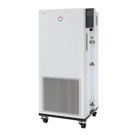
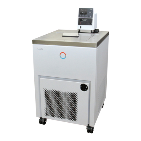
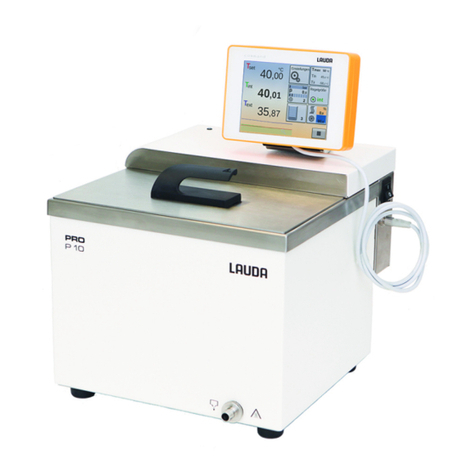
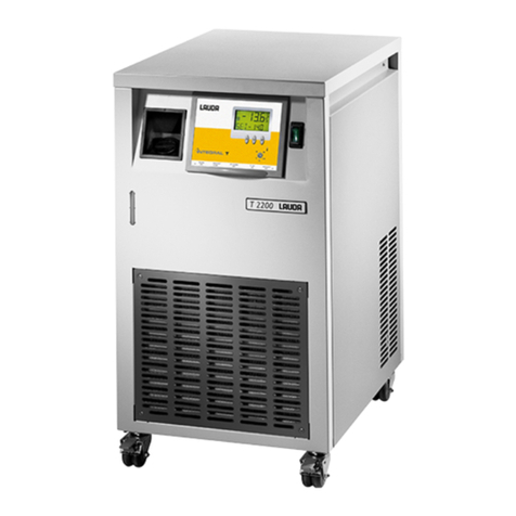
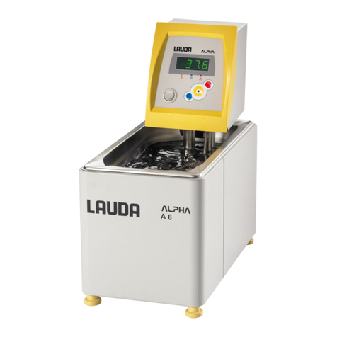
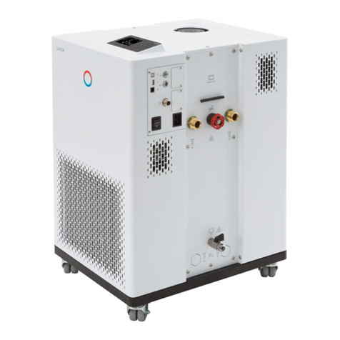
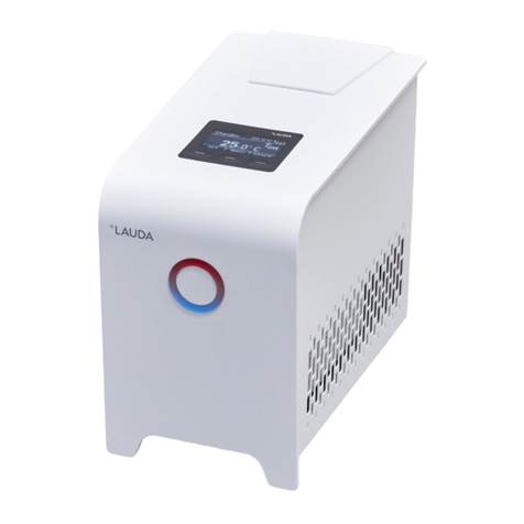
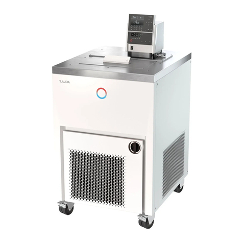
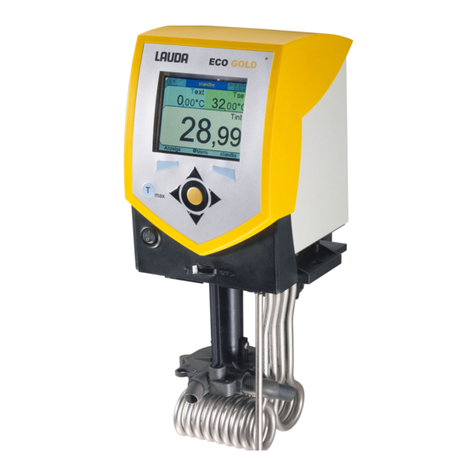
Lauda RE 1050 G User manual

Version 04/2010 b4
replaces version 02/2010 b3
YACE0088
LAUDA DR. R. WOBSER GMBH & CO. KG
Postfach 1251
97912 Lauda-Königshofen
Germany
Valid from:
Software Control System from Version 1.20
Software Safety System from Version 1.20
Software Chilling System from Version 1.20
Phone: (+49) 09343/ 503-0
Fax: (+49) 09343/ 503-222
e-mail [email protected]
Internet http://www.lauda.de
Operating Instructions
ECO GOLD
Heating and Cooling Thermostats with control head GOLD
Immersion thermostat
ECO GOLD
Heating thermostats
E 4 G, E 10 G, E 15 G, E 20 G, E 25 G, E 40 G,
ET 6 G, ET 12 G, ET 15 G, ET 20 G
Cooling thermostats
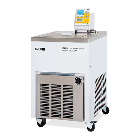
RE 415 G, RE 420 G, RE 620 G, RE 630 G, RE 1225 G, RE 2025 G, RE 1050 G


ECO GOLD
28.04.10/ YACE0088 First some safety information 3
First some safety information
Before you put the device into operation, read all the instructions and safety informa-
tion thoroughly. If you have any queries, please feel free to call us.
Follow the instructions about siting, setting up and operation as only then can im-
proper handling of the device be eliminated and the full warranty coverage main-
tained.
•Transport the device with care.
•The cooling thermostats should never be tilted nor stood upside down.
•The device can be damaged:
−by dropping,
−by vibration.
•The device may only be operated by appropriately instructed persons.
The operator must be of legal age. Persons not of legal age may only operate the
device under supervision of an instructed and legal age person.
•Never operate the device without heat transfer liquid.
•Do not operate the device, if:
−it is damaged,
−it is leaking,
−the mains cable is damaged.
•Switch off the device and withdraw the mains plug when:
−carrying out service or repair work,
−moving the device,
−installing or removing modules or accessories.
•Empty the bath before moving the device.
•Do not make technical modifications to the device.
•Have service and repair work carried out only by specialists.
The operating instructions contain additional safety information which is identified
with a triangle with an exclamation mark . Read the instructions thoroughly
and follow them. Ignoring the instructions can lead to severe consequences, e.g.
damage to the device or other property, or to personal injury.
Technical modifications reserved.

ECO GOLD
4Table of Contents 28.04.10/ YACE0088
Table of contents
1SAFETY INFORMATION........................................................................................................................................7
1.1 GENERAL SAFETY INFORMATION ........................................................................................................................... 7
1.2 OTHER SAFETY INFORMATION ............................................................................................................................... 8
2MENU STRUCTURE................................................................................................................................................. 9
3OPERATING AND FUNCTIONAL CONTROLS................................................................................................ 11
4DEVICE DESCRIPTION ........................................................................................................................................ 17
4.1 AMBIENT CONDITIONS ......................................................................................................................................... 17
4.2 DEVICE TYPES...................................................................................................................................................... 17
4.3 PUMP ................................................................................................................................................................... 17
4.4 MATERIALS ......................................................................................................................................................... 18
4.5 PROGRAMMER ..................................................................................................................................................... 18
4.6 INTERFACES......................................................................................................................................................... 18
4.7 INTERFACE MODULES (ACCESSORIES).................................................................................................................. 18
4.8 CHILLER .............................................................................................................................................................. 19
5UNPACKING............................................................................................................................................................ 20
6PREPARATIONS..................................................................................................................................................... 21
6.1 ASSEMBLY AND SITING........................................................................................................................................ 21
6.2 CONNECTION OF EXTERNAL LOADS ..................................................................................................................... 25
6.3 FILLING AND EMPTYING....................................................................................................................................... 27
6.4 HEAT TRANSFER LIQUIDS AND HOSES .................................................................................................................. 28
6.5 COOLING THE HEATING THERMOSTATS................................................................................................................ 30
7PUTTING THE DEVICE INTO OPERATION .................................................................................................... 31
7.1 MAINS CONNECTION............................................................................................................................................ 31
7.2 SWITCHING ON..................................................................................................................................................... 31
7.3 DISPLAY REPRESENTATION.................................................................................................................................. 33
7.3.1 Basic window .............................................................................................................................................. 33
7.3.2 Menu window.............................................................................................................................................. 33
7.3.3 Entry window .............................................................................................................................................. 35
7.3.4 Graphics window ........................................................................................................................................ 35
7.4 BASIC SETUP........................................................................................................................................................ 36
7.4.1 Setting the overtemperature switch-off point Tmax....................................................................................... 36
7.4.2 Setting the temperature setpoint value........................................................................................................ 36
7.4.3 Setting the pump level ................................................................................................................................. 37
7.4.4 Setting up standby....................................................................................................................................... 38
7.5 OTHER SETTINGS ................................................................................................................................................. 39
7.5.1 Defining temperature limits ........................................................................................................................ 39
7.5.2 Restoring factory settings............................................................................................................................ 40
7.5.3 Setting the volume of the acoustic signals................................................................................................... 40
7.5.4 Selecting the menu language....................................................................................................................... 41
7.5.5 Setting the chiller........................................................................................................................................ 41
7.5.6 Setting the display brightness...................................................................................................................... 42
7.5.7 Setting the date and time............................................................................................................................. 42
7.5.8 Defining the starting mode (Autostart) ....................................................................................................... 43
7.5.9 Limiting the mains current consumption..................................................................................................... 44
7.5.10 Entering the offset of the displayed temperature (calibration) ................................................................... 45
7.5.11 Restoring the factory setting of the internal temperature sensor (factory calibration)............................... 46
7.6 GRAPHICAL DISPLAY OF TEMPERATURE MEASUREMENTS.................................................................................... 47
7.7 EXTERNAL CONTROL ........................................................................................................................................... 50
7.7.1 Activating external control (external Pt100)............................................................................................... 50
7.7.2 Setpoint offset operating mode (Diff.set/actual).......................................................................................... 51
7.8 PROGRAMMER ..................................................................................................................................................... 52
7.8.1 Programming example................................................................................................................................ 52

ECO GOLD
28.04.10/ YACE0088 Table of contents 5
7.8.2 Creating or changing a program (editing) ..................................................................................................53
7.8.3 Starting the program....................................................................................................................................56
7.8.4 Interrupting, continuing or terminating the program..................................................................................56
7.8.5 Defining the number of program loops (Loops) ..........................................................................................57
7.9 CONTROL PARAMETERS........................................................................................................................................58
7.9.1 Internal control variable (internal temperature sensor)..............................................................................58
7.9.2 External control variable.............................................................................................................................60
7.9.2.1 Setting the correcting quantity limit.........................................................................................................62
7.9.2.2 Procedure for setting the control parameters for external control............................................................63
8INTERFACE MODULES.........................................................................................................................................64
8.1 INSTALLATION OF MODULES.................................................................................................................................64
8.2 MENU STRUCTURE OF THE MODULES....................................................................................................................66
8.3 ANALOGUE MODULE.............................................................................................................................................67
8.4 RS 232/485 INTERFACE MODULE..........................................................................................................................68
8.4.1 Connecting lead and interface test RS 232..................................................................................................68
8.4.2 RS 232 protocol ...........................................................................................................................................69
8.4.3 RS 485 connecting lead................................................................................................................................69
8.4.4 RS 485 protocol ...........................................................................................................................................70
8.5 USB INTERFACE ...................................................................................................................................................71
8.5.1 Description ..................................................................................................................................................71
8.5.2 Installation of the USB driver......................................................................................................................71
8.5.3 Connecting the thermostat to the PC...........................................................................................................72
8.5.4 Where is the ECO Virtual COM Port? ........................................................................................................74
8.6 COMMANDS AND ERROR MESSAGES APPLICABLE TO THE RS 232/485 INTERFACE MODULE AND TO THE USB
INTERFACE........................................................................................................................................................................76
8.6.1 Write commands (data issued to the thermostat).........................................................................................76
8.6.2 Read commands (data request from the thermostat) ...................................................................................77
8.6.3 Error messages............................................................................................................................................79
8.6.4 Driver software for LABVIEW®..................................................................................................................79
8.7 CONTACT MODULE ...............................................................................................................................................80
8.7.1 Contact module LRZ 914 with 1 input and 1 output....................................................................................80
8.7.2 Contact module LRZ 915 with 3 inputs and 3 outputs.................................................................................81
9MAINTENANCE.......................................................................................................................................................82
9.1 ALARMS,WARNINGS AND ERRORS........................................................................................................................82
9.1.1 Overtemperature protection alarm and overtemperature protection check ................................................82
9.1.2 Low level protection alarm and low level protection check.........................................................................83
9.2 CLEANING ............................................................................................................................................................84
9.3 DEVICE STATUS ....................................................................................................................................................84
9.3.1 Error store...................................................................................................................................................85
9.3.2 Device data..................................................................................................................................................85
9.3.3 Software version ..........................................................................................................................................85
9.3.4 Displaying and changing the device type.....................................................................................................86
9.3.5 Displaying serial numbers...........................................................................................................................86
9.4 SERVICING AND REPAIR........................................................................................................................................87
9.4.1 Servicing intervals to VDI 3033...................................................................................................................87
9.4.2 Inspecting the heat transfer liquid...............................................................................................................87
9.4.3 Cleaning the condenser................................................................................................................................87
9.5 DISPOSAL INFORMATION ......................................................................................................................................88
9.5.1 Disposal of the coolant ................................................................................................................................88
9.5.2 Disposal of the packaging............................................................................................................................88
9.6 ORDERING REPLACEMENT PARTS..........................................................................................................................89
10 ACCESSORIES.........................................................................................................................................................90
11 TECHNICAL DATA AND GRAPHS......................................................................................................................92
12 INDEX ........................................................................................................................................................................99
CONFIRMATION……………………………………………………………………………………………………….101
ECO GOLD
6Special Symbols 28.04.10/ YACE0088
Special symbols:
Caution: This sign is used when improper handling can lead to
personal injury or damage to property.
Note: Here, something in particular needs the reader's atten-
tion. In certain circumstances this includes a note about
a hazard.
Ì
Reference Refers to further information in other chapters.

ECO GOLD
28.04.10/ YACE0088 Safety information 7
1 Safety information
1.1 General safety information
A laboratory thermostat is used to heat, cool and circulate liquids as specified. Hazards arise from this
due to high or low temperatures, fire and the general hazards due to the application of electrical en-
ergy.
The user is largely protected by the application of the relevant standards.
Further hazard sources can arise from the type of material for which the temperature is to be stabilized,
e.g. with the exceeding or undercutting certain temperature thresholds or with the fracture of the con-
tainer and reaction with the heat transfer liquid. It is not feasible to include all possible situations. They
remain essentially subject to the judgement and responsibility of the operator.
The devices may only be used as intended, that is as described in this operating manual. This includes
operation by instructed specialist personnel.
The devices are not designed for use under medical conditions according to DIN EN 60601-1 or IEC
601-1.
Classes in the EMC standard DIN EN 61326-1.
Class A: Operation only on electrical supply networks without connected domestic areas.
Class B: Equipment for operation on electrical supply networks with connected domestic areas.
With unfavourable network conditions interfering voltage variations can occur.
Class of protection for electrical oper-
ating equipment
DIN EN 61140 (VDE 0140-1) Class I
EMC requirements to DIN EN 61326-
1 (corresponds to VDE 0843-20-1)
applies to Europe Class B
for Canada and the USA Class A
EC directives The devices conform to the directives of the European Parlia-
ment and of the Council: 2004/108/EC regarding electromag-
netic compatibility (EMC) and 2006/95/EC relating to electrical
operating equipment for use within certain voltage limits (Low
Voltage Directive).
The devices bear the CE label.
Usage restriction
For the EMC standard DIN EN 61326-1:
Devices in Class A are only to be operated on electrical supply networks without connected
domestic areas.

ECO GOLD
8Safety information 28.04.10/ YACE0088
1.2 Other safety information
•Check the device carefully for shipping damage before putting into operation. The device should not
be put into operation if shipping damage has been found.
•Only connect devices to earthed mains sockets.
•At higher operating temperatures parts of the bath cover can take on surface temperatures of over
70 °C. Be careful when touching the device.
•Use suitable hoses (Ì6.4).
•Secure hoses against slippage by using hose clips. Avoid kinking the hoses.
•Check the hoses from time to time for any material fatigue.
•Hoses with hot heat transfer liquid and other hot parts must not come into contact with the mains
cable.
•When using the thermostat as a circulation thermostat, hot liquid can escape due to hose fracture
and become a danger to personnel and materials.
•If no external load is connected, the feed nozzle must be sealed off (use the sealing plug) or short-
circuit it to the return nozzle.
•Pay attention to the thermal expansion of the heat transfer liquid with increasing bath temperature.
•Toxic vapours may be generated depending on the heat transfer liquid used and the operating mode.
Ensure adequate air extraction.
•Attach immersion thermostats carefully to the bath vessel.
•Only use bath vessels which are suitable for the intended operating temperatures.
•Always set the overtemperature cut-off point immediately according to the heat transfer liquid used
when filling.
•When changing the heat transfer liquid from water to other liquids for temperatures above 100 °C,
carefully remove all residues of water including from the hoses and loads, otherwise there is a risk of
scalding due to delay in boiling.
•Use cooling coils with cooling water only for operating temperatures below 100 °C, because with
higher temperatures there is the risk of superheated steam forming.
•Withdraw the mains plug before cleaning, servicing, installing or removing modules or moving the
thermostat.
•Have repairs to the control section carried out only by specialists.
•Keep to service and maintenance intervals according to VDI 3033 (Ì9.4.1).
•The figures in the technical data apply under standard conditions according to DIN 12876. Electro-
magnetic high frequency fields can in special cases lead to unfavourable values. Safety is not impai-
red.

ECO GOLD
28.04.10/ YACE0088 Menu structure 9
2 Menu structure
Menu structure of Control Head GOLD
Stage 6
Stage 5 internal Pt100
Stage 4 external Pt100
Stage 3
Stage 2 internal Pt100 Xp
Stage 1 external Pt100 Tn
Tv
Control Variable manual/autom.
Control parameter Tv
Control para. sets Offset source Td
Setpoint offset Diff.set/actual value20.0
Correction limit.10.0
Alarm Kpe
off Warn Tne
on Errors Xpf
automatic Tv
Pump Level Brightness manual/autom.
Control T il Tve
Menu Cooling autom. T ih off Tde
Temp. Limits on Prop E
Basic setup Acoustic signal
Calibration Display English off
Factory Setting Autostart Deutsch external Pt100
Device Status Display resolution Français
Curr.consumpt. Español
Setpoint Value DLK connected Italiano loud
Setup Language Русский medium
Programmer low
Interfaces Calibration no off
Graph Factory calibration yes
Clock
Standby all default no automatic
Control yes Stage 5
Stage 4
Error store Reset all Stage 3
Program 1 Device data ctrl. parameter intern Stage 2
Program 2 SW version ctrl. parameter extern Stage 1
Program 3 Type internal Pt100 off
Program 4 Serial numbers miscellaneous
Program 5
Status Start no
Edit yes
Section 8.2 Loops Hold
Info Stop
Continue
Stop
1 Correcting quantity limit
2 Difference setpoint/actual value
Continued on following page

ECO GOLD
10 Menu structure 28.04.10/ YACE0088
Continued from previous page
Menu
Online graph
Record Start
Freeze Graph Start
Setpoint Value Tset Tint Text
Setup Tset Tint
Programmer Tset Text
Interfaces Section 8.2 Tint Text
Graph Tint
Clock Text
Standby Tset
Mode
Displayed Value
Sample Time 2 s (max.2h10min)
Time Axis 10 s (max.11h5min)
Time Base 30 s (max.33h20min)
Temperature Scale 1 min (max.66h40min)
Temperature Limits 2 min (max.133h)
automatic
9 min
45 min
Set time and date 2 h 15 min
Timer 1
Timer 2
Format of date absolut
relativ
automatic
manual
Temp. Scale min
Temp. Scale max
DD . MM . YYYY
MM / DD / YYYY

ECO GOLD
28.04.10/ YACE0088 Operating and functional controls 11
3 Operating and functional controls
Control Head ECO GOLD (can be used as immersion thermostat with screw clamp)
1
2
3
4
5
6
7
8
9
1 Mains switch
2 Light sensor for automatic control of display brightness
3 Colour TFT display
4 Control panel (refer to page 16)
5 Selector switch for dividing up the external and internal pump flow
6 Pump output for internal bath circulation
7 Pump output for bath circulation or connection to the pump connection set
8 Pt100 temperature sensor
9 Heater

ECO GOLD
12 Operating and functional controls 28.04.10/ YACE0088
Rear view of Control Head ECO GOLD
1
2
3
4
5
6
7
1 Mini-USB interface (Ì4.6)
2 Upper module receptacle approx. 51x27 mm for analogue, RS 232/485, Profibus module and contact
modules
3 Lower module receptacle approx. 51x17 mm for Pt100/LiBus module
4 Connection for control cable of cooling underpart for RE 1050 G
5 Connection of power supply between the control head and cooling underpart
6 Rating label
7 Mains connecting lead

ECO GOLD
28.04.10/ YACE0088 Operating and functional controls 13
Heating Thermostats ECO GOLD
1
2
3
4
1 Cooling coil connections
2 Pump connection: outflow and return (as standard only with E 4 G and ET 15 G)
3 Bath cover (as standard only with E 4 G)
4 Four feet
1
2
3
4
1 Rating label
2 Mains connecting lead
3 Bath drain tap
4 Bath drain point

ECO GOLD
28.04.10/ YACE0088 Operating and functional controls 15
1
2
3
4
5
6
7
1 Connecting lead between the control head and cooling underpart
2 Back grip recess
3 Rating label
4 Control cable for cooling underpart (only with RE 1050 G)
5 Bath drain tap
6 Bath drain point
7 Ventilation grill

ECO GOLD
16 Operating and functional controls 28.04.10/ YACE0088
Control panel and display ECO GOLD
Display
1
2
3
4
Control panel
5
6
7
8
Display Control panel
1 Expanded status display 5 Soft keys, left and right
2 Status display 6 Enter key or soft key, centre
3 Display of the internal or external
temperature value (Tint or Text) 7 Cursor keys
Cursor keys for Up, Down, Left and
Right.
4 Soft-key bar
8 Key Tmax
Display and adjustment of the over-
temperature switch-off point

ECO GOLD
28.04.10/ YACE0088 Device description 17
4 Device description
4.1 Ambient conditions
Use of the thermostating unit is only admissible under the conditions stated in
DIN EN 61010-1:2001 and DIN EN 61010-2-010:2003 :
−Operation only indoors.
−Elevation up to 2000 m above seal level.
−Siting base impermeable, flat, non-slip and non-flammable.
−Keep distance to walls (Ì6.1).
−Ambient temperature (Ì11).
The ambient temperature must be taken into account.
−Permissible mains voltage variations (Ì11).
−Maximum relative humidity 80 % up to 31 °C and decreasing linearly to 50 % up to 40 °C.
−Overvoltage Category II and transient overvoltages according to Category II.
−Contamination Level: 2.
4.2 Device types
Heating thermostats
The type designation of the heating thermostats is composed of the prefix E for ECO, the approximate
bath volume in litres and a G for the GOLD device variant.
Example: E 10 G is a heating thermostat with a maximum bath volume of 10 litres in the GOLD device
variant.
With the heating thermostats with a transparent bath there is the prefix of ET for the ECO transparent
bath, followed by the bath volume in litres and a G for the device variant GOLD.
Example: ET 6 G is a heating thermostat with a transparent bath with a maximum bath volume of 6 litres
in the GOLD device variant.
Cooling thermostats
The type designation of cooling thermostats is composed of the prefix R (to identify the cooling device:
Refrigerated), an E for ECO, the bath volume in litres, the minimum attainable temperature (without ar-
ithmetical sign) and a G for the device variant GOLD.
Example: RE 415 G is a heating thermostat with a maximum bath volume of 4 litres and a minimum tem-
perature of -15 °C.
4.3 Pump
All devices are equipped with a pressure pump. The pump has an output with a pivotable outflow elbow.
With the bath and circulation thermostats this is joined to the pump set for external tempering circuits. An
additional output is used for internal bath circulation. By switching the selector at the front on the control
head, the flow can be manually selected or divided between the two outputs.
In the heating range the pump operates up to viscosities of 150 mm²/s. In the controlled mode 30 mm²/s
should not be exceeded.
Using the operating menu, one of six flow-rate levels can be selected for the pump. For small bath ther-
mostats a power level of 1 to 3 is practicable.
When operated as a circulation thermostat with an external load, a higher power level is practicable to
keep the temperature difference between the bath and external load small even at higher temperatures.
The pump connection of the outflow can be closed without any detrimental effects on the pump.
Pump characteristics (Ì11)

ECO GOLD
18 Device description 28.04.10/ YACE0088
4.4 Materials
All parts coming into contact with the heat transfer liquid are made of high quality material suitable for the
operating temperature. Non-rusting stainless steel, and temperature-resistant and to a large extent sol-
vent-resistant plastics are used.
4.5 Programmer
The devices are equipped with a programming function. This function provides five temperature/time
programs. Up to 150 segments can be spread over the five programs. (Ì7.8).
4.6 Interfaces
In the basic version the GOLD devices are equipped with a mini-USB interface. This enables, for exam-
ple, the connection of a PC and operation with the thermostat control software Wintherm Plus. In addi-
tion software updates are possible via the USB interface. The connecting lead is not included in the
items supplied with the thermostat. When connecting up, make sure the correct plug is used.
4.7 Interface modules (accessories)
The devices can be supplemented with further interface modules which are connected to the rear of the
control head in two module slots (Ì8) and are inserted.
The following modules are currently available:
1. Analogue Module (LAUDA order no. LRZ 912) with two inputs and two outputs on a six-pole
DIN socket. The inputs and outputs can be set independently of one another as a 4...20 mA
or 0...10 V interface. 20 V is brought out on the socket as a power supply for an external sen-
sor with evaluation electronics.
2. RS 232/485 Interface Module (LAUDA order no. LRZ 913) with nine-pole SUB-D socket.
Electrically isolated using optocouplers. Using the LAUDA instruction set, extensively com-
patible to Proline, Proline Kryomat, Integral XT and Integral T series. The RS232 interface
can be connected directly to the PC with a 1:1 connected cable (LAUDA order no. EKS 037).
3. Contact Module (LAUDA order no. LRZ 914) with connector to NAMUR NE28. Range of
functions as for LRZ 915, but only one output and one input on each of two DIN sockets.
Coupling Socket three-pole, (LAUDA order no. EQD 047) and Coupling Plug three-pole,
(LAUDA order no. EQS 048).
4. Contact Module (LAUDA order no. LRZ 915) for 15-pole SUB-D socket. With three relay
contact outputs (changeover, max. 30V/0.2A) and three binary inputs for control via external
voltage-free contacts. Plug 15-pole, (LAUDA order no. EQM 030) and Plug Housing (LAUDA
order no. EQG 017).
5. Profibus Module (LAUDA order no. LRZ 917).
You will find further information in the Operating Instructions YAAD0020 for the Profibus
Module.
6. Pt100/LiBus Module (LAUDA order no. LRZ 918)
External Pt100: For the connection of an external temperature sensor.
LiBus: For the connection of the Command remote control unit from the Proline
equipment line and other accessories, such as a solenoid valve for cooling water control, a
reverse-flow protection device or a through-flow cooler (DLK) with LiBus connection.

ECO GOLD
28.04.10/ YACE0088 Device description 19
4.8 Chiller
The chiller mainly consists of a fully hermetically sealed compressor. The dissipation of the condensation
and motor heat takes place via a fan-ventilated lamellar condenser. Here, atmospheric air is drawn in at
the front of the device, heated up and discharged at the back and sides. To ensure proper air circulation
the ventilation openings must not be covered up.
The compressor is equipped with a thermal release which responds to the compressor temperature and
current consumption. The chiller is normally switched in automatically, but can also be switched in
manually via the operating menu (Ì7.5.5).
The chiller is switched off when a malfunction occurs which affects safety.
The Cooling Thermostat RE 1050 G is equipped with the SmartCool technology which makes optimum
use of the compressor and only chills when cooling output is demanded by the controller. To achieve
this, several sensors in the cooling circuit monitor the operating status.
Cooling times for the various cooling thermostats can be taken from the cooling curves (Ì11).

ECO GOLD
20 Unpacking 28.04.10/ YACE0088
5 Unpacking
After unpacking, first check the device and accessories for any transport damage. If contrary to expecta-
tions the device is found to be damaged, the shipping company must be immediately informed so that
verification can take place.
Please also inform LAUDA Service Constant Temperature Equipment (Ì9.6).
Standard accessories:
Order number Quantity Description Included with
HDQ 132 1 Bath Cover E 4 E 4 G
HDQ 127 1 Bath Cover RE 415, RE 420 RE 415 G and RE 420 G
HDQ 128 1 Bath Cover RE 620, RE 630 RE 620 G and RE 630 G
HDQ 129 1 Bath Cover RE 1050 RE 1050 G
HDQ 130 1 Bath Cover RE 1225 RE 1225 G
HDQ 131 1 Bath Cover RE 2025 RE 2025 G
LCZ 0716 1 Pump Connection Set RE (cooling) devices, E 4 G, ET 15 G
HKO 026 2 Olive Ø 13 mm RE (cooling) devices, E 4 G, ET 15 G
HKM 032 2 Union Nuts M16x1 RE (cooling) devices, E 4 G, ET 15 G
HKN 065 2 Sealing Plug RE (cooling) devices, E 4 G, ET 15 G
LCZ 0720 1 Cooling Coil E 4 G, ET 6 G
LCZ 0721 1 Cooling Coil E 10 G, E 15 G, E 20 G, E 25 G, E 40 G,
ET 12 G, ET 20 G
EZB 260
1
Warning Label "HOT"
All thermostats
Note: Attach to an easily visible point on the
bath for applications above 70 °C
YACE0088 1
Operating Instructions (this
document) All GOLD thermostats
This manual suits for next models
3
Table of contents
Other Lauda Thermostat manuals

Lauda
Lauda Proline RP 845 C User manual

Lauda
Lauda L 100 User manual

Lauda
Lauda E 4 G User manual

Lauda
Lauda PROLINE P 5 C User manual

Lauda
Lauda LOOP 100 User manual

Lauda
Lauda PTT User manual

Lauda
Lauda Alpha User manual

Lauda
Lauda Ecoline E 200 User manual

Lauda
Lauda RE 104 User manual

Lauda
Lauda ECO Silver E 4 S User manual

Lauda
Lauda PROLINE Kryomats Series User manual

Lauda
Lauda P 10 User manual

Lauda
Lauda RCS 5 User manual

Lauda
Lauda Ecoline RE 204 User manual

Lauda
Lauda RE 212 J User manual

Lauda
Lauda RM 6 T User manual

Lauda
Lauda Viscotemp 15 G User manual

Lauda
Lauda RP 845 User manual

Lauda
Lauda IN 130 T User manual

Lauda
Lauda RA 12 User manual