Lauda Ecoline RE 204 User manual

LAUDA DR. R. WOBSER
GMBH & CO. KG
P.O. Box 1251
97912 Lauda-Königshofen
Germany
From Series A 20 (see item 8.3)
from Software version 3.4
02/03
YACE0060
Phone: (+49) (0) 9343/ 503-0
Fax: (+49) (0) 9343/ 503-222
e-mail [email protected]
Internet http://www.lauda.de
Operating Instructions
Ecoline
Low-temperature thermostats
RE 204, RE 206, RE 207,
RE 210, RE 212, RE 220


I
Safety notes
Before operating the equipment please read carefully all the instructions and safety
notes.
If you have any questions please phone us!
Follow the instructions on setting up, operation etc. This is the only way to avoid
incorrect operation of the equipment and to ensure full warranty protection.
•Transport the equipment with care!
•Equipment and its internal parts can be damaged:
−by dropping
−by shock.
•Equipment should only be operated by technically qualified personnel!
•Never operate the equipment without the bath liquid!
•Do not start up the equipment if
−it is damaged or leaking
−the supply cable is damaged.
•Switch off the equipment and pull out the mains plug for
−servicing or repair
−the supply cable is damaged!
•Drain the bath before moving the equipment!
•Have the equipment serviced or repaired by properly qualified personnel only!
The Operating Instructions include additional safety notes which are identified by a
triangle with an exclamation mark. Carefully read the instructions and follow them
accurately! Disregarding the instructions may have serious consequences, such as
damage to the equipment, damage to property or injury to personnel
We reserve the right to make technical alterations!

II
1 BRIEF OPERATING INSTRUCTIONS.......................................................................................1
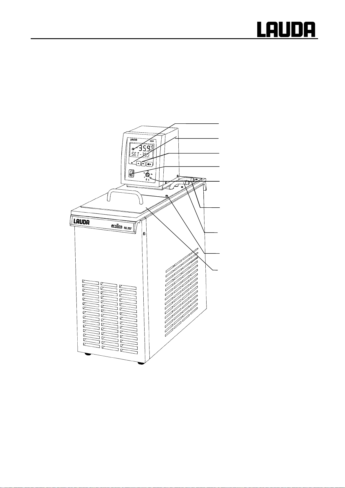
2 CONTROL AND FUNCTIONAL ELEMENTS.............................................................................3
3 UNIT DESCRIPTION..................................................................................................................4
3.1 Unit types ...........................................................................................................................4
3.2 Pumps.................................................................................................................................4
3.3 Temperature indication, control, and safety circuit........................................................ 4
3.4 Materials.............................................................................................................................5
3.5 Refrigeration system.........................................................................................................5
3.6 Serial Interfaces RS 232, RS 485 ......................................................................................6
3.6.1 RS 232 Interface ............................................................................................................................6
3.6.2 RS 485 Interface ............................................................................................................................8
3.6.3 Write commands (data commands to the thermostat)............................................................10
3.6.4 Read commands (data requested from thermostat)................................................................11
3.6.5 Error messages...........................................................................................................................12
3.6.6 Driver software for LABVIEW®...................................................................................................12
4 UNPACKING............................................................................................................................13
5 PREPARATIONS.....................................................................................................................14
5.1 Assembly and setting up................................................................................................. 14
5.2 Filling and emptying........................................................................................................15
5.3 Bath liquids and hose connections................................................................................ 17
5.4 Connection of external circuits ......................................................................................19
6 STARTING UP.........................................................................................................................20
6.1 Connection to the supply................................................................................................20
6.2 Switching on .................................................................................................................... 20
6.3 Setpoint selection (level 0) .............................................................................................. 21
6.4 Menu functions................................................................................................................22
6.4.1 Refrigeration system (level 1).....................................................................................................22
6.4.2 Pump output................................................................................................................................23
6.4.3 Setting the setpoint resolution..................................................................................................24
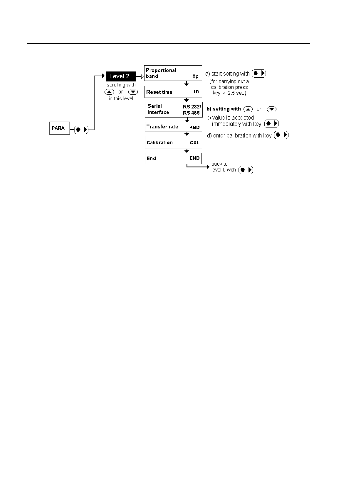
6.4.4 Parameters...................................................................................................................................25
6.4.4.1 Setting the proportional band of the PID-controller ...................................................................26
6.4.4.2 Setting the reset time of the PID-controller................................................................................27

III
6.4.4.3 Selection of the interface...........................................................................................................28
6.4.4.4 Setting the Baud rate/ transfer rate (serial interface) ................................................................29
6.4.4.5 User calibration..........................................................................................................................30
6.5 Warning and safety functions.........................................................................................31
6.5.1 Overtemperature protection and testing..................................................................................31
6.5.2 Low-level protection and testing...............................................................................................33
6.5.3 Pump motor monitoring.............................................................................................................34
6.5.4 Connection floating contact ”Combination fault” 31 N ..........................................................34
6.5.5 Other error messages.................................................................................................................35
7 SAFETY NOTES......................................................................................................................36
7.1 General safety notes........................................................................................................36
7.2 Other safety notes ...........................................................................................................36
8 MAINTENANCE.......................................................................................................................38
8.1 Cleaning............................................................................................................................38
8.2 Maintenance and repair...................................................................................................38
8.2.1 Maintenance of the refrigeration unit .......................................................................................39
8.2.2 Note on repair and disposal.......................................................................................................39
8.3 Ordering spares...............................................................................................................39
9 TECHNICAL DATA (TO DIN 58966)........................................................................................40
10 ACCESSORIES....................................................................................................................43
11 CIRCUIT DIAGRAM..............................................................................................................44
12 PIPE PLAN...........................................................................................................................48

IV
Explanation of signs
Danger: This sign is used where there may be injury to
personnel if a recommendation is not followed
accurately or is disregarded.
☞Note Here special attention is drawn to some aspect. May
include reference to danger.
➾Reference: Refers to other information in different Sections.

Brief operating instructions
15.05.01
YACE0060 1
1 Brief operating instructions
This brief instruction shall give you the possibility to operate the unit quickly. For safe operation
of the unit it is absolutely necessary to read carefully all the instructions and safety notes!
1. Assemble unit and add items as appropriate (➾Section 5).
Take care of the hose tubing connections (➾Section 5.1. and 5.4.).
2. Fill the unit with corresponding liquid. (➾Section 5.3.).
The units are designed for operation with non-flammable and flammable liquids to
EN 61010-2-010. !Take care of the level of the bath liquid! (➾Section 5.2.)
3. Connect the unit only to a socket with a protective earth (PE) connection.
Compare the information on the rating label with the supply details.
4. Using a screwdriver, set the overtemperature cut-out point to a value clearly
above ambient temperature (➾Section 6.5.1.).
5. Switch on at the mains switch
6. Setting of the functions

Brief operating instructions
2

Control and functional elements
15.05.01
YACE0060 3
2 Control and functional elements
Cooling
LED green, Supply ON
Menu functions
Mains switch
Setting of the overtemperature
switch-off point
Pump connections
−return
Pump connection:
−outflow
Bath bridge
Bath cover

Unit description
4
3 Unit description
3.1 Unit types
The type designation of the Ecoline low-temperature thermostats consists of the letter R (identification as
low-temperature unit), the control unit E 200 and the type of bath and refrigeration system
Example: Control unit E 200 and bath RE 004 produces Thermostat Type RE 204.
Type RE 220 is supplied without bath cover. A bath cover is available as accessory.
(➾Section 10. Accessories).
3.2 Pumps
All units are equipped with a pressure pump with vario drive. The pump has an outflow with a rotatable
discharge elbow. An additional outflow provides circulation inside the bath.
By turning the setting knob it is possible to choose between both outlets or to divide the flows.
The pump ca n be used up to viscosities of 150 mm²/s however, to get an optimum accuracy of control a
viscosity of < 30 mm²/s is recommended.
One of five pump output steps can be selected using the operating menu.
On small low-temperature thermostats (e.g. RE 204 or RE 206) and with operation as bath thermostat it
is advisable to use output step 2. The advantage is a low heat generation while having a uniform
circulation, that means, that the thermostat can work without cooling down to just above ambient
temperature.
When operating as circulation thermostat with an external circuit it is preferable to use a larger flow rate
in order to ensure a small temperature difference, especially at higher temperatures and in conjunction
with oil as the bath liquid.
The pump connection outflow can be closed off without causing any damage to the pump.
Pump characteristics (➾Section 9. Technical data)
3.3 Temperature indication, control, and safety circuit
The unit is equipped with a 2-line LCD-Display with additional symbols for indicating bath temperature
and settings as well as operating states. The input of the setpoint and other additional adjustments are
done using either two or three keys.
Remote operation is possible via an electrically isolated RS 232 interface
A Pt 100 temperature probe is used for measuring the actual temperature and for control. A second
Pt 100 serves as temperature probe for the safety circuit (overtemperature protection) which is

Unit description
18.03.03
YACE0060 5
independent of the control function
A low-level protection switches off the heating on both poles in order to prevent dry operation of the
heater. The pump is switched off electronically. The overtemperature switch-off point is adjusted with a
tool on a potentiometer and is always limited to 5 °C above the operating temperature range. A floating
contact "Combination fault" is available (➾Section 6.5.4.).
All settings and fault messages are stored in the memory in case of a supply failure or when the mains
switch is set to OFF.
The tubular heater is controlled from a modified PID controller through a triac circuit specially designed
to be unaffected by supply variations and interference.
3.4 Materials
All parts which come into contact with the bath liquid are made from high-grade materials appropriate to
the operating temperature. These are rust-free stainless steel, PPS plastics and fluoride rubber.
3.5 Refrigeration system
The refrigeration system consists essentially of a hermetically sealed compressor. Heat of
condensation and motor heat are dissipated by a fan-cooled finned condenser. Fresh air is drawn in at
the front of the unit, warmed air is discharged at the back and to the sides. The ventilation openings
must not be restricted in order to ensure proper air circulation.
At working temperatures below approx. 30 °C the refrigeration system operates continuously to remove
a certain amount of heat, with the heater acting in opposition to provide automatically controlled heating
power.
The compressors are fitted with a temperature monitor which responds both to the compressor
temperature and to the motor current. In addition the cooling system is protected against excessive
pressure by a pressure monitor. The refrigeration unit is switched on either automatically or manually
through the operating menu .(➾Section 6.4.1.).
Types RE 207, RE 210, RE 212, RE 220 are additionally provided with a cooling capacity adjustment
which saves energy in many operating situations, reduces the load on the refrigeration system and
produces a better temperature control. This feature, too, can be operated either automatically or
manually.
Cooling curves (➾Section 9. Technical data)

Unit description
6
3.6 Serial Interfaces RS 232, RS 485
3.6.1 RS 232 Interface
Computer Thermostat
Data 9-pin sub-D
socket 25-pin sub-D
socket 9-pin sub-D socket Data
①②①②①②
R x D 223322T x D
T x D 332233R x D
DTR 4 20 4 DSR
Signal
Ground 557755Signal
Ground
DSR 6 6 6 DTR
RTS 7 4 77CTS
CTS 8 5 88RTS
①with Hardware Handshake: When connecting the thermostat to the computer please use a 1:1 cable
and not a zero-modem-cable!
②without Hardware Handshake: The computer needs an operating mode: ”without hardware
handshake”. In the plug of the thermostat a bridge has to be inserted between Pin 7 and 8.
☞−Use screened connecting cables.
−Connect the screen to the plug case.
−The lines are electrically isolated from the remaining electronics.
−Unoccupied pins must not be connected!
The RS 232 Interface can easily be tested with the PC connected, using the MS-Windows operating
system.
On Windows 3.11 with the programme "Terminal" and on Windows®95/ 98/ NT/ XP with the
programme "Hyper Terminal”.

Unit description
15.05.01
YACE0060 7
Protocol:
☞−The interface operates with 1 stop bit, no parity bit and 8 data bits.
−Transfer rate either 2400, 4800, 9600 (factory setting) or 19200 baud as selected.
−The RS232 interface can be operated with or without hardware handshake (RTS/CTS).
−The command from the computer must be terminated with CR, CRLF or LFCR.
−The response of the thermostat is always terminated with CRLF.
CR = carriage return (hex: 0D)
LF = line feed (hex: 0A)
Example: Transfer of setpoint 30.5°C to the thermostat.
Computer Thermostat
„OUT_SP_00_30.5“CRLF "
#„OK“CRLF

Unit description
8
3.6.2 RS 485 Interface
Connecting cable:
Thermostat
9-pin sub-D-socket
pin Data
1Data A
5SG (Signal Ground)
optional
6Data B
☞−Use screened connecting cables.
−Connect the screen to the plug case.
−The lines are electrically isolated from the remaining electronics.
−Unoccupied pins must not be connected!
The RS 485 bus absolutely needs a bus-termination in form of a terminating network, which ensures a
defined unattended time in the high resistance phases. The bus-terminal is defined as follows.
Generally this network is integrated on the plug in card of the computer (RS 485).
Protocol:
☞−The interface operates with 1 stop bit, no parity bit and 8 data bits.
−Transfer rate either 2400, 4800, 9600 (factory setting) or 19200 baud as selected.
−The RS485 commands are always preceded by the device address. There is
provision for 127 addresses. The address must always have 3 digits. (A000_... to
A127_...).
−The command from the computer must be terminated with CR.

Unit description
15.05.01
YACE0060 9
−The response of the thermostat is always terminated with CR.
CR = carriage return (hex: 0D)
Example: Transfer of setpoint 30.5°C to the thermostat with address 15.
Computer Thermostat
„A015_OUT_SP_00_30.5“CR "
#„A015_OK“CR

Unit description
10
3.6.3 Write commands (data commands to the thermostat)
Command Explanation
OUT_SP_00_XXX.XX Setpoint transfer with up to 3 places before the decimal point and up
to 2 places behind
OUT_SP_01_XXX Pump output step 1, 2, 3, 4, or 5; 0 = Stop (Standby)
OUT_SP_02_XXX Refrigerator 0 = OFF / 1 = ON 100% / 2 = 50% (reduced capacity
RE 207, 210, 212, 220) / 3 = automatic operation
OUT_PAR_00_XXX.XX Setting of control parameter Xp for controller (0.5 to 9,9°C)
OUT_PAR_01_XXX Setting of control parameter Tn (5 to 60 sec)
OUT_MODE_00_X Keys: 0 = free / 1 = inhibited
START Switches thermostat on (from standby).
STOP Switches thermostat to standby (pump, heating, refrigerator off).
☞−For "_" use also " " (blank character).
−Response from thermostat "OK" or in case of error "ERR_X" (RS485 interface e.g.
"A015_OK" or in case of error "A015_ERR_X").
Permitted data formats:
-XXX.XX -XXX.X -XXX. -XXX XXX.XX XXX.X XXX. XXX
-XX.XX -XX.X -XX. -XX XX.XX XX.X XX. XX
-X.XX -X.X -X. -X X.XX X.X X. X
-.XX -.X .XX .X

Unit description
18.03.03
YACE0060 11
3.6.4 Read commands (data requested from thermostat)
Command Explanation
IN_PV_00 Read bath temperature (outflow temperature)
IN_SP_00 Read temperature setpoint
IN_SP_01 Read pump output step
IN_SP_02 Read operating mode of refrigerator
0 = OFF / 1 = ON 100% / 2 = ON 50% (reduced capacity RE 207, 210,
212, 220) / 3 = automatic operation
IN_SP_03 Read current overtemperature switch-off point
IN_PAR_00 Read current value of Xp
IN_PAR_01 Read current value of Tn
IN_MODE_00 Keys: 0 = free / 1 = inhibited
TYPE Read thermostat type
VERSION Read software version number
STATUS Read thermostat status 0 = OK, -1 = error
STAT Read error diagnosis response:
XXXXX !X = 0 no error, X = 1 error
Char. 1 = Overtemperature
Char. 2 = low level
Char. 3 = pump blocked
Char. 4 = internal fault microcontroller 1
Char. 5 = internal fault microcontroller 2
For "_" use also " " (blank character).
☞The thermostat response is always in the fixed decimal format "XXX.XX" or for negative
values "-XXX.XX" or "ERR_X". (RS485 interface e.g. "A015_XXX.XX" or "A015_-XXX.XX"
or "A015_ERR_X").

Unit description
12
3.6.5 Error messages
Message Explanation
ERR_2 Wrong input (e.g. buffer overflow)
ERR_3 Wrong command
ERR_5 Syntax error in value
ERR_6 Illegal value
ERR_28 receive – frame – error (e.g. stop bit missing)
ERR_29 Function blocked (at this time)!wait a few ms, then try again
ERR_30 Programmer, all segments occupied
3.6.6 Driver software for LABVIEW®
An individual, easy-to-use control and automation software for operating the ECOLINE, INTEGRA
and WK/WKL units can be programmed with the aid of the National Instruments program
development tool LABVIEW®(http://sine.ni.com/apps/we/nioc.vp?cid=1381&lang=US).
In order to make program operation possible on the RS 232/ RS 485 interface, LAUDA provides
drivers specially designed for LABVIEW® which can be downloaded free of charge under
www.lauda.de/spec-e.htm.

Unpacking
15.05.01
YACE0060 13
4 Unpacking
After the unit and accessories have been unpacked they have to be examined for possible transport
damage. If there is any damage visible on the unit, the forwarding agent or the post office has to be
notified so that the shipment can be examined.
Standard accessories:
Bath cover on all low-temperature thermostats except RE 220
Closing plugs on all low-temperature thermostats
Warning label
on all low-temperature thermostats
Operating Instructions on all low-temperature thermostats

Preparations
14
5 Preparations
5.1 Assembly and setting up
☞−Place the unit on a flat surface
−After transport and before starting up, store it
standing in upright position for two hours if
possible.
−Do not cover the ventilation openings at the
back of the unit and ist lower part.
Keep clear distance of at least 40 cm.
−Adjust the pump setting knob so that when
using the unit as bath thermostat (no external
circulation) the flow emerges at the opening for
the bath circulation, or link together the pump
connections.
(See ill. 3).
Operation with external consumer (circulation
thermostat) (➾Section 5.4.)
Adjustments of the pump outflows (➾Section 5.4.)
Ill 1
Pump setting knob turned
anticlockwise
Ill 1
Pump setting knob medium
position
Ill 3.
Pump setting knob turned
clockwise
This manual suits for next models
5
Table of contents
Other Lauda Thermostat manuals

Lauda
Lauda RA 12 User manual

Lauda
Lauda Integral XT 150 User manual

Lauda
Lauda Ecoline RE 320 User manual

Lauda
Lauda RM 6 T User manual

Lauda
Lauda RP 845 User manual

Lauda
Lauda Ecoline E 200 User manual

Lauda
Lauda Alpha A User manual

Lauda
Lauda RP 4050 C User manual

Lauda
Lauda ECO GOLD User manual

Lauda
Lauda P 10 User manual

Lauda
Lauda RE 212 J User manual

Lauda
Lauda PROLINE Kryomats Series User manual

Lauda
Lauda Alpha User manual

Lauda
Lauda LOOP 100 User manual

Lauda
Lauda Proline RP 845 C User manual

Lauda
Lauda ECO Silver E 4 S User manual

Lauda
Lauda RCS 5 User manual

Lauda
Lauda Integral T 1200 User manual

Lauda
Lauda RP 3050 C User manual

Lauda
Lauda Viscotemp 15 G User manual