Lauda RP 845 User manual

Valid from series: 07-0001 (see item 9.4)
YACE0072 / 08/07
replaced 04-0001
from softwareversion of Control system (Master) 1.46
from softwareversion of Protection system (Master) 1.33
from softwareversion of Operating system (Command) 1.69
LAUDA DR. R. WOBSER
GMBH & CO. KG
P.O.Box 1251
97912 Lauda-Koenigshofen
Germany
from softwareversion of Cooling system 1.44
from softwareversion of Analogue interface 1.33
from softwareversion of RS232/485-Module 1.38
from softwareversion of contact I/0 module 1.38
from softwareversion of solenoid valve 1.37
Phone: (+49) 9343/ 503-0
Fax: (+49) 9343/ 503-222
E-Mail [email protected]
Internet http://www.lauda.de
Operating instructions
PROLINE
Low-temperature Thermostats
with SmartCool System
RP 845, RP 855, RP 870, RP 890, RP 1290
RP 1840, RP 1845, RP 3530


Proline Low-temperature Thermostats
YACE0072 / 21.08.07 Safety notes 3
Safety notes
Before operating the equipment, please read carefully all the instructions and safety
notes in Section 1.
If you have any questions, please phone us!
Follow the instructions on setting up, operation etc. This is the only way to avoid
incorrect operation of the equipment and to ensure full warranty protection.
•Transport the equipment with care!
The unit may NEVER be overturned nor put upside down!
•Equipment and its internal parts can be damaged:
−by dropping,
−by shock.
•Technically qualified personnel must only operate the equipment!
•Never operate the equipment without the heat carrier liquid!
•Do not start up the equipment if:
−it is damaged or leaking,
−cable (not only supply cable) is damaged.
•Switch off the equipment and pull out the mains plug:
−for servicing or repair,
−moving the equipment
•Drain the bath before moving the equipment!
•Do not carry out any technical changes on the device!
•Have the equipment serviced or repaired by properly qualified personnel only!
The Operating Instructions include additional safety notes, which are identified by a triangle
with an exclamation mark. Carefully read the instructions and follow them accurately!
Disregarding the instructions may have serious consequences, such as damage to the
equipment, damage to property or injury to personnel!
We reserve the right to make technical alterations!

Proline Low-temperature Thermostats
4Contents YACE0072 / 21.08.07
Contents
1SAFETY INFORMATION............................................................................................................................................8
1.1 GENERAL SAFETY INFORMATION...............................................................................................................................8
1.2 OTHER SAFETY INFORMATION...................................................................................................................................8
2BRIEF OPERATING INSTRUCTIONS.....................................................................................................................9
2.1 MENU STRUCTURE:MASTER...................................................................................................................................10
2.2 MENU STRUCTURE:COMMAND...............................................................................................................................11
3CONTROLS AND FUNCTIONAL ELEMENTS.....................................................................................................12
4UNIT DESCRIPTION.................................................................................................................................................15
4.1 ENVIRONMENTAL CONDITIONS................................................................................................................................15
4.2 TYPES OF UNIT ........................................................................................................................................................15
4.3 VARIOFLEX PUMP ...................................................................................................................................................15
4.4 MATERIALS.............................................................................................................................................................16
4.5 TEMPERATURE DISPLAY,CONTROL AND SAFETY CIRCUIT .......................................................................................16
4.6 PROGRAMMER AND RAMP FUNCTION ......................................................................................................................17
4.7 INTERFACES ............................................................................................................................................................17
4.8 INTERFACE MODULES (ACCESSORIES) .....................................................................................................................17
4.9 COOLING UNIT.........................................................................................................................................................18
4.10 AVOIDANCE OF DEWING..........................................................................................................................................18
4.11 HEATER RATING AND POWER CONSUMPTION FROM THE MAINS...............................................................................18
5UNPACKING...............................................................................................................................................................19
6PREPARATION...........................................................................................................................................................20
6.1 ASSEMBLY AND SITING ...........................................................................................................................................20
6.2 FILLING AND DRAINING...........................................................................................................................................21
6.3 HEAT CARRIER LIQUIDS AND HOSE CONNECTIONS...................................................................................................22
6.4 CONNECTING EXTERNAL LOADS..............................................................................................................................24
7STARTING UP.............................................................................................................................................................25
7.1 MAINS CONNECTION ...............................................................................................................................................25
7.2 SWITCHING ON ........................................................................................................................................................25
7.3 SWITCHING OFF /STANDBY .....................................................................................................................................27
7.4 KEY FUNCTIONS ......................................................................................................................................................27
7.4.1 General key functions and pilot lamps ...........................................................................................................27
7.4.2 Changing window information (Command Console).....................................................................................31
7.4.3 Locking the keyboard .....................................................................................................................................32
7.5 "MASTER"MENU STRUCTURE .................................................................................................................................34
7.6 "COMMAND"MENU STRUCTURE..............................................................................................................................35
7.6.1 Basic settings and branching to submenus (Master)......................................................................................36
7.6.2 Submenu
LMDkt
(Master): Branching to further submenus...........................................................................37
7.6.3 Submenu
LMnet
(Master): Configuration of modules ...................................................................................38
7.6.4 Submenu
LMDkt
Æ
O@pA-
(Master): Configuration of device parameters...................................................39
7.6.5 Submenu
LMDkt
Æ
O0c--
(Master): Setting internal control parameters ...................................................40
7.6.6 Submenu
LMDkt
Æ
O0c--
(Master): Setting external control parameters...................................................41
7.6.7 Submenu
LMDkt
Æ
B@K--
(Master): Calibrating internal and external Pt100 temperature probe measuring
chains (adjustment) ........................................................................................................................................................43
7.6.8 Submenu
LMDkt
Æ
RgmY
\ (Master): Displaying internal values of the thermostat.......................................44
7.6.9 Submenu
LMnet
Æ
RDC--
(Master): Safety system settings.........................................................................46
7.6.9 Submenu
LMnet
Æ
RDC--
(Master): Safety system settings.........................................................................47
7.6.10 Submenu
LMnet
Æ
B/<P-
(Master): Refrigerating system settings .............................................................48
7.6.11 Submenu
LMnet
Æ
B/<P-
Æ
RgmY
\ (Master): Displaying refrigerating system settings...........................49

Proline Low-temperature Thermostats
YACE0072 / 21.08.07 Contents 5
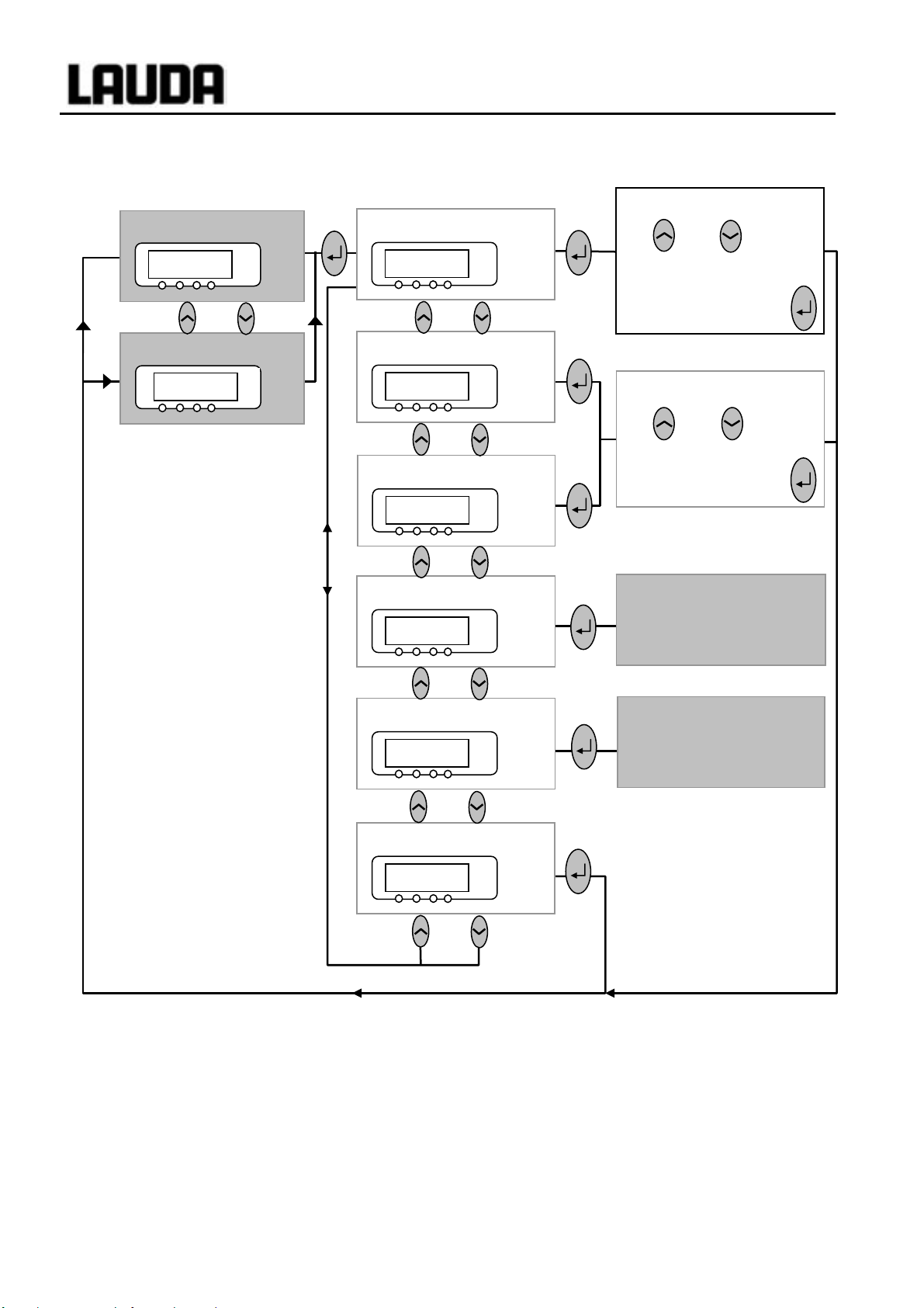
7.6.12 Submenu
LMnet
Æ
B/<P-
Æ
RDp--
(Master): Displaying refrigerating system settings......................51
7.7 IMPORTANT SETTINGS..............................................................................................................................................52
7.7.1 Temperature setpoint setting...........................................................................................................................52
7.7.2 Displaying the actual external temperature....................................................................................................54
7.7.3 Setting pump power or standby.......................................................................................................................55
7.7.4 Activating external control .............................................................................................................................56
7.7.5 Current consumption from the mains..............................................................................................................57
7.7.6 Setting the date and time (Command).............................................................................................................59
7.7.7 Display resolution setting (Command)...........................................................................................................59
7.8 SPECIAL SETTINGS...................................................................................................................................................60
7.8.1 Setpoint resolution..........................................................................................................................................60
7.8.2 Defining the type of start mode.......................................................................................................................60
7.8.3 Defining temperature limits............................................................................................................................62
7.8.4 Setpoint offset operating mode........................................................................................................................63
7.8.5 Restoring works settings.................................................................................................................................65
7.8.6 Setting the volume of the acoustic signals.......................................................................................................67
7.8.7 Entering the offset of the internal temperature probe.....................................................................................68
7.8.8 Restoring the works setting of the internal temperature-probe offset.............................................................69
7.8.9 Entering the offset of the external temperature probe....................................................................................70
7.8.10 Restoring the works setting of the external temperature-probe offset ............................................................71
7.9 GRAPHICAL DISPLAY OF TEMPERATURE MEASUREMENTS (COMMAND)...................................................................72
7.10 PROGRAMMER (PGM ONLY COMMAND).................................................................................................................74
7.10.1 Program example............................................................................................................................................74
7.10.2 Selecting and starting the program (Start, Hold, Stop)..................................................................................76
7.10.3 Interrupting, continuing or terminating the program (Hold, Continue, Stop)................................................77
7.10.4 Creating or modifying a program (Edit).........................................................................................................78
7.10.5 Defining the number of program loops (Loops) .............................................................................................82
7.10.6 Viewing the program sequence as a graph (Graph).......................................................................................82
7.10.7 Obtaining information on a program (Info)....................................................................................................83
7.11 RAMP FUNCTION......................................................................................................................................................84
7.12 TIMER FUNCTION (COMMAND)................................................................................................................................85
7.13 CONTROL PARAMETERS...........................................................................................................................................86
7.13.1 Internal control variable (integral measurement probe)................................................................................87
7.13.2 External control variable (External measurement probe)..............................................................................88
7.14 ALARMS,WARNINGS AND ERRORS .........................................................................................................................91
7.14.1 Overtemperature protection and checking......................................................................................................91
7.14.2 Low-level alarm and low-level checking.........................................................................................................93
7.14.3 High-level settings ..........................................................................................................................................94
7.14.4 High-level warning or alarm..........................................................................................................................95
7.14.5 Pump-motor supervision: Overload or blockage............................................................................................96
7.14.6 Pump-motor supervision: Dry running...........................................................................................................96
7.14.7 Fault list „Alarms and Warnings“..................................................................................................................97
7.15 RS 232 INTERFACE................................................................................................................................................100
7.15.1 Connecting cables and interface test RS 232................................................................................................100
7.15.2 Protocol RS 232............................................................................................................................................100
7.15.3 Connecting cable RS 485..............................................................................................................................101
7.15.4 Protocol RS 485............................................................................................................................................101
7.15.5 Write commands (Data commands to the thermostat)..................................................................................102
7.15.6 Read commands (Data requested from the thermostat)................................................................................103
7.15.7 Error messages.............................................................................................................................................105
7.15.8 Driver software for LABVIEW®...................................................................................................................105
8INTERFACES - MODULES.....................................................................................................................................106
8.1 INSTALLING OF MODULES .....................................................................................................................................106
8.2 MENU STRUCTURE FOR ALL MODULES (ONLY COMMAND)....................................................................................107
8.3 SERIAL INTERFACES RS232 /485 ..........................................................................................................................108
8.3.1 Menu structure for RS232 / 485 Interface Module (Master).........................................................................108
8.4 ANALOGUE MODULE..............................................................................................................................................109

Proline Low-temperature Thermostats
6Contents YACE0072 / 21.08.07
8.4.1 Menu structure Analogue module (Master)..................................................................................................110
8.5 CONTACT MODULE................................................................................................................................................111
8.5.1 Contact module LRZ 915 with three inputs and three outputs .....................................................................111
8.5.2 Namur-Contact module LRZ 914 with only one input and one output.........................................................112
8.5.3 Menu structure contact module (Master).....................................................................................................113
9MAINTENANCE.......................................................................................................................................................114
9.1 CLEANING.............................................................................................................................................................114
9.2 DEVICE STATUS.....................................................................................................................................................114
9.2.1 Interrogating the device type........................................................................................................................114
9.2.2 Software version...........................................................................................................................................114
9.2.3 Serial numbers..............................................................................................................................................114
9.2.4 Device data...................................................................................................................................................115
9.2.5 Fault memory (Command)............................................................................................................................115
9.3 SERVICING REPAIR AND DISPOSAL INFORMATIONS................................................................................................116
9.3.1 Servicing.......................................................................................................................................................116
9.3.2 Repair informations......................................................................................................................................117
9.3.3 Disposal informations ..................................................................................................................................117
9.4 HELP DESK AND ORDERING REPLACEMENT PARTS.................................................................................................118
10 ACCESSORIES......................................................................................................................................................119
11 TECHNICAL DATA .............................................................................................................................................121
12 INDEX.....................................................................................................................................................................125

Proline Low-temperature Thermostats
YACE0072 / 21.08.07 Explanation of signs 7
Explanation of signs:
Danger: This sign is used where there may be injury to
personnel if a recommendation is not followed
accurately or is disregarded.
Note: Here special attention is drawn to some aspect. May
include reference to danger.
Ì
Reference Refers to other information in different sections.

Proline Low-temperature Thermostats
8Safety information YACE0072 / 21.08.07
1 Safety information
1.1 General safety information
A laboratory thermostat heats and circulates liquids according to specified parameters. This involves
hazards due to high temperatures, fire and general hazards due to the application of electrical energy.
The user is largely protected by the application of relevant standards.
Further hazard sources may arise due to the type of tempering medium, e.g. by exceeding or
undercutting certain temperature thresholds or by the breakage of the container and reaction with the
heat carrier liquid.
It is not possible to consider all eventualities. They remain largely subject to the judgment and
responsibility of the operator.
The equipment may only be used as prescribed and as described in these operating instructions. This
includes operation by instructed specialist personnel.
The equipment fulfills the following classes of the EMC standard EN 61326-1:1997 VDE 0843-20:
Class A: Operation only on networks without connected domestic areas.
Class B: Equipment for operation on networks with connected domestic areas.
Class B*: Equipment fulfills Class B when a house connection > 100 A is involved. With unfavorable
network conditions disturbing voltage variations may otherwise occur.
The equipment is not rated for use under medical conditions according to DIN EN 60601-1 or
IEC 601-1.
1.2 Other safety information
•Only connect equipment to PE grounded mains sockets.
•At higher operating temperatures, parts of the bath cover can reach surface temperatures exceeding
70°C. Be careful when touching it ÆRisk of burning!
•Use suitable hoses ÌSection 6.3.
•Secure hose against slippage with the aid of hose clips. Avoid kinks in the hoses.
•Check hoses from time to time for any possible material fatigue.
•Thermal medium hoses and other hot parts must not come into contact with the mains cable.
•With the use of thermostats as circulating thermostats hot liquid can be emitted when the hose
breaks, presenting a hazard to persons and material.
•If no external load is connected, the pump outflow must be closed (use screw plugs) and the bypass
valve must be set to "internal" Ì4.3.
•Take into account the thermal expansion of the heat carrier oils with increasing bath temperature.
•Depending on the heat carrier liquid used and the type of operation, toxic vapors can arise. Ensure
suitable extraction.
•When changing the heat carrier liquid from water to a thermal transfer medium for temperatures
above 100°C, carefully remove all water residues, including from the hoses and loads. When doing
this, also open the blanking caps of the pump outputs and inputs and blow compressed air
through all the pump outputs and inputs. ÆRisk of burning due to delay in boiling!
•Withdraw the mains plug before cleaning, maintenance or moving the thermostat.
•Specialist personnel must only carry out repairs in the control section.
•Figures of temperature constancy and display accuracy apply under normal conditions according to
DIN 12876. Electromagnetic high frequency fields may in special cases lead to unfavorable values.
Safety is not impaired.
•The following action may start the thermostat unintentionally from the standby mode: Previously
activated timer mode Ì7.12, "Start" command via interfaces Ì8.

Proline Low-temperature Thermostats
YACE0072 / 21.08.07 Brief operating instructions 9
2 Brief operating instructions
These brief instructions shall give you the possibility to operate the unit quickly. For safe
operation of the unit, it is necessary to read carefully all the instructions and safety
notes!
1. Assemble unit and add items as appropriate (Ì6.1).
The unit may NEVER be overturned nor put upside down!
Take care of the hose tubing connections (Ì6.3 and 6.4).
2. Fill the unit with corresponding heat carrier liquid (Ì6.3). The units are designed for
operation with non-flammable and flammable liquids to DIN EN 61010-2-010. ÆTake care
of the level of the heat carrier liquid! (Ì6.2).
3. Compare the information on the rating label with the supply details.
4. Connect the unit only to a socket with a protective earth (PE) connection.
5. Check whether the main fuse-switch at the back
is in the "On = –" position.
6. Switch the unit on with the switch at the front.
7. With set the overtemperature cut-off point to a value clearly above room temperature
(Ì7.14.1).
8. Now you see the current bath temperature
in the display, for example:
If instead, a warning or error message is displayed, then refer to Section 7.14.
Bath-temperature
/1%21
°C

Proline Low-temperature Thermostats
10 Brief operating instructions YACE0072 / 21.08.07
2.1 Menu structure: Master
To reset the unit to the factory default state which enables basic operation with internal control, there is
the default function in the menu LMDls ÆO@p@ ÆcDE Ì7.6.4.
Bath temperature
1%21
°C
Pump power.1-8/Standby.0
Os 7
°C
Setpoint
RDr
°C
Control Intern / Extern
Bml 0
°C
Further settings
LMDkt
°C
Configure modules
LMnet
°C
End
Dlc
°C
⇒Section 7.6.2
⇒Section 7.6.3
Display flashes. Set setpoint
with or . Display
is accepted afer 4 sec. or
proceed immediately
with the key:
Control parameters,
setpoint resolution,
setpoint-source input,
calibration, etc.
Protection system,
Command, cooling system,
analog and RS232 digital
module, etc.
External temperature
1%/1
°C
EXT Display flashes. Set value
with or . Display
is accepted afer 4 sec. or
proceed immediately
with the ke
y
:
⇒Section 7.7.3
⇒Section 7.7.4
⇒Section 7.7.1

Proline Low-temperature Thermostats
YACE0072 / 21.08.07 Brief operating instructions 11
2.2 Menu structure: Command
Menu
Display
Sounds Master
Sounds Command
Language
Master-Mode
Autostart
Current Consumpt.
Pump
Settings
Clock
Graph
Programmer
Interfaces 1
Control
Limits
Pump Level
Calibration
Works settings
Resolution
Device status
Display data
Basic settings
Overlevel handling
Set time
Set data
Timer 1
Timer 2
Format of date
Program 1
Program 2
Program 3
Program 4
Program 5
Ramp function
Serial Command
2serial Master /
Profibus
Analog interfaces
Switching contact
Refill valve
Shut off unit
Smart Cool
Control parameters
Control para. sets
Tv manual/auto
Correction limitation
Control variable
Control parameters
Setpoint offset
Brightness
Contrast
intern Pt100
extern Pt100
Device type
Software Version
Serial numbers
Device data
Error store
Mode
Baud rate
RS485 address
internal
external Pt100
Analog interface
RS232/485
Calibration
Default
Alarm
Warning
all default
Basic window
Standard window
Super window
Edit
Default
T il (min)
T ih (max)
Xp
Tn
Tv (auto)
Td (auto)
Kpe
Tne
Tve (auto)
Tde (auto)
Xpf
Prop_E(a)
off
external Pt100
RS 232
Status
Edit
Loops
Graph
Info
Start / Stop
Hold / continue
Modify
Erase
Show chart
Offset source
Setpoint offset
Automatic
Manual
All Modules
Master
Command
Cool
Other connected
modules
English
Deutsch
Français
Español
All default
Only control par. int.
Only control par. ext.
Only miscellaneous
Display
Settings
Mode
Displayed value
Legend
Sample Time
Time axis
Time base
Temp. scale
Temp. limits
off
on
automatic
none
Warning
Warn. + Heater off
Alarm
Status
Temp. Change
Time
Time unit
1ÌCapter 8
2no menu in
Command
on
off
on

Proline Low-temperature Thermostats
12 Controls and functional elements YACE0072 / 21.08.07
3 Controls and functional elements
Mobile Command Console
(
see
p
a
g
e 14
)
Master control panel (see page 14)
Mains switch
Pump connection at side:
Suct
i
o
n n
o
zzl
e
(
r
etu
rn
to
bat
h
)
Bypass valve (see illustration on next page)
Side pump connection:
Pump outflow, pressure output
Bath cover
Recessed grip
Grille (on both sides)
Front cover (closed)
Transport rollers (concealed)
Feet (concealed)
Front cover (open)
Bath drain tap
Bath drain nozzle
Condenser

Proline Low-temperature Thermostats
YACE0072 / 21.08.07 Controls and functional elements 13
Mobile Command Console (see next page)
Covers for the two module slots
Connection socket 10S
for the external Pt1
00
tem
p
erature
p
robe
Connection socket 70S (LAUDA internal bus
(LiBus)) for bus suitable for unit and to which
the refrigerating lower section, the integrated
electricall
y
heated cover
p
late and Command
Main fuse-switch
Connection socket 51H for refrigerating lower
section
Mains connecting lead
Air intake for electronic head
Rear pump connection:
Suction nozzle (return to bath)
Rear pump connection:
Pump outflow, pressure output
Transport handle
Rear grid
Bypass valve
(in "external" position)
Side pump connection:
Pump outflow, pressure output
(closed off with screw plug)
Side pump connection:
Suction nozzle (return to bath)
(closed off with screw plug)

Proline Low-temperature Thermostats
14 Controls and functional elements YACE0072 / 21.08.07
Control element: Master
Control element: Command
Error signal (red LED blinking)
Bath controlled by external
temperature source (geen LED
lits)
The temperature of an external
source is displayed
(EXT is lit green)
Cooler active (blue LED is lit)
Overtemperature set point to
check or set Tmax
Select and Enter keys
Graphical display,
here in the standard window displaying the values:
•Actual temperature Tint of internal bath temperature probe
•Setpoint temperature Tset
•Actual temperature Text of the external temperature probe
•Bath level
•Pum
p
level
5 soft-key duo-keys – their
associated functions are
shown in the display.
Enter key
Cursor key
Decimal point or "-" symbol
Standby key,
brings the thermostat into
the idle mode. Heater,
Escape key to quit a
window without any
EXT
Heater active (yellow LED is lit)
Mains On
(green LED is lit)
RS 232-socket
(hidden on the back Command )
Yellow Stand-By LED

Proline Low-temperature Thermostats
YACE0072 / 21.08.07 Unit description 15
4 Unit description
4.1 Environmental conditions
The operation of the thermostats is only allowed under the following conditions as specified in
DIN EN 61010-2-010:2003 and DIN EN 61010-1:2001:
−Indoor use.
−Altitude up to 2000 m above sea level.
−Foundation must be dense, even, non-slippery and non-flammable.
−Keep clear distance Ì6.1 Assembly and siting.
−Ambient temperatures range Ì11 Technical data.
Use only within this range for an undisturbed operation.
−Mains supply voltage fluctuations Ì11 Technical data.
−Relative
humidity Ì11 Technical data.
−Transient over voltage according to Installation Categories (Over voltage Categories) II.
−Pollution degree: 2.
4.2 Types of unit
The type designation of the Proline Low-Temperature Thermostats comprises the prefix R (to
designate the refrigeration machine), a P for Proline, the bath volume in liters and the lowest bath
temperature (guide figure without arithmetic sign).
Units in Command version are marked with a “C” at the end of the model description.
Examples: RP 855 is a low-temperature thermostat with 8-liter bath and -55 °C min. temperature.
RP 1845 is a low-temperature thermostat with 18-liter bath and -45 °C min. temperature.
4.3 VarioFlex pump
All units are fitted with a VarioFlex pump with an 8-stage variable drive. The pump power can
therefore be optimally matched to the relevant task: High pump pressure when, for example, long
hoses pass to external loads or circulation is to be provided for a large bath. Low pressure when the
heat input into the bath must be low.
As a delivery/ suction pump, the VarioFlex pump enables the very effective supply of pressure-
sensitive glass reactors, which have a minimum permissible pressure rating.
Furthermore, open vessels can be operated when a constant level controller (accessory LCZ 0660) is
used.
At the right-hand side and at the back of the unit outflow and inflow nozzles are fitted for external
loads. This means that up to two external loads can be directly connected without a distributor.
Connections, which are not required, must be closed off with the supplied caps and union nuts.
A bypass valve can subdivide the total volume flow variably between the bath (internally) and the
connected load (externally). Consequently, no "pump short circuit" is needed. If no load is connected
to the pump connector, the bypass valve must be set to the “internal” position for the best bath
circulation.
In the heating range, the VarioFlex pump operates up to viscosity values of 150 mm²/s. In the closed-
loop control mode 50 mm²/s should not be exceeded. The temperature control is the best with
30 mm²/s and lower viscosity.
With small bath coolers (e.g. RP 845) power level 1 to 3 is practicable.

Proline Low-temperature Thermostats
16 Unit description YACE0072 / 21.08.07
For operation as a circulating thermostat with an external load, a higher power level is practicable to
maintain the temperature difference low, among other things also with higher temperatures in
conjunction with oils as heat carrier liquid.
The pump connections on the unit are fitted with M16 x 1 thread.
The pump outflows of the VarioFlex pump can be closed off without any impairment to the pump.
Here, the "internal" setting of the bypass controller is recommended.
Pump characteristics (ÌSection 11).
4.4 Materials
All parts being exposed to the heat carrier liquid are made of high quality material appropriate to the
operating temperature. Non-rusting stainless steel and high quality temperature-resistant, primarily
solvent-resistant plastics are used.
4.5 Temperature display, control and safety circuit
In the Master Version, the units are equipped with a 5-character green LED display, which is used for the
display of the measurements and settings, as well as the operating status. The entry of setpoints and
other settings occurs under menu guidance via four keys.
The extra features of the Command Version include a removable console with a backlit graphical
display. The entry of the setpoint and other settings occurs under menu guidance via situation-
dependent cursor keys and soft keys.
A Pt100 temperature probe acquires the outflow temperature in the bath. A high-resolution A/D converter
processes the measurement. Further measurement conditioning occurs using a special control algorithm
for controlling the heater actuator, which has a low reactive effect on the mains, and the SmartCool
refrigeration equipment together with further transducers.
An external Pt100 can be connected via a socket (10S) for the acquisition of an external temperature.
This value can be displayed and, if required, used as the controlled variable with external control
(Master) switched on. In this way, the system controls the external measurement and not the outflow
temperature Ì7.7.4.
The safety system conforms to DIN EN 61010-2-010. The SelfCheck Assistant monitors about 50 unit
parameters. A dual-channel system is used in which two microcontrollers monitor one another. Along
with the bath temperature measurement and control probes, there are also two safety temperature
probes (Pt100) for the safety circuit for the overtemperature cut-off and for monitoring the bath
temperature probe.
The overtemperature cut-off point is displayed on pressing the key on the Master.
Changing the overtemperature cut-off point: Ì7.2 (Switching on) on page 25.
The bath level is acquired by the SelfCheck Assistant in 8 stages. A permanent display is provided only
with the Command Version. At the Master version, it is showed in the submenu RgmY[ . If the minimum
level is undercut, the pump, heater and the SmartCool System refrigerating machine are switched off.
The reaction of the thermostat in case of overfill can be set to simply display a warning, to display a
warning and switch off the heater or to switch off the unit completely with pump, heater and SmartCool
System refrigerating machine.
When the level is too low, with overtemperature, or with other alarms the SelfCheck Assistant switches
the heater off on all poles. The pump and the refrigerating machine are also switched off.
This switch-off under fault conditions is retained, i.e. after the fault is rectified, the fault must be reset

Proline Low-temperature Thermostats
YACE0072 / 21.08.07 Unit description 17
(released) on the Master operating panel with the key.
Other unit functions are described in the appropriate sections and in Section 7. (Starting up).
4.6 Programmer and ramp function
Master Version:
No programmer provided.
Command Version:
The units are equipped with a programmer function, which enables five temperature/time programs to
be saved. Each program consists of a number of temperature/time segments. These also include details
of how often the program is to be executed. Up to 150 segments can be distributed amongst the five
programs.
With the ramp function, a rate of change can be directly entered in °C/ unit time. (Ì7.10).
4.7 Interfaces
Master Version:
In the basic version, the Master unit is equipped with the following sockets at the back of the control
head:
•For the connection of an external Pt100 temperature sensor (10S).
•Two sockets (70S) for the connection of components via the LAUDA equipment bus (cooling
section, Command Console, external solenoid valve, etc.).
Command Version:
The Command unit is equipped as standard with the following sockets:
•For the connection of an external Pt100 temperature probe (10S).
•Two sockets (70S) for the connection of components via the LAUDA equipment bus (cooling
section, Command Console, external solenoid valve, etc.)
•An RS232 / RS485 interface (65S) at the back of the Command Console.
4.8 Interface modules (accessories)
The Master and Command can be supplemented with further interface modules, which are simply
inserted into two module slots (see Section 3) at the back of the control head.
The following modules are currently available :
1. RS232 / 485 Interface Module (Order No. LRZ 913) with 9-pole SUB-D socket. Electrically
isolated through optocouplers. Command set largely compatible with the Ecoline, Integral XT and
Integral T Series. The RS2323 interface can be directly connected to the PC with a cable wired
1:1 straight through (Order No. EKS 037).
Further details can be found in section 8.3.
2. Analog Module (Order No. LRZ 912) with two inputs and two outputs on 6-pole DIN socket. The
inputs and outputs can be set independently as 4...20 mA, 0...20 mA or 0...10 V interface.

Proline Low-temperature Thermostats
18 Unit description YACE0072 / 21.08.07
Further details can be found in section 8.4.
3. Contact Module (Order No. LRZ 915) on 15-pole SUB-D socket. With three relay contact outputs
(changeover, max. 30V/ 0.2A) and three binary inputs for control via external voltage-free
contacts. Plug 15-pole, Order No. EQM 030 and plug case Order No. EQG 017.
Further details can be found in section 8.5.
4. Contact Module (Order No. LRZ 914) with connector to NAMUR NE28. Functionality as
LRZ 915, but only one output and one input on each of two DIN sockets. Coupling socket 3-pole,
LAUDA Order No. EQD 047 and coupling plug 3-pole, LAUDA Order No. EQS 048.
Further details can be found in section 8.5.
5. Profibus
Modules (Order No. LRZ 917).
Further details can be found in the operating instructions of the Profibus Modules YAAE0020.
4.9 Cooling unit
The refrigerating machine mainly consists of one or two fully hermetically sealed compressors. The
heat from the condensation process and the motor is dissipated via a lamellar condenser. Here, fresh
air is drawn in at the front of the unit, heated towards the back and output at the side. To ensure proper
air circulation the ventilation slots must not be restricted. See Section 6.1.
The coolers of the Proline Series are equipped with the SmartCool technology which makes optimum
use of the compressor and only then cools when refrigerating capacity is demanded by the controller.
To achieve this, a number of sensors in the cooling circuit monitor the operating conditions.
The compressors are equipped with overtemperature cutouts, which respond to the compressor
temperature and the compressor current consumption. In addition, the refrigeration system is backed
up by a pressure control device against over pressure. The cooling unit is normally switched in
automatically, but can be switched manually via the operating menu. (ÌSection 7.6 with Command
und 7.6.3 with Master).
When the fault circuit trips, the cooling unit is also switched off.
Cooling curves (ÌSection 11).
4.10 Avoidance of dewing
In order to avoid dewing on the edge of the bath when using the low temperature thermostats RP 855,
RP 870, RP 890 and RP 1290, these instruments are equipped with a device for heating the edge of
the bath, using the waste heat of the cooling unit.
As a standard feature, the minimum temperature thermostats RP 890 and RP 1290 are equipped with
an additional electric heating of the bath bridge. This can be ordered as an option for RP 855 and
RP 870.
With the bath covers of the minimum temperature thermostats, RP 890 and RP 1290, it is possible, by
means of a nipple, to let nitrogen or dry air into the bath with a low volume flow.
4.11 Heater rating and power consumption from the mains
The Proline Low-Temperature Thermostats have an extraordinarily high heater rating of 3.5 kW
maximum. If your mains fuse is rated below 16A, the current consumption can be reduced in steps
from 16 A to 10 A Ì7.7.5. The maximum heater rating of 3.5 kW is then, of course, also reduced
accordingly.

Proline Low-temperature Thermostats
YACE0072/ 21.08.07 Unpacking 19
5 Unpacking
After unpacking, firstly check the device and accessories for any damage in transit. If, contrary to
expectations, there is visible damage to the unit, the shippers or the postal service must be
immediately informed, so that an investigation can be made. Please also inform the LAUDA Service
Centre (Contact Ì9.4.).
Standard Accessories:
Article number Quantity Article
YACE0072 1 Operating instructions (this document) for all cooling thermostats
HDQ 108 1 Bath cover at RP 845, RP 855 and RP 870
HDQ 109 1 Bath cover at RP 1840, RP 1845 and RP 3530
LCZ 9671 1 Bath cover for bath bridge heating at RP 890 and RP 1290
HKO 026
(UD 413) 2 Hose olive Ø 13mm for all cooling thermostats
HKM 032 4 Union nuts for olives (M16x1) for all cooling thermostats
HKN 065 4 Screw plugs (for M16x1) for all cooling thermostats
EKS 073 1 T-piece adaptor cable for the internal
LAUDA device bus (LiBus) with Command cooling thermostats
only
EZB 260 1 Warning label "Hot" for all cooling thermostats

Proline Low-temperature Thermostats
20 Preparation YACE0072 / 21.08.07
6 Preparation
6.1 Assembly and siting
−Site the unit on a flat surface
−The unit must not be put into operation if its
temperature during storage or transport has dropped
below the dew point.
Wait for about one hour.
−The unit may NEVER be overturned nor put upside
down!
−Do not cover the ventilation openings at the back of
the control head and on all sides of the lower section
of the unit.
−Leave at least 40 cm of free space on all sides.
−For operation as bath thermostat, set the bypass valve
to internal (without external loads) (ÌSection 3).
−Plug the (high resistance) connector into the
corresponding socket 51H on the back of the control
head, the Bus-cable into the plug 70S and secure
both.
−Only RP 890 and RP 1290: In case of disturbing
dewing, connect the heating of the bath bridge. Plug
the supplied T-piece adaptor cable for the LAUDA
device bus into the 70S socket and secure it. Connect
it with the connection cable of the bath bridge heating.
−Plug the bus connector of the Command console also
into the 70S socket or into the T-piece and secure it.
−Further T-adaptors are available as accessories
EKS 073.
−Avoid condensation of air humidity: Connect nitrogen
or dry air with a low volume flow for superposition to
the nipples of the bath covers of the minimum
temperature thermostats RP 890 and RP 1290.
Operation with external loads
(Circulating thermostat) continue at ÌSection 6.4.
−Check whether the pump connectors at the side and back are fitted with sealing
caps (ÌSection 3) or that hoses are fitted for external loads.
−With bath temperatures over 70°C the supplied self-adhesive label
should be applied on the bath at an easily visible point.
−Do not carry out technical changes on the device!
In particular, it is not allowed to bore into the edges of the bath!
−The unit can be safely operated up to an ambient temperature of 40°C.
−An increased ambient temperature reduces the cooling capacity.
This manual suits for next models
7
Table of contents
Other Lauda Thermostat manuals

Lauda
Lauda IN 130 T User manual

Lauda
Lauda RP 4050 C User manual

Lauda
Lauda Viscotemp 15 G User manual

Lauda
Lauda PROLINE P 5 C User manual

Lauda
Lauda P 10 User manual

Lauda
Lauda Ecoline RE 320 User manual

Lauda
Lauda PROLINE Kryomats Series User manual

Lauda
Lauda IN 550 XT User manual

Lauda
Lauda RCS 5 User manual

Lauda
Lauda RP 3050 C User manual

Lauda
Lauda PROLINE P 5 C User manual

Lauda
Lauda RE 1050 G User manual

Lauda
Lauda LOOP 100 User manual

Lauda
Lauda RE 212 J User manual

Lauda
Lauda Ecoline RE 204 User manual

Lauda
Lauda Integral T 1200 User manual

Lauda
Lauda E 4 G User manual

Lauda
Lauda P 10 User manual

Lauda
Lauda Alpha User manual

Lauda
Lauda ECO GOLD User manual