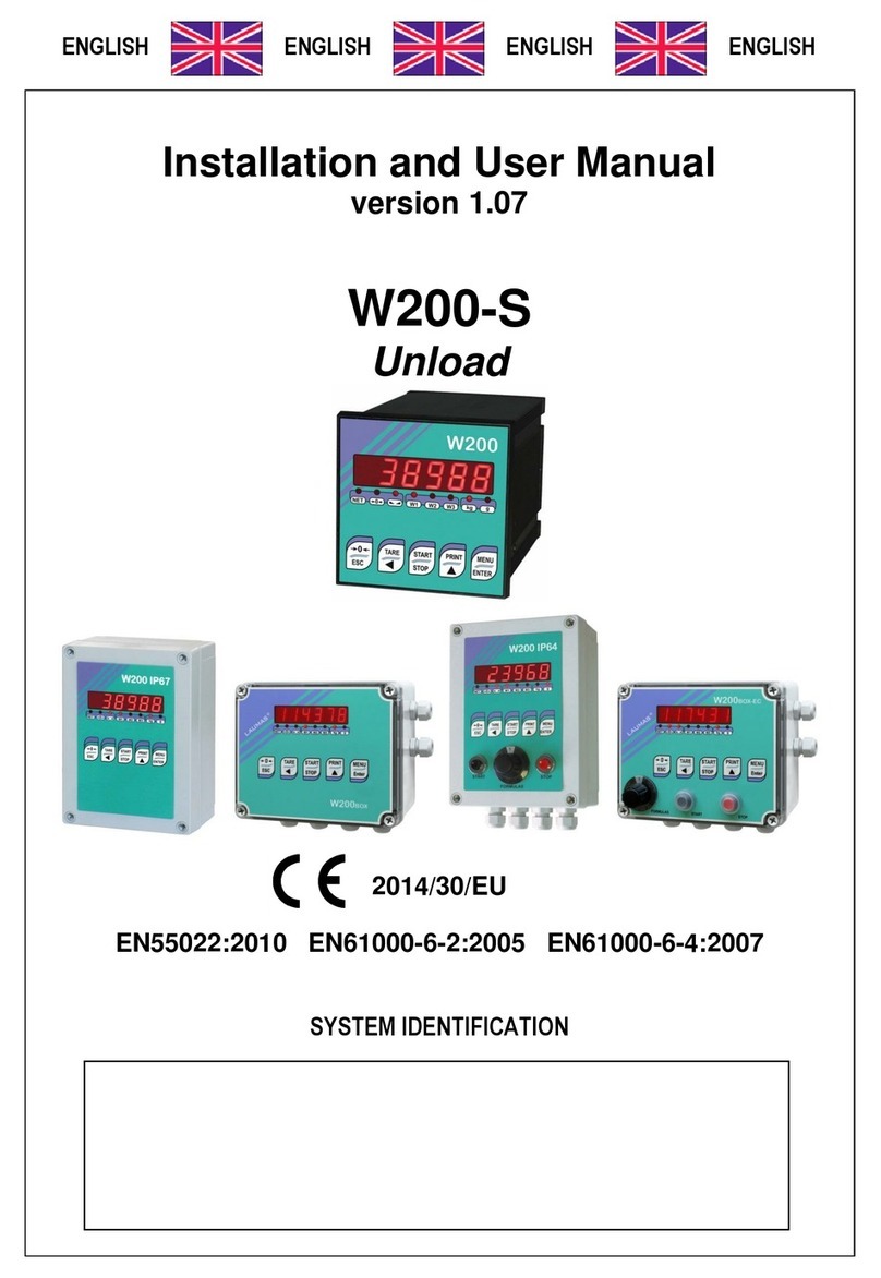
LAUMAS ADPEW200 User manual

ENGLISH ENGLISH ENGLISH ENGLISH
Installation and User Manual
version 1.00
ADPEW200
In ADPE explosion proof box

GUARANTEE
24 months from the delivery document date. The guarantee covers only defected parts and includes the replacement
parts and labour. All shipping and packing costs are paid by the customer. It is possible to have the repair in
guarantee on condition that the returned product has not been transformed, damaged or repaired without
authorization. No guarantee is applicable on returned products without the original label and/or serial number. No
guarantee against misuse.
Batteries: Laumas provides 1 year guarantee from the date of delivery note, against material defects or battery
manufacturing faults.
DISPOSAL
This symbol on the product or on the packaging indicates that:
- This is an electrical/electronic device that should be disposed of separately from the municipal solid waste via
designated collection facilities
- Improper use or disposal can be harmful to human health and the environment
- Non-compliance with these guidelines will be sanctioned according to the laws in force in the destination country
- It is recommended to dispose of packaging in accordance with local regulations

USER WARNINGS
RECOMMENDATIONS FOR THE PROPER USE OF WEIGHING INSTRUMENT
- Keep away from heat sources and direct sunlight
- Repair the instrument from rain (except special IP versions)
- Do not wash with water jets (except special IP versions)
- Do not dip in water
- Do not spill liquid on the instrument
- Do not use solvents to clean the instrument
- Do not install in areas subject to explosion hazard (except special Atex versions)
RECOMMENDATIONS FOR CORRECT INSTALLATION OF WEIGHING INSTRUMENTS
The terminals indicated on the instrument’s wiring diagram to be connected to earth must
have the same potential as the weighed structure (same earthing pit or earthing system). If
you are unable to ensure this condition, connect with an earthing wire the terminals of the
instrument (including the terminal – SUPPLY) to the weighed structure.
The cell cable must be individually led to its panel input and not share a conduit with other cables;
connect it directly to the instrument terminal strip without breaking its route with support terminal strips.
Use “RC” filters on the instrument-driven solenoid valve and remote control switch coils.
Avoid inverters in the instrument panel; if inevitable, use special filters for the inverters and separate
them with sheet metal partitions.
The panel installer must provide electric protections for the instruments (fuses, door lock switch etc.).
It is advisable to leave the equipment always switched on to prevent the formation of condensation.
MAXIMUM CABLE LENGTHS
- RS485: 1000 metres with AWG24, shielded and twisted cables
- RS232: 15 metres for baud rates up to 19200
- Analog current output: up to 500 metres with 0.5 mm2 cable
- Analog voltage output: up to 300 metres with 0.5 mm2cable

RECOMMENDATIONS FOR CORRECT INSTALLATION OF THE LOAD CELLS
INSTALLING LOAD CELLS
The load cells must be placed on rigid, stable in-line structures; it is important to use the mounting
modules for load cells to compensate for misalignment of the support surfaces.
CONNECTING SEVERAL CELLS IN PARALLEL
Connect several cells in parallel by using - if necessary - a watertight junction box with terminal box.
The cell connection extension cables must be shielded, led individually into their piping or conduit
and laid as far as possible from the power cables (in case of 4-wire connections, use cables with
4x1 mm2minimum cross-section).
PROTECTION OF THE CELL CABLE
Use water-proof sheaths and joints in order to protect the cables of the cells.
MECHANICAL RESTRAINTS (pipes, etc.)
When pipes are present, we recommend the use of hoses and flexible couplings with open
mouthpieces with rubber protection; in case of hard pipes, place the pipe support or anchor bracket as
far as possible from the weighed structure (at a distance at least 40 times the diameter of the pipe).
WELDING
Avoid welding with the load cells already installed. If this cannot be avoided, place the welder ground
clamp close to the required welding point to prevent sending current through the load cell body.
WINDY CONDITIONS - KNOCKS – VIBRATIONS
The use of weigh modules is strongly recommended for all load cells to compensate for
misalignment of the support surfaces. The system designer must ensure that the plant is protected
against lateral shifting and tipping relating to: shocks and vibration; windy conditions; seismic
conditions in the installation setting; stability of the support structure.

EARTHING THE WEIGHED STRUCTURE
By means of a copper wire with suitable cross-section, connect the cell upper support plate with the
lower support plate, then connect all the lower plates to a single earthing system. Electrostatic
charges accumulated because of the product rubbing against the pipes and the weighed container
walls are discharged to the ground without going through or damaging the load cells. Failure to
implement a proper earthing system might not affect the operation of the weighing system; this,
however, does not rule out the possibility that the cells and connected instrument may become
damaged in the future. It is forbidden to ensure earthing system continuity by using metal parts
contained in the weighed structure.
FAILURE TO FOLLOW THE INSTALLATION RECOMMENDATIONS WILL BE CONSIDERED
A MISUSE OF THE EQUIPMENT

- 1 -
THE SYSTEM IS COMPOSED OF:
W200 weight indicator, provided in one of the following models: W200 BASE, W200 LOAD,
W200 UNLOAD, W200 MULTI, W200 3-6-14 PRODUCTS (see enclosed manual).
WARNING: ADPEW200 is not compatible with NTEP approved instruments.
ATEX [EEx ia] certified barriers (dimensions: 105x12,6x82 mm, mounting on standard
OMEGA/DIN rail):
- MTL 7766Pac supply barrier:
-20 °C≤Ta≤+60 °C; Uo=12 V; lo=314 mA; Po=0.942 W; Co=1.41 μF; Lo=0.34 mH; Lo/Ro =
37 mΩ/Ω(two channels in parallel)
- MTL 7761ac signal barrier:
-20 °C≤Ta≤+60 °C; Uo=9 V; lo=100 mA; Po=0.225 W; Co=4.9 μF; Lo=3.72 mH; Lo/Ro =
158 mΩ/Ω(for each channel)
ATEX marking
II (1) GD
[Ex ia Ga] IIC
[Ex ia Da] IIIC
(-20 °C≤Ta≤+60 °C)
BAS01ATEX7217
IECEx marking
[Ex ia Ga] IIB
[Ex ia Ga] IIC
[Ex ia Da] IIIC
(-20 °C≤Ta≤+60 °C)
IECEx BAS 04.0025
ADPE explosion proof box equipped with a
transparent window and 5 external buttons which
performs the same function as W200 keypad:
ATEX marking
II 2(1) GD
Ex d [ia Ga] IIB+H2 T6 Gb
Ex tb [ia Da] IIIC T85°C Db IP66
(-20 °C≤Ta≤+40 °C)
INERIS 14ATEX0008X
IECEx marking
Ex d [ia Ga] IIB+H2 T6 Gb
Ex tb [ia Da] IIIC T85°C Db IP66
(-20 °C≤Ta≤+40 °C)
IECEx INE 13.0065X
230
255
REAR SIDE
180
4x Ø9
54.5 60
55 55
55
310
250
262
BOTTOM SIDE
5x 3/4'' NPT
174
230

- 2 -
ELECTRICAL CONNECTIONS
Warning! For electrical connections and power supply of the instrument refer to the wiring diagram
of the specific instrument manual.
19
1
13
23456
16
14 15 17 18
12
24
7811
109
21
20 22 23
EX -
LOAD CELLS
SIG +
EX +
SIG -
REF -
REF +
6-WIRE load cell
CONNECTION
12 12
3434
SIG -
SIG +
EX+
EX -
7766Pac
7761ac
EX+
EX-
SIG + SIG -
REF -
REF +
REF+
REF-
Shield
Load
cells
SAFE
AREA
HAZARDOUS
AREA
INSTALLER'S
RESPONSIBILITY
WARNING! For the electrical connections and
power supply of the instrument refer to the
wiring diagram of the specific instrument
manual

- 3 -
ELECTRICAL CONNECTIONS BETWEEN LOAD CELLS AND JUNCTION BOX
Connect the load cells by means of a terminal board housed inside an ATEX certified junction box,
connecting together wires of the same colour; the same procedure applies to the shields, keeping
them separate from the earthing system and connected metal parts. By means of a shielded
extension cable, connect the junction box to the barriers mounted inside the explosion proof box.

- 4 -
DECLARATION OF CONFORMITY - EU
SISTEMIDIPESATURAINDUSTRIALE‐CELLEDICARICO‐BILANCE
LAUMASElettronicaS.r.l.
ViaIMaggio6‐43022Montechiarugolo(PR)Italy
C.F.‐P.IVAIT01661140341
Tel.(+39)0521683124
Fax(+39)0521681091
Email:[email protected]
Web:http://www.laumas.com
FabbricantemetricoProt.N.7340Parma‐R.E.A.PRN.169833‐Reg.ImpresePRN.19393‐RegistroNazionalePile
N.IT09060P00000982‐RegistroA.E.E.N.IT08020000002494‐N.Mecc.PR008385‐Cap.Sociale€100.000int.vers.
SISTEMAQUALITÀCERTIFICATOUNIENISO9001‐SISTEMAGESTIONEAMBIENTALEISO14001‐MODULOD:GARANZIADELLAQUALITÀDELPROCESSODIPRODUZIONE
I Dichiarazione di
conformità
Dichiariamo che il prodotto al quale la presente dichiarazione si riferisce è conforme alle norme di
seguito citate.
GB Declaration of
conformity
We hereby declare that the product to which this declaration refers conforms with the following
standards.
E Declaración de
conformidad
Manifestamos en la presente que el producto al que se refiere esta declaración está de acuerdo con
las siguientes normas
D Konformitäts-erklärung Wir erklären hiermit, dass das Produkt, auf das sich diese Erklärung bezieht, mit den nachstehenden
Normen übereinstimmt.
F Déclaration de
conformité
Nous déclarons avec cela responsabilité que le produit, auquel se rapporte la présente déclaration, est
conforme aux normes citées ci-après.
CZ Prohlášení o shode Tímto prohlašujeme, že výrobek, kterého se toto prohlášení týká, je v souladu s níže uvedenými
normami.
NL Conformiteit-verklaring Wij verklaren hiermede dat het product, waarop deze verklaring betrekking heeft, met de hierna
vermelde normen overeenstemt.
P Declaração de
conformidade
Declaramos por meio da presente que o produto no qual se refere esta declaração, corresponde às
normas seguintes.
PL Deklaracja zgodności Niniejszym oświadczamy, że produkt, którego niniejsze oświadczenie dotyczy, jest zgodny z
poniższymi normami.
RUS Заявление о
соответствии
Мы заявляем, что продукт, к которому относится данная декларация, соответствует
перечисленным ниже нормам.
Models: ADPEW200
Mark Applied EU Directive Standards
2014/35/EU
Low Voltage Directive
Not Applicable (N/A) for VDC type
EN 61010-1:2010+A1:2019
for 230/115 VAC type
2014/30/EU
EMC Directive
EN 55011:2016+A1+A11:2020
EN 61000-6-2:2019
EN 61000-6-4:2019
EN 61000-4-2:2009
EN 61000-4-3:2006+A2:2010
EN 61000-4-4:2012
EN 61000-4-5:2014+A1:2017
EN 61000-4-6:2014
M
(only if “M” mark is applied)
2014/31/EU
NAWI Directive
EN 45501:2015
OIML R76-1:2006
Montechiarugolo (PR), 18/11/2022 LAUMAS Elettronica s.r.l.
M. Consonni
(Legal Representative)

- 5 -
DECLARATION OF CONFORMITY - UKCA
SISTEMIDIPESATURAINDUSTRIALE‐CELLEDICARICO‐BILANCE
LAUMASElettronicaS.r.l.
ViaIMaggio6‐43022Montechiarugolo(PR)Italy
C.F.‐P.IVAIT01661140341
Tel.(+39)0521683124
Fax(+39)0521681091
Email:[email protected]
Web:http://www.laumas.com
FabbricantemetricoProt.N.7340Parma‐R.E.A.PRN.169833‐Reg.ImpresePRN.19393‐RegistroNazionalePile
N.IT09060P00000982‐RegistroA.E.E.N.IT08020000002494‐N.Mecc.PR008385‐Cap.Sociale€100.000int.vers.
SISTEMAQUALITÀCERTIFICATOUNIENISO9001‐SISTEMAGESTIONEAMBIENTALEISO14001‐MODULOD:GARANZIADELLAQUALITÀDELPROCESSODIPRODUZIONE
I Dichiarazione di
conformità
Dichiariamo che il prodotto al quale la presente dichiarazione si riferisce è conforme alle norme di
seguito citate.
GB Declaration of
conformity
We hereby declare that the product to which this declaration refers conforms with the following
standards.
E Declaración de
conformidad
Manifestamos en la presente que el producto al que se refiere esta declaración está de acuerdo con
las siguientes normas
D Konformitäts-erklärung Wir erklären hiermit, dass das Produkt, auf das sich diese Erklärung bezieht, mit den nachstehenden
Normen übereinstimmt.
F Déclaration de
conformité
Nous déclarons avec cela responsabilité que le produit, auquel se rapporte la présente déclaration, est
conforme aux normes citées ci-après.
CZ Prohlášení o shode Tímto prohlašujeme, že výrobek, kterého se toto prohlášení týká, je v souladu s níže uvedenými
normami.
NL Conformiteit-verklaring Wij verklaren hiermede dat het product, waarop deze verklaring betrekking heeft, met de hierna
vermelde normen overeenstemt.
P Declaração de
conformidade
Declaramos por meio da presente que o produto no qual se refere esta declaração, corresponde às
normas seguintes.
PL Deklaracja zgodności Niniejszym oświadczamy, że produkt, którego niniejsze oświadczenie dotyczy, jest zgodny z
poniższymi normami.
RUS Заявление о
соответствии
Мы заявляем, что продукт, к которому относится данная декларация, соответствует
перечисленным ниже нормам.
Models: ADPEW200
Mark Applied UK legislation Standards
Electrical Equipment
(Safety) Regulations 2016
Not Applicable (N/A) for VDC type
BS EN 61010-1:2010+A1:2019
for 230/115 VAC type
Electromagnetic
Compatibility
Regulations 2016
BS EN 55011:2016+A1+A11:2020
BS EN 61000-6-2:2019
BS EN 61000-6-4:2019
BS EN 61000-4-2:2009
BS EN 61000-4-3:2006+A2:2010
BS EN 61000-4-4:2012
BS EN 61000-4-5:2014+A1:2017
BS EN 61000-4-6:2014
(only if “M” mark is applied)
Non-automatic Weighing
Instruments Regulations
2016
BS EN 45501:2015
Montechiarugolo (PR), 18/11/2022 LAUMAS Elettronica s.r.l.
M. Consonni
(Legal Representative)


On our website www.laumas.com you can find videos on the correct installation of weighing
systems and tutorials on the configuration of our weight transmitters and indicators.
Comprehensive user manuals for all LAUMAS products can be found online. They can be
downloaded in PDF format from either the Products section or the Download Area of the
website www.laumas.com. Registration is required.
Think of the environment before you print!
CERTIFICATION OF THE ENVIRONMENTAL MANAGEMENT SYSTEM
according to UNI EN ISO 14001.
LAUMAS contributes to safeguarding the environment by saving on paper consumption.
Table of contents
Other LAUMAS Measuring Instrument manuals
Popular Measuring Instrument manuals by other brands

SIGRIST
SIGRIST StackGuard instruction manual

Bosch
Bosch GMS 120 Professional Original instructions

Ecolab
Ecolab Nalco Water STORM Settling Rate Monitor Installation, operation & maintenance manual

Endress+Hauser
Endress+Hauser Proline Prowirl D 200 Brief operating instructions

HT Italia
HT Italia HT14D user manual

ThermoWorks
ThermoWorks Classic Thermapen operating instructions