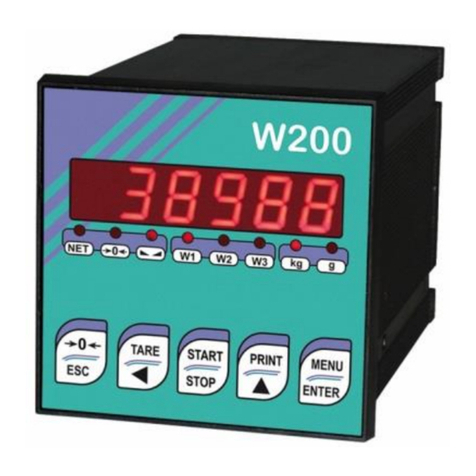
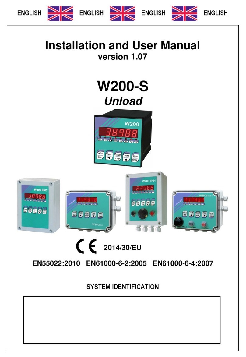
LAUMAS W200-MU User manual

Installation and User Manual
version 1.08
W200
Base
2014/30/EU
EN55022:2010 EN61000-6-2:2005 EN61000-6-4:2007
SYSTEM IDENTIFICATION
Microlectra bv. www.microlectra.nl [email protected]
Microlectra bv.
Augustapolder 12. 2992 SR Barendrecht. The Netherlands.
www.microlectra.nl [email protected]

KEY TO SYMBOLS
Below are the symbols used in the manual to draw the reader's attention:
Warning! Risk of electrocution.
Warning! This operation must be performed by skilled workers.
Read the following indications carefully.
Further information.
GUARANTEE
24 months from the delivery document date. The guarantee covers only defected parts and includes the replacement parts and
labour. All shipping and packing costs are paid by the customer. It is possible to have the repair in guarantee on condition that the
returned product has not been transformed, damaged or repaired without authorization. No guarantee is applicable on returned
products without the original label and/or serial number. No guarantee against misuse.
Batteries: Laumas provides 1 year guarantee from the date of delivery note, against material defects or battery manufacturing faults.
Disposal of Waste Equipment by Users in Private Households in the European Union
This symbol on the product or on its packaging indicates that this product must not be disposed of with
your other household waste. It is your responsibility to dispose of your waste equipment by handing it
over to a designated collection point for the recycling of waste electrical and electronic equipment. The
separate collection and recycling of your waste equipment at the time of disposal will help preserve
natural resources and protect human health and the environment. For more information about where you
can drop off your waste equipment for recycling, please contact your local waste disposal Authority or
the equipment retailer.

TABLE OF CONTENTS
USER WARNINGS................................................................................................................. 1
RECOMMENDATIONS FOR CORRECT INSTALLATION OF WEIGHING INSTRUMENTS. 1
RECOMMENDATIONS FOR CORRECT INSTALLATION OF THE LOAD CELLS ............... 1
LOAD CELL INPUT TEST (QUICK ACCESS) ......................................................................... 3
LOAD CELL TESTING............................................................................................................. 3
MAIN SPECIFICATIONS OF THE INSTRUMENT.................................................................. 4
BUFFER BATTERY.................................................................................................................. 4
TECHNICAL SPECIFICATIONS ............................................................................................ 5
ELECTRICAL CONNECTIONS.............................................................................................. 6
BASIC INFORMATION............................................................................................................. 6
WIRING DIAGRAM................................................................................................................... 7
CHANGING VOLTAGE 115 VAC/230 VAC (WDESK)............................................................. 7
LED AND KEY FUNCTION .................................................................................................... 8
MENU MAP ............................................................................................................................ 9
SETPOINT................................................................................................................................ 9
SYSTEM PARAMETERS ......................................................................................................... 9
INSTRUMENT COMMISSIONING........................................................................................ 11
PROGRAMMING OF SYSTEM PARAMETERS .................................................................. 12
THEORETICAL CALIBRATION ............................................................................................. 12
MAXIMUM CAPACITY ....................................................................................................................13
TARE WEIGHT ZERO SETTING.....................................................................................................13
ZERO VALUE MANUAL ENTRY.....................................................................................................13
REAL CALIBRATION (WITH SAMPLE WEIGHTS)............................................................... 14
FILTER ON THE WEIGHT...................................................................................................... 15
ANTI PEAK......................................................................................................................................15
ZERO PARAMETERS............................................................................................................ 16
RESETTABLE WEIGHT SETTING FOR SMALL WEIGHT CHANGES ..........................................16
AUTOMATIC ZERO SETTING AT POWER-ON..............................................................................16
ZERO TRACKING ...........................................................................................................................16
SETTING UNITS OF MEASURE............................................................................................ 17
DISPLAY COEFFICIENT .................................................................................................................17
NET FUNCTIONS................................................................................................................... 18
OUTPUTS AND INPUTS CONFIGURATION ......................................................................... 19
LIMIT MODE........................................................................................................................... 20
SEMI-AUTOMATIC TARE (NET/GROSS).............................................................................. 21
PRESET TARE (SUBTRACTIVE TARE DEVICE) ................................................................. 22
SEMI-AUTOMATIC ZERO (WEIGHT ZERO-SETTING FOR SMALL VARIATIONS) ............ 22
PEAK...................................................................................................................................... 23
ANALOG OUTPUT(ONLY FOR INSTRUMENTS WHERE THIS OPTION IS AVAILABLE) .. 23
SERIAL COMMUNICATION SETTING .................................................................................. 25
RS232 SERIAL COMMUNICATION ................................................................................................27

RS485 SERIAL COMMUNICATION ................................................................................................27
DIRECT CONNECTION BETWEEN RS485 AND RS232 WITHOUT CONVERTER .......................27
WEIGHT READING VIA SERIAL PORT ................................................................................ 28
WEIMOD MODE ..............................................................................................................................28
WEIRIP MODE.................................................................................................................................29
RS485 CONNECTION .....................................................................................................................30
RS232 CONNECTION .....................................................................................................................30
TEST....................................................................................................................................... 31
DATE AND TIME SETTING.................................................................................................... 31
INFO MENU............................................................................................................................ 31
SETPOINT PROGRAMMING............................................................................................... 32
ALARMS .............................................................................................................................. 32
PRINTING EXAMPLES........................................................................................................ 34
RESERVED FOR THE INSTALLER..................................................................................... 35
MENU LOCKING.................................................................................................................... 35
MENU UNLOCKING............................................................................................................... 35
TEMPORARY MENU UNLOCKING ....................................................................................... 35
SETTING UNLOCK PASSWORD .......................................................................................... 35
DATA DELETION AND PROGRAM SELECTION ................................................................. 35
KEYPAD OR DISPLAY LOCKING......................................................................................... 37
DECLARATION OF CONFORMITY - EU............................................................................. 38

- 1 -
USER WARNINGS
RECOMMENDATIONS FOR THE PROPER USE OF WEIGHING INSTRUMENT
-Keep away from heat sources and direct sunlight
-Repair the instrument from rain (except special IP versions)
-Do not wash with water jets (except special IP versions)
-Do not dip in water
-Do not spill liquid on the instrument
-Do not use solvents to clean the instrument
-Do not install in areas subject to explosion hazard (except special Atex versions)
RECOMMENDATIONS FOR CORRECT INSTALLATION OF WEIGHING INSTRUMENTS
The terminals indicated on the instrument’s wiring diagram to be connected to earth must
have the same potential as the weighed structure (same earthing pit or earthing system). If
you are unable to ensure this condition, connect with an earthing wire the terminals of the
instrument (including the terminal –SUPPLY) to the weighed structure.
The cell cable must be individually led to its panel input and not share a conduit with other cables;
connect it directly to the instrument terminal strip without breaking its route with support terminal
strips.
Use “RC” filters on the instrument-driven solenoid valve and remote control switch coils.
Avoid inverters in the instrument panel; if inevitable, use special filters for the inverters and separate
them with sheet metal partitions.
The panel installer must provide electric protections for the instruments (fuses, door lock switch
etc.).
It is advisable to leave the equipment always switched on to prevent the formation of condensation.
MAXIMUM CABLE LENGTHS
-RS485: 1000 metres with AWG24, shielded and twisted cables
-RS232: 15 metres for baud rates up to 19200
-Analog current output: up to 500 metres with 0.5 mm2 cable
-Analog voltage output: up to 300 metres with 0.5 mm2cable
RECOMMENDATIONS FOR CORRECT INSTALLATION OF THE LOAD CELLS
INSTALLING LOAD CELLS: The load cells must be placed on rigid, stable in-line structures; it
is important to use the mounting modules for load cells to compensate for misalignment of the
support surfaces.
PROTECTION OF THE CELL CABLE: Use water-proof sheaths and joints in order to protect the
cables of the cells.
MECHANICAL RESTRAINTS (pipes, etc.): When pipes are present, we recommend the use of
hoses and flexible couplings with open mouthpieces with rubber protection; in case of hard pipes,
place the pipe support or anchor bracket as far as possible from the weighed structure (at a distance
at least 40 times the diameter of the pipe).

- 2 -
CONNECTING SEVERAL CELLS IN PARALLEL: Connect several cells in parallel by using - if
necessary - a watertight junction box with terminal box. The cell connection extension cables must
be shielded, led individually into their piping or conduit and laid as far as possible from the power
cables (in case of 4-wire connections, use cables with 4x1 mm2minimum cross-section).
WELDING: Avoid welding with the load cells already installed. If this cannot be avoided, place the
welder ground clamp close to the required welding point to prevent sending current through the load
cell body.
WINDY CONDITIONS - KNOCKS - VIBRATIONS: The use of weigh modules is strongly
recommended for all load cells to compensate for misalignment of the support surfaces. The system
designer must ensure that the plant is protected against lateral shifting and tipping relating to:
shocks and vibration; windy conditions; seismic conditions in the installation setting; stability of the
support structure.
EARTHING THE WEIGHED STRUCTURE: By means of a copper wire with suitable cross-section,
connect the cell upper support plate with the lower support plate, then connect all the lower plates to
a single earthing system. Electrostatic charges accumulated because of the product rubbing against
the pipes and the weighed container walls are discharged to the ground without going through or
damaging the load cells. Failure to implement a proper earthing system might not affect the
operation of the weighing system; this, however, does not rule out the possibility that the cells and
connected instrument may become damaged in the future. It is forbidden to ensure earthing system
continuity by using metal parts contained in the weighed structure.
FAILURE TO FOLLOW THE INSTALLATION RECOMMENDATIONS WILL BE CONSIDERED
A MISUSE OF THE EQUIPMENT
OK OK
NO NO
NO
OK

- 3 -
LOAD CELL INPUT TEST (QUICK ACCESS)
From the weight display, press for 3 seconds; the response signal of the load cells is displayed,
expressed in mV with four decimals.
LOAD CELL TESTING
Load cell resistance measurement (use a digital multimeter):
-Disconnect the load cells from the instrument and check that there is no moisture in the cell
junction box caused by condensation or water infiltration. If so, drain the system or replace it if
necessary.
-The value between the positive signal wire and the negative signal wire must be equal or similar
to the one indicated in the load cell data sheet (output resistance).
-The value between the positive excitation wire and the negative excitation wire must be equal or
similar to the one indicated in the load cell data sheet (input resistance).
-The insulation value between the shield and any other cell wire and between any other cell wire
and the body of the load cell must be higher than 20 Mohm.
Load cell voltage measurement (use a digital multimeter):
-Take out the load cell to be tested from underneath the container, or alternatively, lift the
container support.
-Make sure that the excitation of two wires of the load cell connected to the instrument (or
amplifier) is 5 VDC ±3%.
-Measure the response signal between the positive and the negative signal wires by directly
connecting them to the tester, and make sure that it is comprised between 0 and 0.5 mV.
-Apply load to the cell and make sure that there is a signal increment.
IF ONE OF THE ABOVE CONDITIONS IS NOT MET, PLEASE CONTACT THE TECHNICAL
ASSISTANCE SERVICE.
3 s

- 4 -
MAIN SPECIFICATIONS OF THE INSTRUMENT
Indicator with 6-wire load cell input in DIN box (96x96x130 mm; drilling template 91x91 mm) for panel
front mounting. Front panel protection rating IP54 (IP65 front optional). 6-digit semi−alphanumeric
display, 14 mm, 7 segments; 8 indicator LEDs. 5−key membrane keypad with buzzer. Real-time
clock/calendar with buffer battery.
W200BOX - IP67 waterproof ABS box version: dimensions 170x140x95 mm; four fixing holes
Ø 4 mm (centre distance 152x122 mm).
W200 IP67 - IP67 waterproof polycarbonate box version: dimensions 180x130x77 mm, four fixing
holes Ø 4 mm (centre distance 163x113 mm).
Two serial ports (RS485 and RS232) for connection to: PC/PLC up to 32 instruments (max 99 with
line repeaters) by ASCII Laumas or ModBus R.T.U. protocol, remote display, printer. Optional:
integrated Profibus DP, DeviceNet, CANopen, Profinet IO, Ethernet/IP, Ethernet TCP/IP,
Modbus/TCP output.
The instrument can be connected to a CLM serie intelligent junction box or to a weight transmitter.
BUFFER BATTERY
The instrument is equipped with an internal battery that allows to keep active the internal clock even
in the event of power failure.
At the first start and after long periods of inactivity, leave the instrument on for at least 12
hours to fully charge the battery.

- 5 -
TECHNICAL SPECIFICATIONS
POWER SUPPLY and CONSUMPTION (VDC)
12/24 VDC ±10%; 5 W (standard)
POWER SUPPLY and CONSUMPTION (VAC)
115/230 VAC (optional); 50-60 Hz; 6 VA
NO. OF LOAD CELLS IN PARALLEL and SUPPLY
max 8 (350 ohm); 5 VDC / 120 mA
LINEARITY / ANALOG OUTPUT LINEARITY
< 0.01% F.S.; < 0.01% F.S.
THERMAL DRIFT / ANALOG OUTPUT THERMAL DRIFT
< 0.0005% F.S./°C; < 0.003% F.S./°C
A/D CONVERTER
24 bit (16000000 points)
MAX DIVISIONS
(with measurement range ±10 mV = sens. 2 mV/V)
±999999
MEASUREMENT RANGE
±39 mV
MAX SENSITIVITY OF USABLE LOAD CELLS
±7 mV/V
MAX CONVERSIONS PER SECOND
300 conversions/second
DISPLAY RANGE
±999999
NO. OF DECIMALS / DISPLAY INCREMENTS
0÷4 / x 1 x 2 x 5 x 10 x 20 x 50 x 100
DIGITAL FILTER / READINGS PER SECOND
10 levels / 5÷300 Hz
RELAY OUTPUTS
N. 5 - max 115 VAC; 150 mA
(N. 4 –analog output version)
DIGITAL INPUTS
N. 3 - optoisolated 5 - 24 VDC PNP
(N. 2 –analog output version)
SERIAL PORTS
RS485, RS232
BAUD RATE
2400, 4800, 9600, 19200, 38400, 115200
HUMIDITY (non condensing)
85%
STORAGE TEMPERATURE
-30°C +80°C
WORKING TEMPERATURE
-20°C +60°C
OPTOISOLATED ANALOG OUTPUT (OPTIONAL)
16 bit - 65535 divisions
0÷20 mA; 4÷20 mA (max 300 ohm);
0÷10 V; 0÷5 V; ±10 V; ±5 V (min 10 kohm)
RELAY OUTPUTS
N. 5 - max 30 VAC, 60 VDC; 150 mA
(N. 4 –analog output version)
WORKING TEMPERATURE
-20°C +50°C
Equipment to be powered by 12-24 VDC LPS or Class 2 power source.

- 6 -
ELECTRICAL CONNECTIONS
TERMINALS LEGEND
1
+SUPPLY (12/24 VDC)
115/230 VAC optional version:
+OUTPUT (24 VDC)
15
OUTPUT No. 5
otherwise:
+ANALOG OUTPUT (0÷10 V)
2
-SUPPLY (12/24 VDC)
RS232, RS485: SHIELD, GND
E/EC OPTION: GND
115/230 VAC optional version:
-OUTPUT (24 VDC)
RS232, RS485: SHIELD, GND
E/EC OPTION: GND
16
E/EC OPTION
otherwise:
-ANALOG OUTPUT COMMON
3
RS232: TXD
17
RS485: -
4
RS232: RXD
18
RS485: +
5
OUTPUT No. 1
19
-LOAD CELL EXCITATION (-Exc)
LOAD CELL SHIELD
6
OUTPUT No. 2
20
+LOAD CELL EXCITATION (+Exc)
7
OUTPUT No. 3
21
+LOAD CELL REF/SENSE
8
OUTPUT No. 4
22
-LOAD CELL REF/SENSE
9
OUTPUT COMMON
23
-LOAD CELL SIGNAL (-Sig)
10
INPUT No. 1 (+VDC min 5 V max 24 V)
24
+LOAD CELL SIGNAL (+Sig)
11
INPUT No. 2 (+VDC min 5 V max 24 V)
L
PHASE (115/230 VAC optional version)
12
INPUT COMMON (-VDC 0 V)
N
NEUTRAL (115/230 VAC optional version)
13
GROUND (115/230 VAC optional version)
14
INPUT No. 3 (+VDC min 5 V max 24 V)
otherwise:
+ANALOG OUTPUT (0÷20 o 4÷20 mA)
BASIC INFORMATION
-It is recommended that the power supply negative pole be grounded.
-It is possible to supply up to eight 350 ohm load cells or sixteen 700 ohm load cells.
-For 4-wire load cells, make a jumper between EX- and REF- and between EX+ and REF+.
-Connect terminal “– SUPPLY” to the RS485 common of the connected instruments in the event
that these receive alternating current input or that they have an optically isolated RS485.
-In case of an RS485 network with several devices it is recommended to activate the 120 ohm
termination resistance on the two devices located at the ends of the network, as described in the
paragraph RS485 SERIAL CONNECTION.
-Option E/EC: selects 12 groups of 5 setpoint.

- 7 -
WIRING DIAGRAM
5 outputs: controlled by setpoint values or by remote device via protocol.
3 inputs: settable to have the following functions: NET/GROSS WEIGHT, SEMI-AUTOMATIC
ZERO, PEAK, PRINT, LIMIT, or REMOTE CONTROL (see section OUTPUTS AND INPUTS
CONFIGURATION).
(1) If the analog output is present (ANALOG OUTPUT OPTION) the following is no longer available:
▫IN3 input
▫OUT5 output
▫E/EC options
WARNING: connect power supply specified on the plate found on the back of the instrument.
In 115 V and 230 V versions, terminals “+ SUPPLY” and “– SUPPLY” generate continuous voltage
at 24 VDC only to be used as power supply for instrument inputs.
CHANGING VOLTAGE 115 VAC/230 VAC (WDESK)
Remove the instrument power board and work on the welding side: join the red points using a stiff wire.
RXD
19
1
13
2 3 4 5 6
16
1415 1718
TXD
12
24
7811
109
2120 22 23
IN 1
IN 2
IN COMMON
INPUTS
supply
5÷24 VDC
+0÷20 4÷20mA
- COMMON
+ 0÷10 VDC
(1)ANALOGOUTPUT
OPTION
16
1415
4-WIRE load cell
CONNECTION
24
SIGNAL +
19
EXCITAT. -
EXCITAT. +
SIGNAL -
2120 2322
OUT 1
OUT 2
OUT 3
OUT 4
OUT COMMON
Current output:
max load 300 ohm
Voltage output:
min.load 10 kohm
EXCITAT. -
LOAD CELLS
SIGNAL +
EXCITAT. +
SIGNAL -
REF./SENSE -
REF./SENSE +
RS485
OUT 5
IN 3
INPUT
supply
5÷24 VDC
6-WIRE load cell
CONNECTION
to IN COMMON
to OPT. E - EC
RS232
- SUPPLY
+ SUPPLY
OUTPUTS
max 115 VAC
150 mA
12/24 VDC
supply
N
L
115/230
VAC
1 2 3
- SUPPLY OUT
+ SUPPLY OUT
L N
WARNING!
115 V / 230 V OPTIONS
INSTRUMENT
24 VDC
OUTPUT
12
EC OPTION
3
21
7
68
5
410
11
9
8
E OPTION
1 32 4 5 671411910 1312 1615
162
162
to instrument
Buttons not included in the supply
230 VAC
115
115
230
115
115
230
115 VAC

- 8 -
LED AND KEY FUNCTION
LED
Main function
Secondary function *
NET
net weight (semi-automatic tare or preset tare)
LED lit: input 1 closed
zero (deviation from zero not more than ±0.25 divisions)
LED lit: input 2 closed
stability
LED lit: input 3 closed
kg
unit of measure: kg
LED lit: output 4 closed
g
unit of measure: g
LED lit: output 5 closed
W1
LED lit: output 1 closed
W2
LED lit: output 2 closed
W3
LED lit: output 3 closed
*) To activate the secondary LED function, during weight display press and hold down MENU and
keys at the same time (press MENU immediately followed by ).
KEY
Short press
Long press
(3 s)
Into menus
Semi-automatic zero
Tare resetting
Cancel or return to previous
menu
Gross Net
Net Gross
Select figure to be modified
or go to previous menu item.
Activate peak (if enabled)
Deactivate peak
(if enabled)
Prints actual weight
mV load cell test
Modify selected figure or go
to next menu item
Setting setpoint and hysteresis
Confirm or enter in
submenu
+
Setting general parameters
(press immediately followed
by )
+
Setting preset tare (press
immediately followed by )
Into menus LEDs light up in sequence to indicate that it is not displaying a weight.
0

- 9 -
MENU MAP
Into menus changes are applied right after pressing the ENTER key (no further confirmation is required).
SETPOINT
SYSTEM PARAMETERS
…
…
…
+
3 s
optional

- 10 -
3 s
+
optional
optional

- 11 -
INSTRUMENT COMMISSIONING
Upon switch-on, the display shows in sequence:
- → (ONLY in case of approved program);
-instrument model (e.g.: );
- followed by the software code (e.g.: );
-program type: (base);
-followed by the software version (e.g.: );
- followed by the hardware code (e.g.: );
-serial number (e.g.: );
Check that the display shows the weight and that when loading the load cells there is an increase in
weight. If there is not check and verify the connections and correct positioning of the load cells.
-If the instrument has already been theoretical CALIBRATED (plant system identification tag
present on the instrument and on the cover: load cell’s rated data already entered):
▫Reset to zero (see section TARE WEIGHT ZERO SETTING)
▫Check the calibration with sample weights and correct the indicated weight if necessary (see
section REAL CALIBRATION (WITH SAMPLE WEIGHTS)).
-If the instrument HAS NOT BEEN CALIBRATED (missing plant system identification tag)
proceed with calibration:
▫If load cells data are unknown, follow the procedure in section REAL CALIBRATION (WITH
SAMPLE WEIGHTS)
▫Enter the rated data of load cells following the procedure given in section THEORETICAL
CALIBRATION
▫Reset to zero (see section TARE WEIGHT ZERO SETTING)
▫Check the calibration with sample weights and correct the indicated weight if necessary (see
section REAL CALIBRATION (WITH SAMPLE WEIGHTS)).
-If you use the analog output, set the desired analog output type and the full scale value (see
section ANALOG OUTPUT).
-If you use serial communication, set the related parameters (see section SERIAL
COMMUNICATION SETTING).
-If setpoint are used, set the required weight values and the relevant parameters (see sections
SETPOINT PROGRAMMING and OUTPUTS AND INPUTS CONFIGURATION).
-Set instrument’s clock with current date and time (see section DATE AND TIME SETTING)

- 12 -
PROGRAMMING OF SYSTEM PARAMETERS
From the weight display, press simultaneously keys MENU and ESC to access the parameter setting.
MENU/ENTER: to enter a menu/confirm the data entry.
: to modify the displayed figure or menu item.
: to select a new figure or modify the displayed menu item.
ESC: to cancel and return to the previous menu.
THEORETICAL CALIBRATION
This function allows the load cell rated values to be set.
To perform the theoretical calibration set the following parameters in sequence:
- (default: ): the system full scale is given by one cell capacity multiplied by the
number of cells used. Example: 4 cells of 1000 kg FULL SCALE = 1000 x 4 = 4000.
The instrument is supplied with a theoretical full scale value corresponding to 10000. To
restore factory values, set 0 as full scale.
- (default: 2.00000 mV/V): sensitivity is a load cell rated parameter expressed in mV/V.
Set the average sensitivity value indicated on the load cells. It’s possible to set a value between
0.50000 and 7.00000 mV/V. Example of 4-cell system with sensitivity: 2.00100, 2.00150,
2.00200, 2.00250; enter 2.00175, calculated as (2.00100 + 2.00150 + 2.00200 + 2.00250) / 4.
-:the division (resolution) is the minimum weight increment value which can be
displayed. It is automatically calculated by the system according to the performed calibration, so
that it is equal to 1/10000 of full scale. It can be changed and be variable between 0.0001 and
100 with x1 x2 x5 x10 increments.
-By modifying the full scale or the sensitivity, the real calibration is cancelled and the
theoretical calibration only is considered valid.
-If the theoretical full scale and the recalculated full scale in real calibration (see section
REAL CALIBRATION (WITH SAMPLE WEIGHTS)) are equal, this means that the
calibration currently in use is theoretical; if they are different, the calibration in use is the
real calibration based on sample weights.
-By modifying the theoretical full scale, the system’s parameters containing a weight
value will be set to default values (setpoint, hysteresis, etc.).
+

- 13 -
MAXIMUM CAPACITY
: maximum displayable weight (from 0 to max full scale; default: 0). When the weight exceeds
this value by 9 divisions, the display shows . To disable this function, set 0.
TARE WEIGHT ZERO SETTING
This menu may also be accessed directly from the weight display, holding down the
key for 3 seconds.
Perform this procedure after having set the THEORETICAL CALIBRATION data.
Use this function to set to zero the weight of the empty system after commissioning and then later
on to compensate zero variations due to the presence of product residues.
Procedure:
-Confirm the message by pressing ENTER.
-The weight value to be set to zero is displayed. In this phase all of the LEDs are flashing.
-Confirming once again, the weight is set to zero (the value is stored to the permanent memory).
-Press to display the value of the total weight reset by the instrument, given by the sum of all
of the previous zero settings.
ZERO VALUE MANUAL ENTRY
WARNING: perform this procedure only if it’s not possible to reset the weighed structure tare, for
example because it contains product that can not be unloaded.
Set in this parameter the estimated zero value (from 0 to max 999999; default: 0).
0
+
+
+

- 14 -
REAL CALIBRATION (WITH SAMPLE WEIGHTS)
After having performed the THEORETICAL CALIBRATION and TARE WEIGHT ZERO
SETTING, this function allows correct calibration to be done using sample weights of known
value and, if necessary, any deviations of the indicated value from the correct value to be
corrected.
Load onto the weighing system a sample weight, which must be at least 50% of the maximum
quantity to be weighed.
By confirming the message the flashing value of the weight currently on the system is
displayed. In this phase all of the LEDs are off. Adjust the value on display by using the arrow keys if
necessary. After confirming, the new set weight will appear with all the LEDs flashing.
After an additional confirmation, the message will be restored and by repeatedly pressing
the key ESC the weight will once again be displayed.
Example: for a system of maximum capacity 1000 kg and 1 kg division, two sample weights are
available, one of 500 kg and the other one of 300 kg. Load both weights onto the system and correct
the indicated weight to 800. Now remove the 300 kg weight, the system must show 500; remove the
500 kg weight too; the system must read zero. If this does not happen, it means that there is a
mechanical problem affecting the system linearity.
WARNING: identify and correct any mechanical problems before repeating the procedure.
-If theoretical full scale and recalculated full scale in real calibration are equal, it means
that the theoretical calibration is currently in use; otherwise, the real calibration based on
sample weights is in use.
-If the correction made changes the previous full scale for more than 20%, all the
parameters with settable weight values are reset to default values.
LINEARISATION OPTION ON MAX 5 POINTS:
It is possible to perform a linearisation of the weight repeating the above-described
procedure up to a maximum of five points, using five different sample weights. The
procedure ends by pressing the ESC button or after entering the fifth value; at this point it will
no longer be possible to change the calibration value, but only to perform a new real calibration. To
perform a new calibration, should return to the weight display and then re-entering into the
calibration menu.
By pressing after having confirmed the sample weight that has been set, the full scale appears,
recalculated according to the value of the maximum sample weight entered and making reference to
the cell sensitivity set in the theoretical calibration ().
+

- 15 -
FILTER ON THE WEIGHT
Setting this parameter allows a stable weight display to be obtained.
To increase the effect (weight more stable) increase the value (from 0 to 9, default 4).
As seen in the diagram:
-By confirming the message, the currently programmed filter value is displayed.
-By changing and confirming the value, the weight is displayed and it will be possible to
experimentally verify its stability.
-If stability is not satisfactory, confirming brings back the message and the filter may be
modified again until an optimum result is achieved.
The filter enables to stabilise a weight as long as its variations are smaller than the corresponding
“response time”. It is necessary to set this filter according to the type of application and to the full
scale value set.
FILTER VALUE
Response times
[ms]
Display and serial port refresh
frequency
[Hz]
0
12
300
1
150
100
2
260
50
3
425
25
4 (default)
850
12.5
5
1700
12.5
6
2500
12.5
7
4000
10
8
6000
10
9
7000
5
ANTI PEAK
When the weight is stable, the anti peak filter removes any sudden disturbances with a maximum duration
of 1 second. Confirm the filter on the weight with ENTER and select one of the following options:
-: anti peak filter enabled (default);
-: anti peak filter disabled.
+

- 16 -
ZERO PARAMETERS
RESETTABLE WEIGHT SETTING FOR SMALL WEIGHT CHANGES
(from 0 to max full scale; default: 300; considered decimals: 300 –30.0 –3.00 –0.300): this
parameter indicates the maximum weight value resettable by external contact, keypad or serial
protocol.
AUTOMATIC ZERO SETTING AT POWER-ON
(from 0 to max 20% of full scale; default: 0): If at switch-on the weight value is lower than
the value set in this parameter and does not exceed the value, the weight is reset. To
disable this function, set 0.
ZERO TRACKING
(from 1 to 5, default: ): When the weight value is stable and, after a second, it
deviates from zero by a figure in divisions smaller or equal to the figure in divisions set in this
parameter, the weight is set to zero. To disable this function, set .
Example: if the parameter is set to 5 and is set to 2, the weight will be
automatically set to zero for variations smaller than or equal to 10 ( x ).
+
This manual suits for next models
1
Table of contents
Other LAUMAS Measuring Instrument manuals