Laversab ARTS 7000 User manual
ARTS 7000 User Manual Aviation Systems
Rev A3 Page 1
Avionics Radio Test Set 7000
(ARTS 7000)
Date: 19 November 2020

ARTS 7000 User Manual Aviation Systems
Rev A3 Page 2
WARRANTY
Laversab Inc., warrants its products to conform to or exceed the specifications as set forth in its
catalogues in use at the time of sale and reserves the right, at its own discretion, without notice and
without making similar changes in articles previously manufactured, to make changes in materials,
designs, finish, or specifications. Laversab Inc. warrants products of its own factory against defects
of material or workmanship for a period of three years from date of sale.
Liability of Laversab Inc. under this warranty shall be limited to replacing, free of charge (FOB
Houston, Texas), any such parts proving defective within the period of this warranty, but Laversab
Inc. will not be responsible for transportation charges, consequential or incidental damages. No
liability is assumed by Laversab for damages that are caused by misuse or abuse of the product.
The warranty of Laversab Inc. is not made for products manufactured by others which are illustrated
and described in Laversab catalogues or incorporated in Laversab products in essentially the same
form as supplied by the original manufacturer. Warranties of the original manufacturers supplant the
warranty of Laversab Inc., but, in applicable instances, the latter agrees to use its best efforts to have
original suppliers make good their warranties.
COPYRIGHT NOTICE
Copyright (c) 1982-2020 by Laversab Inc.Allrights reserved. The content of this manual may not be
reproduced in any form by any means, in part or in whole, without the prior written permission of
Laversab Inc.
DISCLAIMER
No representations or warranties are made with respect to the contents of this user's manual. Further,
Laversab Inc. reserves the right to revise this manual and to make changes from time to time in the
content hereof without obligation to notify any person of such revision.

ARTS 7000 User Manual Aviation Systems
Rev A3 Page 3
REVISION HISTORY
Document No.
Release Date
Description
125-9120A1
27/07/2020
ARTS-7000 User Manual Rev A1
125-9120A2
31/08/2020
ARTS-7000 User Manual Rev A2
125-9120A3
19/11/2020
ARTS-7000 User Manual Rev A3

ARTS 7000 User Manual Aviation Systems
Rev A3 Page 4
WARNING
THE ARTS 7000 USES LINE VOLTAGES AND RADIO FREQUENCY SIGNALS FOR ITS OPERATION
WHICH ARE POTENTIALLY DANGEROUS.
IMPROPER OPERATION OF THIS EQUIPMENT MAY RESULT IN PERSONAL INJURY OR LOSS OF
LIFE. HENCE THE EQUIPMENT DESCRIBED IN THIS MANUAL SHOULD BE OPERATED ONLY BY
PERSONNEL TRAINED IN PROCEDURES THAT WILL ASSURE SAFETY TO THEMSELVES, TO
OTHERS AND TO THE EQUIPMENT.
BEFORE PERFORMING ANY MAINTENANCE, TURN THE POWER OFF AND DISCONNECT THE
POWER CORD FROM THE POWER SOURCE.
ALWAYS USE A 3-PIN GROUNDED OUTLET AS YOUR AC POWER SOURCE.

ARTS 7000 User Manual Aviation Systems
Rev A3 Page 5
TABLE OF CONTENTS
Warranty........................................................................................................................................................................2
Copyright Notice ...........................................................................................................................................................2
Disclaimer ......................................................................................................................................................................2
Revision History............................................................................................................................................................3
WARNING.....................................................................................................................................................................4
Notes on this document.................................................................................................................................................8
Section 1: INTRODUCTION.......................................................................................................................................9
Subsection 1: Description ................................................................................................................................... 9
Subsection 2: ARTS 7000 Outline Overview .................................................................................................... 9
Subsection 3: Key Capabilities......................................................................................................................... 10
Subsection 4: Key Features .............................................................................................................................. 12
Section 2: ARTS 7000 Test Set Hardware Controls & Connections......................................................................13
Subsection 1: ARTS 7000 Test Set Hardware, Controls & Connections..................................................... 13
Subsection 2: Hardware & Antenna Test Configuration............................................................................. 23
Section 3: Controller & User Interface.....................................................................................................................24
Subsection 1: Description of Test Controller Application............................................................................. 24
Subsection 2: Menu Structure & Functions.................................................................................................... 24
Subsection 3: Test Controller Application Software Update........................................................................ 32
Subsection 4: Test Control Application –Normal or Demo/Training Mode............................................... 32
Section 4: Test System Setup......................................................................................................................................33
Subsection 1: Power up, Wi-Fi connection and Application Start ............................................................... 33
Subsection 2: Hardware set up........................................................................................................................ 37
Section 5: Integrated Landing System (ILS) Operation..........................................................................................38
Subsection 1: ILS Operation............................................................................................................................ 38
Subsection 2: ILS Test Control and Operation Details ................................................................................. 42
Section 6: Marker Beacon (Mkr) Operation............................................................................................................44
Subsection 1: Mkr Beacon Operation ............................................................................................................. 44
Subsection 2: Mkr Test Control Details.......................................................................................................... 48
Section 7: VHF Omnidirectional Ranging (VOR) Operation.................................................................................49
Subsection 1: VOR Operation.......................................................................................................................... 49
Subsection 2: VOR Test Control Details......................................................................................................... 53
Section 8: VHF COM Amplitude Modulation (AM) ...............................................................................................55
Subsection 1: COM VHF AM Operation........................................................................................................ 55

ARTS 7000 User Manual Aviation Systems
Rev A3 Page 6
Subsection 2: COM AM Test Control Details ................................................................................................ 59
Section 9: VHF COM Frequency Modulation (FM)................................................................................................60
Subsection 1: COM VHF FM Operation........................................................................................................ 60
Subsection 2: COM FM Test Control Details................................................................................................. 63
Section 10: COM High Frequency (HF) Single Side Band (SSB)...........................................................................64
Subsection 1: COM SSB HF Operation.......................................................................................................... 64
Subsection 2: COM HF Test Control Details ................................................................................................. 67
Section 11: COM SelCal.............................................................................................................................................68
Subsection 1: COM SelCal Operation............................................................................................................. 68
Subsection 2: COM SelCal Test Control Details............................................................................................ 71
Section 12: ELT Emergency Location Transmitters...............................................................................................72
Subsection 1: ELT Operation........................................................................................................................... 72
Subsection 2: ELT Test Control And Indicator Details ............................................................................... 77
Section 13: Distance Measuring Equipment (DME)................................................................................................78
Subsection 1: DME Operation ......................................................................................................................... 78
Subsection 2: DME Test Control Details ........................................................................................................ 82
Section 14: Mode S Transponders.............................................................................................................................84
Subsection 1: MODE S Operation................................................................................................................... 84
Subsection 2: Mode S Test Guide .................................................................................................................... 86
Subsection 3: MODE S Results screen............................................................................................................ 92
Section 15: ADSB OUT.............................................................................................................................................103
Subsection 1: ADSB Out Operation .............................................................................................................. 103
Subsection 2: ADSB Test Guide..................................................................................................................... 104
Subsection 3: ADSB Results screen............................................................................................................... 108
Section 16: ATCRBS Transponders........................................................................................................................116
Subsection 1: ATCRBS Operation ................................................................................................................ 116
Subsection 2: ATCRBS Test Guide............................................................................................................... 118
Subsection 3: ATCRBS Results screen.......................................................................................................... 124
Section 17: UAT Transponders................................................................................................................................128
Subsection 1: UAT Operation........................................................................................................................ 128
Section 18: TCAS ......................................................................................................................................................129
Subsection 1: TCAS Operation...................................................................................................................... 129
Appendix A: Technical Specifications.....................................................................................................................131
Appendix B: Spare Parts..........................................................................................................................................135


ARTS 7000 User Manual Aviation Systems
Rev A3 Page 8
NOTES ON THIS DOCUMENT
This document is intended to be a guide to the normal operation of the ARTS 7000 Test System.
This manual will explain the technical specifications, features and functions of the ARTS 7000.
It has been written as a user reference for the test set operator. It does not detail any specific test
procedure or process for any aircraft or aircraft system. Every aircraft and aircraft system will
require a specific test procedure. It is highly recommended that this manual is used in
conjunction with the relevant aircraft or system maintenance manual that is to be tested using the
ARTS 7000 Test System.
Please Note:
Throughout the manual there are warnings that are identified in Red as shown in an example
below:
WARNING
It is extremely dangerous to generate signals during testing that are on the frequencies that are in use by local ATC. When operating
the Test Set in a Navigation Mode (VOR, ILS, Mkr). Please be aware of the local navigation aid and ATC frequencies. It is the test
set operator’s responsibility to make sure all testing is carried out on Frequencies that will not interfere with local navigation aids or
ATC resources.
This document also identifies some Hints and Tips to enhance and improve the operators testing
experience and success. These Hints and Tips are identified throughout the document in Green
text. For an example see below:
Hints and Tips
When testing any Transponder, DME or TCAS, make sure the reflective paths are minimized from equipment that is in close
proximity to the aircraft. Try to select a line of site between the test Set antenna and the Aircraft antenna that does not have any
obstruction in front or behind the antenna being tested. For example: Ground Power Units, Aircraft Landing Gear, Aircraft Stairs,
Toolboxes etc.

ARTS 7000 User Manual Aviation Systems
Rev A3 Page 9
SECTION 1: INTRODUCTION
SUBSECTION 1: DESCRIPTION
The ARTS 7000 is highly portable, multi-function Avionics Radio Test System. The modular
nature of the design allows expansion of capabilities as required. The system includes a series of
built-in radio frequency generators and receivers to support common aircraft ramp test Radio
Communications, ATC and Navigation requirements. The test set can be used as an “over the air”
(antenna to antenna connection) or as a direct connection (direct cable connection). Using a
commercial off the shelf tablet as a handheld controller allows simple and intuitive operation to
the user.
SUBSECTION 2: ARTS 7000 OUTLINE OVERVIEW
The design consists of:
•Fully integrated test solution.
•All test equipment housed within a single shock resistant portable, wheeled transit case.
•Accessories housed within a lightweight pouch that can be attached to the main case.
•Commercial off the shelf tablet control of the test set
•Wi-Fi Control from tablet controller to ARTS 7000 test set using a unique ARTS 7000
self-generated Wi-Fi Network.
•Tablet operator interface has been specifically designed to be very simple and intuitive to
learn and use, yet powerful and customizable to allow extensive detailed testing.
•Smart Power supply that covers all commonly available power sources:
oCommercial and domestic A/C power supplies
oAircraft Power
oBattery power
•Modular design with technology specific modules and future expansion slots.
oSlot 1 - Module 1 Nav/Com Module (optional).
oSlot 2 - Module 2 Pulse Module (optional).
oSlot 3 –Expansion slot for future capability development.
oSlot 4 –Expansion Slot for Future capability development.
•Antenna for Nav/Com Operations.
•Antenna on tripod mount for Pulse operations.
•Various cables.

ARTS 7000 User Manual Aviation Systems
Rev A3 Page 10
SUBSECTION 3: KEY CAPABILITIES
Capability of the ARTS 7000 is defined by which modules are fitted to the test set. There are 3
standard configurations: Nav/Com only, Pulse only, or Nav/Com and Pulse. The following
identifies the capabilities by module and technology group.
ARTS 7000 Configured with Nav/Com Module Only Capabilities
1. Communications –VHF band,
2. Communications –UHF band
3. Communications –HF band
4. Communication –SelCal
5. Navigation –Instrument Landing System (ILS)
6. Navigation –Marker Beacon (Mkr)
7. Navigation –VHF Omnidirectional Ranging (VOR)
8. ELT –Emergency Location Transmitters
ARTS 7000 Configured with Pulse Module Only capabilities
1. Distance Measuring Equipment (DME)
2. Transponder –ATCRBS (Mode A & Mode C)
3. Transponder –Mode S
4. Transponder –ADS-B
5. Transponder –UAT (Optional)
6. TCAS –Traffic Collision Avoidance System (Optional)
ARTS 7000 Configured with NAV/COM AND PULSE capabilities
1. Communications –VHF band,
2. Communications –UHF band
3. Communications –HF band
4. Communication –SelCal
5. Navigation –Instrument Landing System (ILS)
6. Navigation –Marker Beacon (Mkr)
7. Navigation –VHF Omnidirectional Ranging (VOR)
8. ELT –Emergency Location Transmitters
9. Distance Measuring Equipment (DME)
10. Transponder –ATCRBS (Mode A & Mode C)
11. Transponder –Mode S
12. Transponder –ADS-B
13. Transponder –UAT (Optional)
14. TCAS –Traffic Collision Avoidance System (Optional)

ARTS 7000 User Manual Aviation Systems
Rev A3 Page 11
ARTS 7000 Key Configuration/Capability Chart
ARTS 7000
Configuration/
Capability
Communication
Navigation
ELT
DME
Transponder
TCAS
VHF
UHF
HF
SelCal
VOR
VOR
Mkr
ELT
DME
ATCRBS
Mode S
ADSB
UAT
TCAS
ARTS 7000 Configuration
Nav/Com
Module Only
Y
Y
Y
Y
Y
Y
Y
Y
Pulse Module
Only
Y
Y
Y
Y
Option
Option
Nav/Com
and Pulse
Modules
Y
Y
Y
Y
Y
Y
Y
Y
Y
Y
Y
Y
Option
Option

ARTS 7000 User Manual Aviation Systems
Rev A3 Page 12
SUBSECTION 4: KEY FEATURES
All accessories are included with the standard test system.
1. Quick setup
2. Simple menus
3. Easy Software updates
4. Built in Utilities for ease of test system management and control
5. Tablet Controller Application includes condensed Training and Operation Manual
6. Specific, simple, and fast configuration control for all test capabilities.
7. Stored Results where Applicable –Transponder and ELT
8. User configurable test scenarios
9. Preset or user-selectable test conditions
10. Power savings: automatic power down if the test set is not used

ARTS 7000 User Manual Aviation Systems
Rev A3 Page 13
SECTION 2: ARTS 7000 TEST SET HARDWARE CONTROLS &
CONNECTIONS
SUBSECTION 1: ARTS 7000 TEST SET HARDWARE,CONTROLS &CONNECTIONS
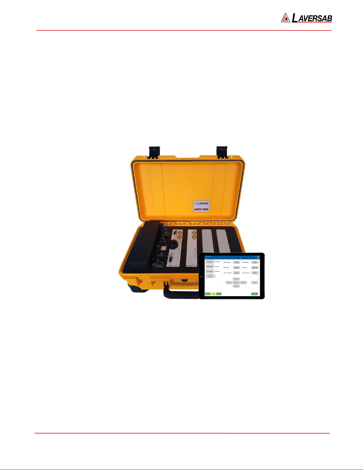
2.1.1. Test Set General
ARTS 7000 Test Set General View
ARTS 7000 Test Set in Use
The ARTS 7000 is housed in a high-quality ruggedized roller case.
Test Set Dimensions:
Approximate dimensions –ARTS 7000 main test set case measures 22” x 14” x 9” and
weighs 30 lbs or 56cm x 36cm x 23cm and weighs 14 kg. Weight dependent on
configuration.
ARTS 7000 lid latch in unused position
ARTS 7000 lid latch in operational position

ARTS 7000 User Manual Aviation Systems
Rev A3 Page 14
2.1.2. ARTS 7000 Test Set Top Panel
Item
Description
1
Battery –Removable battery
2
Power Switches and Connections –Power control
3
Nav/Com Module –Used for all Navigation and Communication functions.
4
Pulse Module –Used for all Pulse (Transponder/DME/TCAS) functions
5
Expansion Slot –Qty 2 Expansion Slots for future capability development
6
Ground Connector
7
Lid Latch –holds the test set lid in the open position during operation
1
2
3
4
5
6
7
5

ARTS 7000 User Manual Aviation Systems
Rev A3 Page 15
2.1.3. Power Switches and Connections
Item
Description
1
28V Fuse
2
DC Power connector for battery or external
28VDC power
3
Battery Fuse
4
DC Power Selector used to select DC power
source. Selections: 28VDC (External) - Off -
Battery
5
Unit Power Switch –Main Power switch for
setting the unit On - Off
6
Power LED Indicator Panel
•Unit: Lit when the ARTS 7000 is on and active.
•Power: Lit when the ARTS 7000 is has a suitable
power source available
•Charge LEDs: Indicate the charge state of the battery
7
AC Power Switch ON - Off
8
AC Power Fuse
9
AC Power connector –Aircraft AC or mains
outlet power connector - Suitable for any 90-
260VAC 47-400Hz 120VA AC source
1
2
3
4
5
6
7
8
9

ARTS 7000 User Manual Aviation Systems
Rev A3 Page 16
2.1.4. Nav/Com Module
Item
Description
1
USB Connector: Used for updating the software
within the ARTS 7000 Test Set.
2
Antenna connection (1W Maximum):
Used for connecting the ARTS 7000 Test Antenna
for over the air testing.
3
Cable Connection (100W Maximum):
Used for Direct /Cable connection between the
ARTS 7000 Test Set and a radio or antenna feeder.
4
WIFI Antenna
5
GPS Antenna
6
COM LED Indicator: Lit during an active COM
test.
7
LOC LED Indicator: Lit during an active LOC test.
8
GS LED Indicator: Lit during an active GS test.
9
OM LED Indicator: Lit when an Outer Mkr is
active.
10
MM LED Indicator: Lit when a Middle Mkr is
active.
11
IM LED Indicator: Lit when an Inner Mkr is active.
12
VOR LED Indicator: Lit during an active VOR test.
13
ADTS Connector: Used for a direct connection to a
Laversab Air Data Testing. This connection allows
both the ARTS 7000 and an ADTS to be controlled
by a single Tablet controller for
Altitude/Transponder encoder testing.
1
2
3
4
5
6
7
8
9
9
10
11
13
12

ARTS 7000 User Manual Aviation Systems
Rev A3 Page 17
2.1.5. Pulse Module
Item
Description
1
Antenna connection (1W Maximum):
Used for connecting the Test Antenna for
over-the-air testing.
2
Cable Connection (100W Maximum):
Used for Direct /Cable connecting the test
set directly to a radio or to antenna feeder.
3
DME LED Indicator: Lit during an active
DME test.
4
XPNDR LED Indicator: Lit during an active
Transponder test.
5
TCAS LED Indicator: Lit during an active
TCAS test. (TCAS functionality is optional)
6
TIS LED Indicator: Lit during an active TIS
test.
7
INTR LED Indicator: Lit whenever the
ARTS 7000 is sending an interrogation to
the Radio/Aircraft under test. (Normally
flashing during the Interrogation)
8
RPLY LED Indicator: Lit whenever the
ARTS 7000 is Receiving a reply from the
Radio/Aircraft under test. (Normally flashing
during the Reply)
1
2
3
4
5
6
7
8
ARTS 7000 User Manual Aviation Systems
Rev A3 Page 18
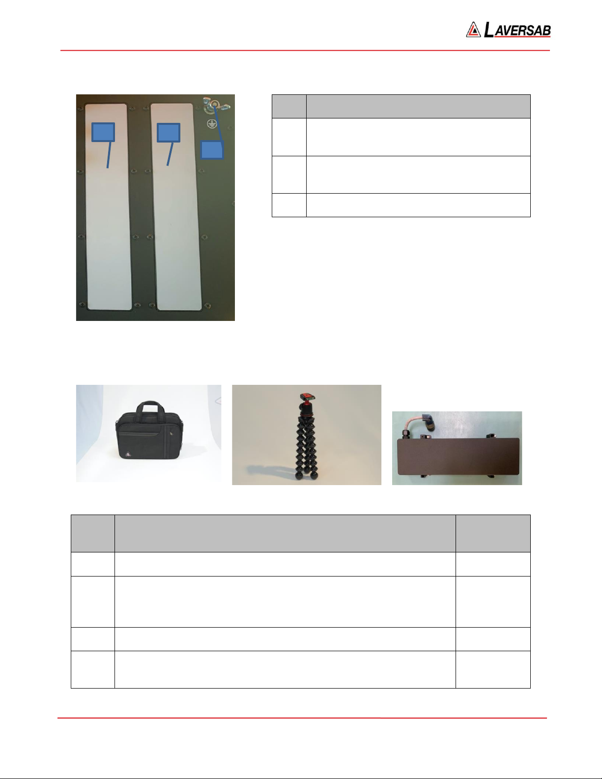
2.1.6. Expansion Slots
Item
Description
1
Expansion Slot Number 1: Used for future
capability expansion.
2
Expansion Slot Number 2: Used for future
capability expansion.
3
Ground Connection point.
2.1.7. General accessories
1. Accessory Storage case
2. Antenna Mounting Tripod
3. Battery
Item
Description
Part
Number
1
Accessory Storage case used to hold and transport antenna cables etc.
118-1945
2
Antenna Mounting Tripod. Used to mount the Pulse antenna but can
also be used to mount the Nav/Com antenna remotely from the ARTS
7000 Test Set using the supplied Mounting adapter.
118-2286
3
Removable Battery
115-1282
Not
Shown
External Battery Charger
115-1304
1
2
3

ARTS 7000 User Manual Aviation Systems
Rev A3 Page 19
2.1.8. Nav Com Antenna
Item
Description
Part Number
1 & 2
Telescopic Antenna for all Nav Com Functions.
123-0239
3
NAV/Com Telescopic Antenna tripod mounting adapter.
This adapter is used to allow the Nav Com antenna to be
mounted onto the tripod for remote operation from the ARTS
7000.
116-0349
1. NAV/COM Telescopic antenna in
operation on an ARTS 7000 Test Set
2. Telescopic
antenna
3. NAV/Com Telescopic Antenna
tripod mouting adater

ARTS 7000 User Manual Aviation Systems
Rev A3 Page 20
2.1.9. Pulse Antenna
1. Pulse Antenna mounted on tripod.
2. Pulse antenna in use.
Item
Description
Part Number
1
Pulse antenna: The Pulse Antenna is used for all test functions relating
to the pulse module –Transponder, DME and TCAS testing. The
antenna is mounted on a tripod to allow convenient positioning of the
antenna with respect to the aircraft antenna. The Pulse antenna is
designed to be highly directional and as such, careful alignment
between the ARTS 7000 Pulse antenna and the aircraft system under
test antenna is required.
NOTE the front of the antenna that should be directed to the antenna
under test is the side embossed with the Laversab name and Logo.
123-0230
WARNING
The Pulse Antenna is highly directional and sensitive. Please make sure that visual alignment checks are made before operating this antenna
during test function.
Other manuals for ARTS 7000
1
Table of contents
Other Laversab Test Equipment manuals


Popular Test Equipment manuals by other brands


Klein Tools
Klein Tools RT250 user manual

MULTILANE
MULTILANE ML4035 user guide

SIGLENT TECHNOLOGIES
SIGLENT TECHNOLOGIES SDS6000A Series quick start

Testboy
Testboy Profi III LCD+ operating instructions

Teledyne Lecroy
Teledyne Lecroy WaveSurfer 3000z Operator's manual

yellow jacket
yellow jacket RecoverXLT2-AP Operation and maintenance manual