Laversab ARTS 7000 User manual
ARTS 7000 User Manual Aviation Systems
Rev A6 Page 1
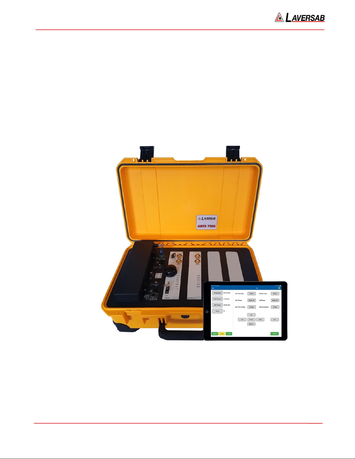
Avionics Radio Test Set 7000
(ARTS 7000)
Date: 10 November 2021

ARTS 7000 User Manual Aviation Systems
Rev A6 Page 2
WARRANTY
Laversab Inc., warrants its products to conform to or exceed the specifications as set forth in its
catalogues in use at the time of sale and reserves the right, at its own discretion, without notice and
without making similar changes in articles previously manufactured, to make changes in materials,
designs, finish, or specifications. Laversab Inc. warrants products of its own factory against defects
of material or workmanship for a period of three years from date of sale.
Liability of Laversab Inc. under this warranty shall be limited to replacing, free of charge (FOB
Houston, Texas), any such parts proving defective within the period of this warranty, but Laversab
Inc. will not be responsible for transportation charges, consequential or incidental damages. No
liability is assumed by Laversab for damages that are caused by misuse or abuse of the product.
The warranty of Laversab Inc. is not made for products manufactured by others which are illustrated
and described in Laversab catalogues or incorporated in Laversab products in essentially the same
form as supplied by the original manufacturer. Warranties of the original manufacturers supplant the
warranty of Laversab Inc., but, in applicable instances, the latter agrees to use its best efforts to have
original suppliers make good their warranties.
COPYRIGHT NOTICE
Copyright (c) 1982-2021 by Laversab Inc. All rights reserved. The content of this manual may not be
reproduced in any form by any means, in part or in whole, without the prior written permission of
Laversab Inc.
DISCLAIMER
No representations or warranties are made with respect to the contents of this user's manual.
Further, Laversab Inc. reserves the right to revise this manual and to make changes from time to
time in the content hereof without obligation to notify any person of such revision.
ARTS 7000 User Manual Aviation Systems
Rev A6 Page 3
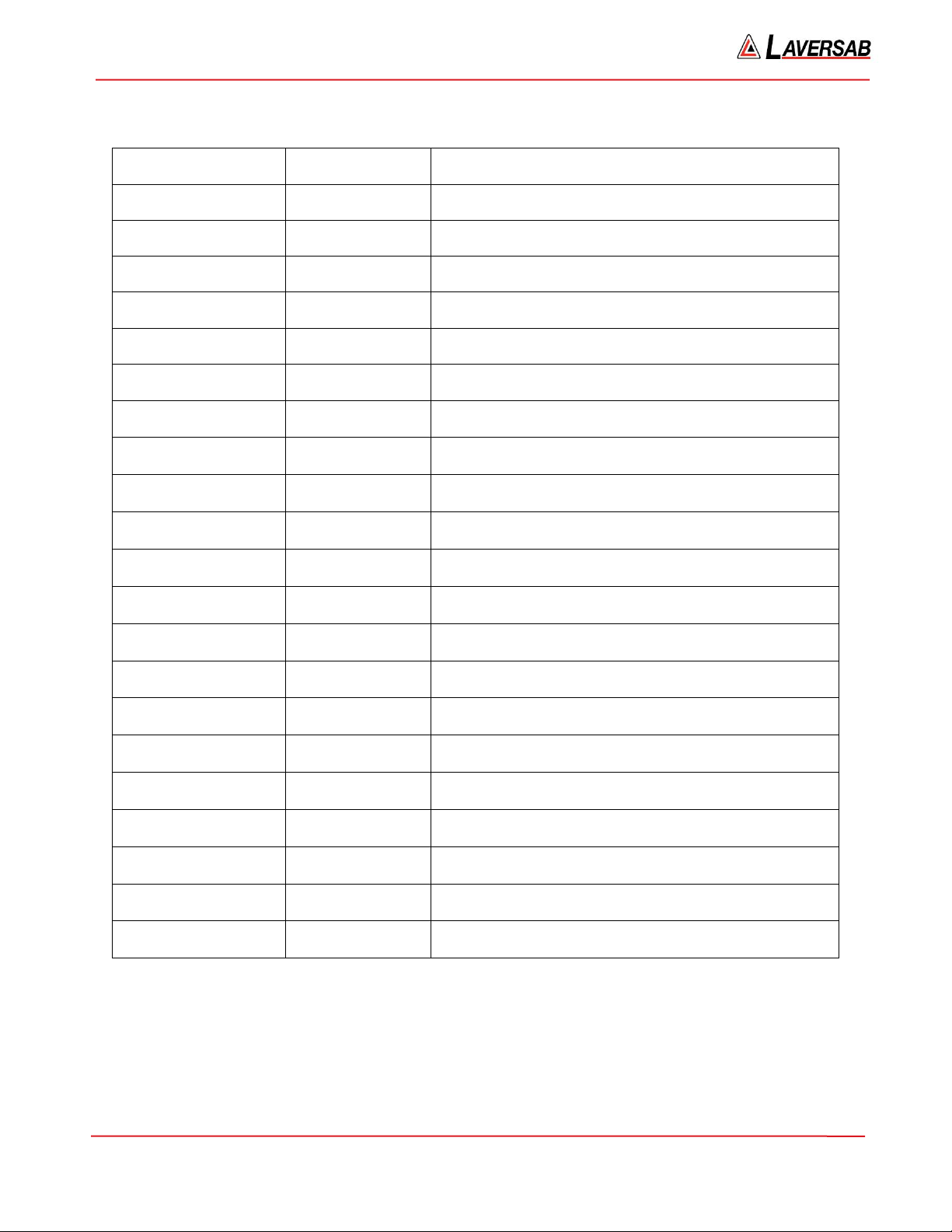
REVISION HISTORY
Document No.
Release Date
Description
125-9120A1
27 Jul 2020
ARTS-7000 User Manual Rev A1
125-9120A2
31 Aug 2020
ARTS-7000 User Manual Rev A2
125-9120A3
19 Nov 2020
ARTS-7000 User Manual Rev A3
125-9120A4
05 Feb 2021
ARTS-7000 User Manual Rev A4
125-9120A4IAF
11 Apr 2021
ARTS-7000 User Manual Rev A5 IAF version
125-9120A6
10 Nov 2021
ARTS-7000 User Manual Rev A6

ARTS 7000 User Manual Aviation Systems
Rev A6 Page 4
WARNING
THE ARTS 7000 USES LINE VOLTAGES AND RADIO FREQUENCY SIGNALS FOR ITS OPERATION
WHICH ARE POTENTIALLY DANGEROUS.
IMPROPER OPERATION OF THIS EQUIPMENT MAY RESULT IN PERSONAL INJURY OR LOSS OF
LIFE. HENCE THE EQUIPMENT DESCRIBED IN THIS MANUAL SHOULD BE OPERATED ONLY BY
PERSONNEL TRAINED IN PROCEDURES THAT WILL ASSURE SAFETY TO THEMSELVES, TO
OTHERS AND TO THE EQUIPMENT.
BEFORE PERFORMING ANY MAINTENANCE, TURN THE POWER OFF AND DISCONNECT THE
POWER CORD FROM THE POWER SOURCE.
ALWAYS USE A 3-PIN GROUNDED OUTLET AS YOUR AC POWER SOURCE.

ARTS 7000 User Manual Aviation Systems
Rev A6 Page 5
TABLE OF CONTENTS
Warranty ....................................................................................................................................................................... 2
Copyright Notice ........................................................................................................................................................... 2
Disclaimer ...................................................................................................................................................................... 2
Revision History ............................................................................................................................................................ 3
WARNING .................................................................................................................................................................... 4
Notes on this document ................................................................................................................................................. 8
Section 1: INTRODUCTION ....................................................................................................................................... 9
Subsection 1: Description .................................................................................................................................... 9
Subsection 2: ARTS 7000 Outline Overview ........................................................................................................ 9
Subsection 3: Key Capabilities ........................................................................................................................... 10
Subsection 4: Key Features ................................................................................................................................ 11
Section 2: Controller & User Interface ..................................................................................................................... 12
Subsection 1: Description of Test Controller Application .................................................................................. 12
Subsection 2: Menu Structure & Functions ....................................................................................................... 12
Section 3: ARTS 7000 Test Control Application ..................................................................................................... 20
Subsection 1: Test Control Application – Normal or Demo/Training Mode ...................................................... 20
Subsection 2: Power up, Wi-Fi connection and Application Start ..................................................................... 20
Subsection 3: Generic Controls and Indicators .................................................................................................. 23
Section 4: ARTS 7000 Test Control Application Menus ......................................................................................... 25
Subsection 1: The Utilities Menu ....................................................................................................................... 26
Subsection 2: Documentation Menu ................................................................................................................. 31
Section 5: ARTS 7000 Software Updates .................................................................................................................. 33
Subsection 1: Test Controller Application Software Update ............................................................................. 33
Subsection 2: ARTS 7000 Firmware Update ...................................................................................................... 33
Section 6: ARTS 7000 Test Set Hardware Controls & Connections ...................................................................... 39
Subsection 1: ARTS 7000 Test Set Hardware, Controls & Connections ............................................................. 39
Subsection 2: Hardware & Antenna Test Configuration ................................................................................... 48
Subsection 3: Direct Connections and Antenna Set Up .................................................................................... 49
Section 7: Antenna Coupler ....................................................................................................................................... 52
Subsection 1: Antenna Coupler Description ...................................................................................................... 52
Subsection 2: Antenna Coupler Setup and Operation ....................................................................................... 54
Section 8: Integrated Landing System (ILS) Operation ......................................................................................... 55
Subsection 1: ILS Operation ............................................................................................................................... 55
Other manuals for ARTS 7000
1
Table of contents
Other Laversab Test Equipment manuals


Popular Test Equipment manuals by other brands


Redtech
Redtech TRAILERteck T05 user manual

Venmar
Venmar AVS Constructo 1.0 HRV user guide

Test Instrument Solutions
Test Instrument Solutions SafetyPAT operating manual

Hanna Instruments
Hanna Instruments HI 38078 instruction manual

Kistler
Kistler 5495C Series instruction manual

Waygate Technologies
Waygate Technologies DM5E Basic quick start guide

StoneL
StoneL DeviceNet CK464002A manual

Seica
Seica RAPID 220 Site preparation guide

Kingfisher
Kingfisher KI7400 Series Training manual

Kurth Electronic
Kurth Electronic CCTS-03 operating manual

SMART
SMART KANAAD SBT XTREME 3G Series user manual

Agilent Technologies
Agilent Technologies BERT Serial Getting started