Laversab 6150 User manual

MODEL 6150
USER'S MANUAL
LAVERSAB INC.,
505 GILLINGHAM LN.
SUGAR LAND, TEXAS 77478.
PHONE: (281) 325-8300
FAX: (281) 325-8399
Email: customerservice@laversab.com
Document Number: 9052
Date: Mar.11, 2011.

i
WARRANTY
Laversab Inc., warrants its products to conform to or exceed the specifications as set
forth in its catalogs in use at the time of sale and reserves the right, at its own discretion,
without notice and without making similar changes in articles previously manufactured,
to make changes in materials, designs, finish, or specifications. Laversab Inc. warrants
products of its own factory against defects of material or workmanship for a period of one
year from date of sale.
Liability of Laversab Inc. under this warranty shall be limited to replacing, free of
charge (FOB Houston, Texas), any such parts proving defective within the period of this
warranty, but Laversab Inc. will not be responsible for transportation charges,
consequential or incidental damages. No liability is assumed by Laversab for damages
that are caused by misuse or abuse of the product.
The warranty of Laversab Inc. is not made for products manufactured by others
which are illustrated and described in Laversab catalogs or incorporated in Laversab
products in essentially the same form as supplied by the original manufacturer.
Warranties of the original manufacturers supplant the warranty of Laversab Inc., but, in
applicable instances, the latter agrees to use its best efforts to have original suppliers make
good their warranties.

ii
COPYRIGHT NOTICE
Copyright (c) 2008 onward by Laversab Inc. All rights reserved. The content of this
manual may not be reproduced in any form by any means, in part or in whole, without
the prior written permission of Laversab Inc.
DISCLAIMER
No representations or warranties are made with respect to the contents of this user's
manual. Further, Laversab Inc. reserves the right to revise this manual and to make
changes from time to time in the content hereof without obligation to notify any person of
such revision.

iii
REVISION HISTORY
Document No. Release Date Description
9052
10/10/2008
Model 6150 User’s Manual
9052
03/11/2011
Model 6150 Rev B1 User’s Manual

iv
WARNING
THE 6150 USES LINE VOLTAGES FOR ITS OPERATION WHICH ARE POTENTIALLY
DANGEROUS. IMPROPER OPERATION OF THIS EQUIPMENT MAY RESULT IN
PERSONAL INJURY OR LOSS OF LIFE. HENCE THE EQUIPMENT DESCRIBED IN
THIS MANUAL SHOULD BE OPERATED ONLY BY PERSONNEL TRAINED IN
PROCEDURES THAT WILL ASSURE SAFETY TO THEMSELVES, TO OTHERS AND TO
THE EQUIPMENT.
BEFORE PERFORMING ANY MAINTENANCE, TURN THE POWER OFF AND
DISCONNECT THE POWER CORD FROM THE POWER SOURCE.
ALWAYS USE A 3-PIN GROUNDED OUTLET AS YOUR AC POWER SOURCE

v
TABLE OF CONTENTS
Warranty ............................................................................................................................. i
Copyright notice, disclaimer ............................................................................................... ii
Revision History ................................................................................................................... iii
Warning ............................................................................................................................. iv
Section 1: Introduction .................................................................................................. 1
Section 2: Functional Details ........................................................................................ 5
2.1 Power On .................................................................................................................. 5
2.2 Limits and Leak-times ............................................................................................. 5
2.3 Main Screen .............................................................................................................. 7
2.4 Leak Check Mode ..................................................................................................... 12
2.5 Functions ................................................................................................................... 14
Section 3: Typical Use .................................................................................................... 18
3.1 Setup .......................................................................................................................... 18
3.2 Low-level leak checks ............................................................................................. 18
3.3 High-Altitude leak check ..................................................................................... 19
3.4 Airspeed accuracy check ........................................................................................ 19
3.5 Altimeter accuracy check ....................................................................................... 20
Section 4: Calibration .................................................................................................... 22
4.1 Equipment ................................................................................................................ 22
4.2 Calibration Procedure ............................................................................................. 22
4.3 Calibration Report ................................................................................................. 26
Section 5: Maintenance ..................................................................................................... 28
Appendix A: Specifications ................................................................................................ 29
Appendix B: Repair and Return Policies ......................................................................... 30

1
SECTION 1
INTRODUCTION
The 6150 Digital Air Data and Leak Tester is a high accuracy Pitot Static Tester which can
be used for performing leak checks on the Pitot and Static systems of all aircraft. It can
also be used to perform accuracy checks on altimeters, airspeed indicators, air data
computers and other air data related equipment on-board aircraft. However, such
accuracy checks must be limited only to aircraft that are not RVSM compliant. The 6150 is
NOT RVSM compliant. However, the relatively high accuracy (see specifications) of the
6150 makes it suitable for use to perform only leak-checks even on RVSM compliant
aircraft.
The 6150 has powerful built-in pumps for vacuum and pressure. Altitudes and Airspeeds
can be simulated on the Static and Pitot outputs by using the metering valves provide on
the unit. There is no maintenance required on the 6150, other than the annual calibration.
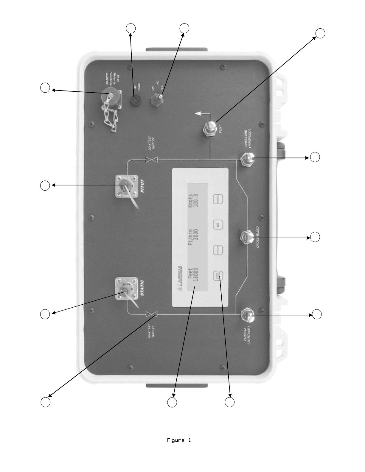
The top panel of the 6150 is shown in Figure 1. The different components on the top
panel, indicated by numbers in Figure 1, are explained below.
1. Static output port
This #4-AN port is normally connected to the Static port of the aircraft. As an option, this
port can also be fitted with a #6-AN fitting.
2. Pitot output port
This #4-AN port is normally connected to the Pitot port of the aircraft.
3. AC input connector
This 3-pin circular connector accepts AC input power for the unit. AC power between 90-
260 VAC and 47-440 Hz is suitable for the unit. Nominal power consumption is 70 VA.
4. AC Fuse
The AC input power is fused with a 1 amp slow-blow, 20 mm fuse.
5. ON /OFF switch
This is used to turn power to the unit, ON or OFF.
2
2
1 2 3
4
5
6
7
8
9
12
11
10

3
6. VENT metering valve
This valve is used to vent-to-ambient, pressure or vacuum from the Pitot output. With the
Cross-bleed valve open, the Vent valve can also vent-to-ambient, pressure or vacuum
from the Static system.
CAUTION : This metering valve seals before it reaches its STOP. Do Not tighten at all
past this STOP. Not even finger-tight. Any tightening past the STOP may cause
permanent damage to the valve and it will constantly leak.
7. PRESSURE or AIRSPEED metering valve
This valve is used for increasing airspeed or pressure at the Pitot output. With the Cross-
bleed valve open, it can also be used to create pressure on the Static port for altitudes
below field elevation (like -1000 feet) .
CAUTION : This metering valve seals before it reaches its STOP. Do Not tighten at all
past this STOP. Not even finger-tight. Any tightening past the STOP may cause
permanent damage to the valve and it will constantly leak.
8. CROSS-BLEED valve
When this valve is open it equalizes pressure between the Pitot and Static outputs and
provides Zero airspeed.. When this valve is closed it isolates the Pitot and Static outputs
and allows the user to create a specific airspeed, either by opening the Vent valve or the
Pressure valve.
CAUTION : This metering valve seals before it reaches its STOP. Do Not tighten at all
past this STOP. Not even finger-tight. Any tightening past the STOP may cause
permanent damage to the valve and it will constantly leak.
9. VACUUM or ALTITUDE valve
Opening this valve increases altitude or vacuum on the Static output. If the Cross-bleed
valve is closed while altitude (vacuum) is increased on the Static output, this will cause
airspeed to increase automatically on the Pitot output, even if the Vent valve is open, since
the difference between Pitot pressure and Static pressure increases. If the Cross-bleed
valve is open and the Vent valve and Pressure valve are closed, opening the Vacuum
valve will increase altitude on the Static output but maintain close to Zero airspeed on the
Pitot output.
CAUTION : This metering valve seals before it reaches its STOP. Do Not tighten at all
past this STOP. Not even finger-tight. Any tightening past the STOP may cause
permanent damage to the valve and it will constantly leak.

4
10. Keypad
There are four keys:
The LEAK CHECK key is used to enter the Leak-test mode, and also for some other
functions.
The FUNCTIONS key is used to scroll through several functions (detailed later). It is also
used for some other actions.
The GO key is used to execute certain commands or options.
The CANCEL key is used to cancel certain commands or functions. This key is also used
to return to the Main Screen on the display.
11. Display
All indicators and readings are shown on this 40-character by 4-line LCD display. The
display is backlit for easy viewing in all lighting conditions. The various screens shown on
the display are explained in detailed in Section 2.
12. LEAK-TEST SHUTOFF solenoid-valves
There are two valves, one on the Static output and one on the Pitot output. During the
Leak-test mode, both of these solenoid-valves are automatically closed to isolate the
aircraft from the metering valves of the 6150. The 6150 can still monitor the altitude and
airspeed on the Static and Pitot ports. However, once the solenoid-valves are closed, none
of the metering valves will have any effect on the pressure (or vacuum) on the Static or
Pitot outputs.

5
SECTION 2
FUNCTIONAL DETAILS
This section explains all the different screens and functions of the 6150.
2.1 Power On.
When power is turned ON to the 6150, the display shows the sign-on screen for 3 seconds.
The pumps remain OFF. After the sign-on screen, the display shows the Limits and
Leak-times screen.
2.2 Limits and Leak-times
The Limits and Leak-times screen shows the current setting of the user-programmable
value for the maximum altitude limit and maximum airspeed limit. It also shows the
current setting for the three programmable leak time periods. This screen is displayed
only after power-up.
The minimum altitude limit is always set at -1200 feet and cannot be changed. The
minimum airspeed limit is set to -20 knots and cannot be changed.
The leak time periods are used in the leak test mode where the 6150 displays the altitude
and airspeed at the end of the specified time period and also the accumulated leak in
altitude and airspeed over that time period. For example, if the leak timers are set for 3, 5
and 10 minutes and the leak check was started at 10000 feet, then at the end of 3 minutes if
the altitude was at 9500 feet then the accumulated leak over 3 minutes is 500 feet. So the
6150 would display the values 9500 and 500. The airspeed leak at the end of 3 minutes
would be shown in the same manner. The process is repeated at the end of 5 minutes and
10 minutes also.
Please refer to the details on “Leak Check Screen”, later in this section.
The Limits and Leak-times screen appears as below.
Max Alt.= 31000 ft. Max Airsp.= 310 kts
Leak timers: 3, 5, 10 minutes
FUNCTIONS: Change GO: Accept

6
The screen shows that the maximum altitude limit is set to 31000 feet and the maximum
airspeed limit is set to 310 knots. The leak timers are set for 3, 5 and 10 minute intervals.
To make changes to values, press the FUNCTIONS key. To accept the values as they
appear, press GO. If the FUNCTIONS key is pressed to make a change, the next screen
that appears is shown below.
Max Altitude = 31000 ft.
LEAK CHECK: Incr.
FUNCTIONS: Decr. GO: Accept
This screen allows the max altitude limit to be changed. Pressing LEAK CHECK increases
the limit by 1000 feet.. Pressing FUNCTIONS decreases the value by 1000 feet. The
maximum altitude limit can be changed in steps of 1000 feet, between a minimum value of
10,000 ft. and a maximum of 60,000 ft. It is recommended that the limit be set to a value
that is at least 1000 feet higher than the maximum altitude that will normally be generated
with the 6150 for the user’s typical aircraft. For example, if the user will normally perform
tests up to 30,000 ft. then the limit should be set at 31,000 ft..
Once the value of the limit is acceptable, pressing GO will accept the selected value and
move to next screen shown below.
Max Airspeed = 310 knots
LEAK CHECK: Incr.
FUNCTIONS: Decr. GO: Accept
This screen allows the max airspeed limit to be changed, using the LEAK CHECK and
FUNCTIONS keys, in increments of 10 knots. The limit can be changed between 100 knots
and 500 knots. The limit should be set at least 10 knots above “normal-usage” airspeed, i.e.
if the tester will normally be used up to 300 knots then the limit should be set to 310 knots.
Press GO to accept the value for max. airspeed. This will bring up the next screen shown
below
Leak-time 1= 3 min. Leak-time 2= 5 min.
Leak-time 3= 10 min.
LEAK CHECK: Incr.
FUNCTIONS: Decr. GO: Accept
This screen allows the user to select the value for leak-time 1. The value will increment or
7
decrement in steps of 1 minute. The minimum value for leak-time 1 is 1 minute and the
maximum is 18 minutes. When GO is pressed, the displayed value is accepted and the
screen changes as shown below:
Leak-time 1= 3 min. Leak-time 2= 5 min.
Leak-time 3= 10 min.
LEAK CHECK: Incr.
FUNCTIONS: Decr. GO: Accept
This screen allows the user to select the value for leak-time 2. The value will increment or
decrement in steps of 1 minute. The minimum value for leak-time 2 is one minute higher
than leak-time 1 and the maximum is 19 minutes. When GO is pressed, the displayed
value is accepted and the screen changes as shown below:
Leak-time 1= 3 min. Leak-time 2= 5 min.
Leak-time 3= 10 min.
LEAK CHECK: Incr.
FUNCTIONS: Decr. GO: Accept
This screen allows the user to select the value for leak-time 3. The value will increment or
decrement in steps of 1 minute. The minimum value for leak-time 3 is one minute higher
than leak-time 2 and the maximum is 20 minutes. When GO is pressed, the displayed
value is accepted and the screen changes as shown below:
Max Alt.= 31000 ft. Max Airsp.= 310 kts
Leak timers: 3, 5, 10 minutes
FUNCTIONS: Change GO: Accept
Press GO to accept the changes. You will now exit the Limits and Leak-times screen and
the next screen will appear as shown below.
2.3 Main Screen
Most of the operations to control and achieve specific altitudes and airspeeds will be done
while in this screen, shown below:
Feet Ft/min. knots
425 0 6.5
Press GO to start pumps

8
In this screen, (the values displayed on your screen will likely be different), 425 feet is the
altitude being measured at the Static output of the 6150 and 6.5 knots is the airspeed being
measured at the Pitot output. There is no change of altitude so the VSI is indicated as 0
ft/min.
Please note that any VSI values below 20 ft/min will be shown as 0 ft/min.
Pumps are normally off and can be started by pressing GO.
Under certain conditions the pumps will be turned OFF automatically (see section 2.3.7)
Before starting the pumps, please ensure that all 4 metering valves are closed.
Before starting the pumps, please connect the Pitot and Static outputs to the aircraft.
While in the Main Screen, the metering valves can be used to change the altitude at an
appropriate VSI (Ft/min), and also the airspeed. The recommended method for using
these metering valves is shown below. This method is the simplest way to achieve desired
altitudes and airspeeds, without having to operate more than one metering valve at a
time.
2.3.1 Changing airspeed while maintaining altitude at ambient (Ground).
Increase airspeed: Close all valves. Slowly open the Pressure (Airspeed) valve while
watching the knots value increase. When the desired knots value is achieved, close the
Pressure (Airspeed) valve.
Decrease airspeed: Close all valves. Slowly open the Vent valve until the desired airspeed
is achieved, then close the Vent valve.. An airspeed between -15 knots and +15 knots is
essentially equal to zero airspeed.
2.3.2 Changing Altitude while maintaining zero airspeed.
Keeping airspeed near zero while changing altitude is the ideal way to move from one
altitude to another. Please note that keeping airspeed near zero will NOT damage the
airspeed indicator on the aircraft.
Close all valves. Slowly open the Cross-bleed valve until airspeed is close to zero. Then
open the Cross-bleed valve all the way and leave it open. This ensures that airspeed will
always stay close to zero while altitude is increased or decreased.
Increase altitude: Slowly open the Vacuum valve while watching the VSI (Ft/min).
The displayed VSI value is heavily damped. Please allow a few seconds for the VSI
value to stabilize after making any changes to the Vacuum valve.
Once a desired VSI is achieved, it will reduce very slowly, and it may not be necessary to

9
constantly make changes to the Vacuum valve. Slowly close the Vacuum valve as you
approach the desired altitude.
Decrease altitude: Close the Vacuum valve completely, then slowly open the Vent valve
while watching the VSI. This will allow you to achieve altitudes all the way down to
Ground. If an altitude below Ground is desired (like -1000 ft.) then close the Vent valve
and slowly open the Pressure valve while watching the VSI. To return to Ground altitude,
close the Pressure valve and slowly open the Vent valve.
Note that during all these operations, the Cross-bleed valve is completely open and
therefore, airspeed will be close to zero.
2.3.3 Changing Airspeed while maintaining an Altitude other than Ground
Increase airspeed: Close the Cross-bleed valve. Slowly open the Pressure valve (or the
Vent valve) until the desired airspeed is achieved. The Vent valve will work only for
airspeeds below ambient pressure.
Decrease airspeed: Close the Pressure valve (and Vent valve). Then slowly open the
Cross-bleed valve until the desired airspeed is achieved. Notice that as the Cross-bleed
valve is opened, the Altitude will also decrease. Watch the VSI as the Cross-bleed valve is
opened.
2.3.4 Maintaining a positive Airspeed while changing Altitude.
This requires making constant changes to two valves simultaneously and is therefore
NOT a recommended method. However if it is absolutely necessary to follow this
method, please follow the steps below.
Increase altitude: First achieve the desired positive airspeed using the Pressure valve
while keeping the other valves closed. Close the Pressure valve. Open the Vacuum valve
slowly. As the altitude increases, the airspeed will also increase. Reduce the airspeed to
the desired value by opening the Cross-bleed valve. You will need to constantly adjust the
Vacuum and Cross-bleed valves to maintain the desired VSI and the desired positive
airspeed. When the desired altitude is achieved, close both the Vacuum and Cross-bleed
valves. The Cross-bleed valve should be closed before the Vacuum valve to maintain the
desired positive airspeed.
Decrease altitude: First achieve the desired positive airspeed using the Pressure valve
while keeping the other valves closed. Close the Pressure valve. Slowly open the Cross-
bleed valve. This will cause the airspeed to decrease and the altitude also to decrease.
Increase the airspeed to the desired value by opening the Pressure valve. You will need to
constantly adjust the Pressure and Cross-bleed valves to maintain the desired VSI and the
desired positive airspeed. When the desired altitude is achieved, close both the Pressure
and Cross-bleed valves. The Cross-bleed valve should be closed before the Pressure valve
to maintain the desired positive airspeed.

10
2.3.5 Checking for leaks in the Main Screen
When an altitude and airspeed have been achieved, it is possible to check for leaks
without going into the Leak Test screen.
If the Cross-bleed valve is open and the other three valves are closed, the altitude value
shown on the display will indicate the leak of both the Static and Pitot system combined.
Do NOT pinch-off either hose to the aircraft to try and isolate the leak between Pitot
and Static sides. This could cause a large negative airspeed on the aircraft.
To isolate the Pitot and Static systems, close the Cross-bleed valve and open the Pressure
(or Vent) valve to increase the airspeed to about 100 knots. Then, with all valves closed,
the true Static leak will be shown on the displayed altitude value. However, it will still not
be possible to determine the true Pitot leak since the displayed airspeed value will change
depending on both the Static and Pitot leaks.
To determine the true Pitot leak while at an altitude other than Ground, keep all valves
closed and a positive airspeed of approximately 100 knots. Then open the Vacuum valve
slowly to hold the altitude steady at a fixed value. By doing this you are compensating for
the Static leak. Now the displayed airspeed value will indicate the true Pitot leak.
Please note that if altitude is more than 500 feet above Ground and airspeed is around
100 knots, a Pitot leak will cause airspeed to INCREASE.
The ideal way to perform a Pitot leak check is while holding Static at Ground, as follows.
Close all valves. Ensure that both Pitot and Static are at Ground by opening the Cross-
bleed valve and then the Vent valve. Once Ground is achieved, close Cross-bleed and
Vent valves. Slowly open the Pressure valve to achieve 100 knots. Close the Pressure
valve. The true Pitot leak can be observed on the displayed airspeed value. In this
situation, any leak Pitot leak will always cause airspeed to decrease.
2.3.6 Protection against Negative Airspeed
The 6150 has built-in protection against excessive negative airspeed. An internal relief-
valve prevents the airspeed from going more negative than about -30 knots.
This relief-valve is active even when the 6150 is powered-off.
There are two conditions during the operation of the 6150 when the internal relief-valve
will NOT protect against negative airspeed.
a. During Leak-Check Mode, the Leak Test Shutoff solenoids are closed. This prevents
the relief-valve from providing the negative airspeed protection to the aircraft. Therefore,
in Leak-Check Mode, if the 6150 detects negative airspeed, it automatically trips out of
Leak-Test Mode and opens the Leak Test Shutoff solenoids, thereby allowing the
relief-valve to provide protection against excessive negative airspeed.

11
b. During Calibration Mode, the Leak Test Shutoff solenoids are closed. This prevents the
relief-valve from providing the negative airspeed protection. However, this protection is
normally not required during Calibration Mode.
2.3.7 Warnings
While in the Main Screen, several warning messages are displayed to alert the user to
existing or potential error conditions. These messages are automatically cleared when the
error condition no longer exists. Warning messages are displayed for the following
conditions.
a. Airspeed close to limit : Indicates that at the rate at which airspeed is being changed, it
will exceed the limit within 10 seconds. Usually, slowing down the rate of change of
airspeed will clear the message.
b. Airspeed is negative : Indicates that airspeed is more negative than -20 knots. Opening
the Cross-bleed valve or the Pressure valve will usually make airspeed more positive.
c. Airspeed over limit : Indicates that airspeed is over the programmed limit.
Under this condition, the pumps will automatically be turned OFF.
If altitude is at Ground, reduce airspeed by opening the Vent valve. If altitude is above
Ground, reduce airspeed by opening the Cross-bleed valve. After the airspeed is below
the limit, close all valves and then turn ON the pumps
d. Altitude close to limit : Indicates that at the rate at which altitude is being changed, it
will exceed the limit within 10 seconds. Usually, reducing the VSI will clear the message.
e. Altitude over limit : Indicates that altitude is either over the programmed max. limit or
below -1200 feet.
Under this condition, the pumps will automatically be turned OFF.
To decrease altitude from a high value, open the Cross-bleed valve and then the Vent
valve. To increase altitude from a negative value, open the Vent valve. If the airspeed
starts going negative, open the Cross-bleed valve also. After the altitude is within limits,
close all valves and then turn ON the pumps.
f. Any combination of the above 5 conditions will generate other warning messages.
A list of all the warning messages is shown below:
** Airspeed close to limit **
** Airspeed over limit **
** Airspeed is negative **

12
** Altitude close to limit **
** Altitude over limit **
** Alt and A/S close to limits **
** Alt and A/S over limits **
** A/S negative, Alt over limit **
** A/S negative, Alt close to limit **
** A/S over limit, Alt close to limit **
** Alt over limit, A/S close to limit **
2.4 Leak Check Mode
The Leak Check mode is used to perform an accurate timed leak-check of the Pitot and
Static systems of the aircraft. During the Leak Check mode, both Pitot and Static systems
are leak-checked simultaneously. Before entering the Leak Check mode, you must achieve
the desired altitude and airspeed at which the leak check is to be performed. This is done
using the metering valves while in the Main Screen (section 3 above).
Once the desired altitude and airspeed have been achieved, enter the Leak Check mode by
pressing the LEAK CHECK key. The Leak Test Shutoff solenoids will close. This will
isolate the Pitot and Static outputs from the pumps and the metering valves.
In Leak Check mode the aircraft is not protected against negative airspeed. If a negative
airspeed condition exists, the 6150 will automatically trip out of Leak Check mode to
prevent excessive negative airspeed. See section 2.3.6 above.
Within 10 seconds of entering the Leak Check mode, the pumps will automatically turn
OFF. At that point, all four metering valves should be closed.
You may exit out of Leak Check mode, back to the Main Screen, at any time by pressing
the CANCEL key.
In Leak Check mode the display appears as below (actual values may be different)
5000 feet 0 ft/min. 100.0 kts
1m: / /
2m: / /
3m: / 00:02 /
The top line shows the actual measured values at the Static and Pitot outputs. These are
updated every 0.25 seconds. Please note that any VSI values below 20 ft/min will be
shown as 0 ft/min.
The center of the 4th line shows the elapsed time in minutes and seconds (mm:ss).

13
The start of the second, third and fourth lines show “1m:”, “2m:” and “3m:” which
indicates that the leak times have been programmed for 1, 2 and 3 minutes. For changing
leak-time values please see Section 2.2.
At the end of 1 minute of elapsed time, the display appears as below:
4995 feet 0 ft/min. 99.8 kts
1m: 4995 / 5 99.8 / 0.2
2m: / /
3m: / 01:00 /
Line 2 now shows that at the end of 1 minute, the altitude was 4995 ft. and the amount of
altitude leak over 1 minute was 5 feet. Also, the airspeed was 99.8 knots and the amount
of airspeed leak over 1 minute was 0.2 knots.
Although line 1 will continue to update, line 2 will remain as shown.
At the end of 2 minutes of elapsed time, the display appears as below:
4991 feet 0 ft/min. 99.6 kts
1m: 4995 / 5 99.8 / 0.2
2m: 4991 / 9 99.6 / 0.4
3m: / 02:00 /
Line 3 now shows that at the end of 2 minutes, the altitude was 4991 ft. and the total
amount of altitude leak over 2 minutes was 9 feet. Also, the airspeed was 99.6 knots and
the total amount of airspeed leak over 2 minutes was 0.4 knots.
Although line 1 will continue to update, lines 2 and 3 will remain as shown.
At the end of 3 minutes of elapsed time, the display appears as below:
4988 feet 0 ft/min. 99.5 kts
1m: 4995 / 5 99.8 / 0.2
2m: 4991 / 9 99.6 / 0.4
3m: 4988 / 12 03:00 99.5 / 0.5
Line 4 now shows that at the end of 3 minutes, the altitude was 4988 ft. and the total
amount of altitude leak over 3 minutes was 12 feet. Also, the airspeed was 99.5 knots and
the total amount of airspeed leak over 3 minutes was 0.5 knots.
Although line 1 and the timer will continue to update, lines 2, 3 and 4 will remain as

14
shown.
Once the timed leak has completed you should record all the displayed values before
returning to the Main Screen by pressing CANCEL. The values shown on the display for
the timed leaks are automatically recorded internally in the 6150 and may be retrieved
later. Please see section 5.1 for more details.
When CANCEL is pressed to exit out of the Leak Check mode, the Leak Test Shutoff
solenoids are opened and the Main Screen is displayed.
2.4.1 Warnings in Leak Check mode
While in the Leak Screen, several warning messages are displayed to alert the user to
existing or potential error conditions. These messages are automatically cleared when the
error condition no longer exists. Warning messages are similar to those displayed in the
Main Screen. Please see Section 2.3.7 above.
There is one exception.
If airspeed goes more negative than -20 knots while in the Leak Check mode, the 6150
will automatically trip out of Leak Check mode and return to the Main Screen. The
Leak Test Shutoff solenoids will be opened to allow the internal relief-valve to protect
the aircraft against excessive negative airspeed. See section 2.3.6
When the 6150 trips out of Leak Check mode due to negative airspeed, the following
message will appear on the Main Screen:
Leak-check cancelled due to negative A/S
Press GO to continue
When the GO key is pressed, normal operation in the Main Screen will continue.
2.5 Functions
From the Main Screen, pressing the FUNCTIONS key allows you to scroll through several
functions. These are described below.
2.5.1 RECORDED Leak values
The first function shows the Leak values that were recorded during the last-executed Leak
Check. The leak values are stored even through a power-down. If the last Leak Check
that was performed was started at 5000 feet and 100.0 knots, and the leak values were
exactly as shown in section 2.4 above, then the screen displayed will appear as shown
below:
5000 feet ** RECORDED ** 100.0 kts
Table of contents
Other Laversab Test Equipment manuals


