Lavry Savitr AD-24-200 User manual
AD-24-200
Savitr


3
Caution.................................................................................................................................................................................................................................3
Introduction........................................................................................................................................................................................................................ 3
Rear Panel..........................................................................................................................................................................................................................4
Front Panel (START-UP Sequence)........................................................................................................................................................................... 7
Front Panel Operating MODES.................................................................................................................................................................................... 7
Front Panel (OPERATION mode).................................................................................................................................................................................8
Front Panel (EDIT mode) ...............................................................................................................................................................................................8
Technical Specifications ..............................................................................................................................................................................................13
APPENDIX A- AC Power, Power Cord, and Fuse Access ................................................................................................................................ 14
Warranty ........................................................................................................................................................................................................................... 15
CAUTION
The front panel of the Lavry Savitr is plated with 24 karat gold, which is vulnerable to abrasion. When shipping this
unit, protect the front panel with a non-abrasive cloth.
For safety, users should not attempt to service or repair the unit unless given specific instructions to do so by Lavry
Support staff-members (Users will be advised to power off, and unplug the unit before removing the top-cover and to
replace the top cover before plugging and powering on the unit).
Do not let the unit suffer sudden impact. The structure of the unit is enforced with machined steel parts, but with a
sudden impact it is possible to damage electronic connections on the circuit boards. Secure the unit firmly into place in
your 19 inch rack, or place the unit on a level surface.
To secure the unit into a 19 inch rack, it may be necessary to remove the 4 rubber feet adhered to the bottom surface.
They can be removed without the use of any tools which could leave scratches on the metal surface. If the feet have
been removed, and the unit is moved to a level surface, first replace the rubber feet on the bottom surface of the unit.
INTRODUCTION
Congratulations on your purchase of the Lavry Savitr AD-24-200 ultra-precision analog to digital converter. Savitr
features include adjustable input GAIN, External Clock Search & Lock, LOW-LATENCY mode, MX mode, output format
selection (AES/SPDIF), and Lavry’s exclusive SOFT SATURATION.
The AUXILARY module offers an additional digital audio output with independent settings for clock mode, output format,
and External clock format (Word Clock/AES).
The steel enclosure is a standard 1U high 19 inch rack-mount chassis. All electrical communication and connection is
made via the rear panel. The power switch and 4 other switches are located on the rear panel; all of these switches
would typically not be used during standard operation. Regular user control is done via the front panel’s pushbutton
switches and indicators.

4
REAR PANEL
1. AC Power section
A. AC Power Inlet
The Savitr power supply accepts AC power in the range of 90-264 Volts at 47-63 Hertz. The power
supply adjusts automatically for proper operation within this voltage & frequency range.
The included power cord has a push-button locking feature. Once inserted, you must press the yellow
button to remove the power cable!
This unit can also be powered via a standard IEC C13 power cord rated for the supplied AC voltage.
B. Fuse Tray
This fuse tray contains 2 fuses.
If the unit will not power on, please first check the AC power source. If the AC power source is OK,
one or both of the fuses might have blown. (Please refer to Appendix A –Fuse Access)
C. Power Switch
This switch controls the unit’s AC power. The symbols on the switch are standard “line and circle”
power symbols.
UP position depressed : ON
DOWN position depressed: OFF
Be certain to unplug the IEC power cord before attempting to remove the Fuse Tray.

5
2. ANALOG INPUT section
A. LEFT Input connector
B. RIGHT Input connector
These 2 locking female XLRs accept Balanced or Unbalanced analog audio signals.
The internal GAIN range: 0 dB to 7 dB
To achieve Full-scale; balanced input range: 17-24 dBu
To achieve Full-scale; unbalanced input range: 17-20 dBu
3. MAIN EXT SYNC INPUT section
This section allows the user the option to synchronize the digital audio of the unit to an external clock source
with a sample frequency in the range of 32-200 kHz.
A. WORD CLOCK INPUT connector
This BNC input is internally terminated by 75Ω.
B. SOURCE toggle switch
UP position: The unit can sync to the WORD CLOCK signal on the BNC.
DOWN position: The unit can sync to the AES signal on the XLR.
C. AES INPUT connector
This locking female XLR enables sync to an AES digital audio signal.
4. MAIN OUTPUT section
A. WORD CLOCK OUTPUT connector
This BNC outputs a clock source signal.
B. OUTPUT FORMAT switch
Use this switch to set the digital audio OUTPUT FORMAT
UP position : OUTPUT FORMAT = AES
DOWN position : OUTPUT FORMAT = SPIDF
C. Digital Audio Output connector
This locking male XLR is the main digital audio output.

6
5. AUX DIGITAL OUTPUT section
A. SYNC INPUT switch
UP position: SYNC INPUT is set to receive WORD CLOCK.
DOWN position: SYNC INPUT is set to receive AES.
B. SYNC INPUT connector
This BNC input is use to lock the AUX output to an external clock source (Word Clock or AES).
The input is internally terminated by 75Ω.
C. OUTPUT FORMAT switch
UP position: the AUX digital audio output signal is AES formatted.
DOWN position: the AUX digital audio output signal is SPDIF formatted.
D. Digital Audio Output connector
This locking male XLR outputs the AUX digital audio signal.
If you are clocking the Main output from an External clock source and want the AUX output to sync to
the same source; connect a short BNC cable from the MAIN Word Clock output to the AUX Sync Input.
Set the AUX Sync Input format to WC, and use the front panel controls to set AUX to External.

7
FRONT PANEL (START-UP SEQUENCE)
The front panel layout consists of the METER, and USER CONTROL SETTINGS.
1. METER
The meter displays digital audio output peak levels.
2. USER SETTINGS groups
User control settings consist of switches, LED indicators (lamps) and trim pots.
STARTUP sequence
During calibration, the METER runs a visual sweep from left to right, illuminating one pair of lamps at a time. The
unit loads all settings saved before the previous shutdown.
When the STARTUP sequence has completed, the unit enters OPERATION mode.
FRONT PANEL OPERATING MODES
The front panel has two modes: OPERATION and EDIT.
The front panel changes appearance and functions differently, depending on the mode.
Upon exiting EDIT mode the unit returns to OPERATION mode, all front panel settings are stored and will
automatically be recalled on power-up.
In OPERATION mode, audio user controls are disabled to prevent unintentional changes during normal use.
Display functions and EDIT Enable remain active in OPERATION mode.
Some pushbuttons have two labels on the front panel, one applies in OPERATION mode and the other applies in
EDIT mode. The following descriptions refer to the label that applies in each specific mode.
In EDIT mode, no change in audio function occurs until the SET button is pressed.
8
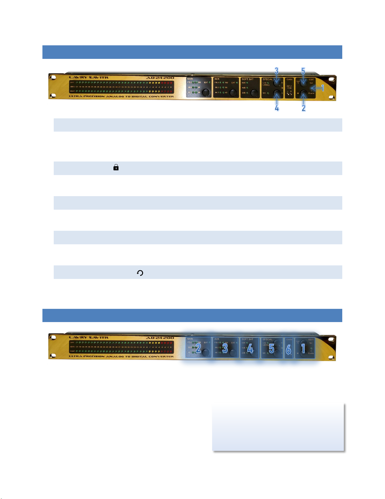
FRONT PANEL (OPERATION MODE)
1. Enable lamp
EDIT mode: ON
OPERATION mode: OFF
2. Enable switch
A sustained press of this switch enables EDIT mode. The ENABLE lamp will turn ON when this change occurs.
3. Mswitch
This switch cycles through the illumination levels of the METER lamps.
4. Sswitch
This switch cycles through the illumination levels of the USER CONTROL SETTINGS groups.
5. Peak Refresh switch
The peak-hold function for the meter can be enabled or disabled by a sustained press of this switch until the
ENABLE lamp flashes once. When enabled; the peak-hold can be reset with a momentary press of this switch.
FRONT PANEL (EDIT MODE)
In EDIT mode, the user-controls are divided into 6 distinct sections, labeled MAIN, AUX, SOFT SAT, SPECIAL, GAIN, and
EDIT.
All User-Control lamps will display one of 4 states:
OFF
ON
Long flash- Pressing Set will turn function On
Short flash- Pressing Set will turn function Off
Conversion continues uninterrupted in EDIT mode.
Operation will only change to new settings after
the SET switch is pressed. This will be followed
by a brief mute of the output.

9
1. EDIT control section
Enable switch
To switch between OPERATION and EDIT mode, press and hold this switch until the ENABLE lamp changes.
In EDIT mode the unit will automatically exit to OPERATION mode after a short idle time.
Enable lamp
EDIT mode: ON
OPERATION mode: OFF
Set switch
This switch executes all changes to audio settings. If SET is not pressed before exiting to OPERATION
mode, then all changes will not be executed and the display will revert to the previous settings.
2. MAIN and
3. AUX control sections
These two sections control clock sources. The control method of each section is identical.
MAIN or AUX switch
Each momentary press selects the next available Sample Frequency option of INTERNAL clock mode.
Each sustained press selects the next available clock mode (INTERNAL, NARROW, WIDE LOCK).
Sample Frequency is automatically detected and selected in EXTERNAL clock modes.
EXT lamp
OFF: INTERNAL clock mode.
ON: EXTERNAL clock mode (NARROW or WIDE LOCK).
Long flash- Pressing Set will select EXTERNAL clock mode (NARROW or WIDE LOCK).
Short flash- Pressing Set will select INTERNAL clock mode.
When both MAIN and AUX are set to Internal and to the same Sample Rate, all digital audio sample
frequency processing is bypassed for the AUX output.

10
SAMPLE RATE lamps
There are 6 lamps labeled with numbers 44.1, 88.2, 96, 176.4, and 192. These refer to sample rates in kHz.
Depending on clock mode, these lamps function differently.
INTERNAL clocking mode
ON: displays the active clock rate.
Long flash- Pressing Set will select this clock rate.
NARROW clocking mode
Narrow Lock Mode offers highest jitter rejection with External Sync.
SEARCHING function (Narrow)
Displays a repeating pattern of single flashing lamps, until a clock signal among the 6 rates
is found.
LOCKED (Narrow)
A single Sample Rate Lamp (ON): displays the locked rate.
WIDE LOCK clocking mode
Wide Lock Mode allows lock to non-standard Sample Rates.
SEARCHING function (WIDE)
Displays a repeating pattern of paired flashing lamps, until a clock signal between 32 and
200 kHz is found.
LOCKED (WIDE)
Paired lamps (ON) indicates the range of the locked frequency:
44.1 and 48 (ON) : 32-68kHz
88.2 and 96 (ON): 68-136kHz
176.4 and 192 (ON): 136-200kHz

11
4. SOFT SAT control section
SOFT SAT switch
This switch will SELECT a SOFT SATURATION level.
3 lamps
These lamps indicate and control application of 4 levels of SOFT SATURATION to the audio signal:
OFF: No Saturation.
ON: Displays level of SOFT SATURATION.
Short flash all three lamps- Pressing Set will select NO SOFT SATURATION.
Long flash- Pressing Set will select this setting for SOFT SATURATION.
5. SPECIAL control section
Low Latency control
Switch
This switch SELECTS between BEST-QUALITY and LOW LATENCY modes.
Lamp
OFF: BEST-QUALITY mode.
Long flash- Pressing Set will select LOW LATENCY mode.
ON: LOW LATENCY mode.
Short flash- Pressing Set will select BEST-QUALITY mode.
MX control
The MX transformation is a proprietary technology, reducing the perceived harsh distortions due to signal
clipping (exceeding the allowed signal level range).
Switch
This switch SELECTS between NEUTRAL and MX modes.
Lamp
OFF: NEUTRAL mode.
Long flash- Pressing Set will select MX mode.
ON: MX mode.
Short flash- Pressing Set will select NEUTRAL mode.

12
6. GAIN control section
INPUT TRIM potentiometers
The L and R potentiometers control INPUT GAIN for the LEFT and RIGHT analog channels.
Using a small, flat-head screwdriver: CLOCKWISE rotation INCREASES GAIN. These trim
pots provide 0-7dB of GAIN. Adjustment may require many rotations.
FULL-SCALE signal for BALANCED inputs is 24dBu. The trim potentiometers provide up to 7dB of
internal GAIN to accommodate lower level input signals.
FULL-SCALE signal for UNBALANCED inputs is 20dBu. The trim potentiometers provide up to 3dB of
internal GAIN to accommodate lower level input signals.
13
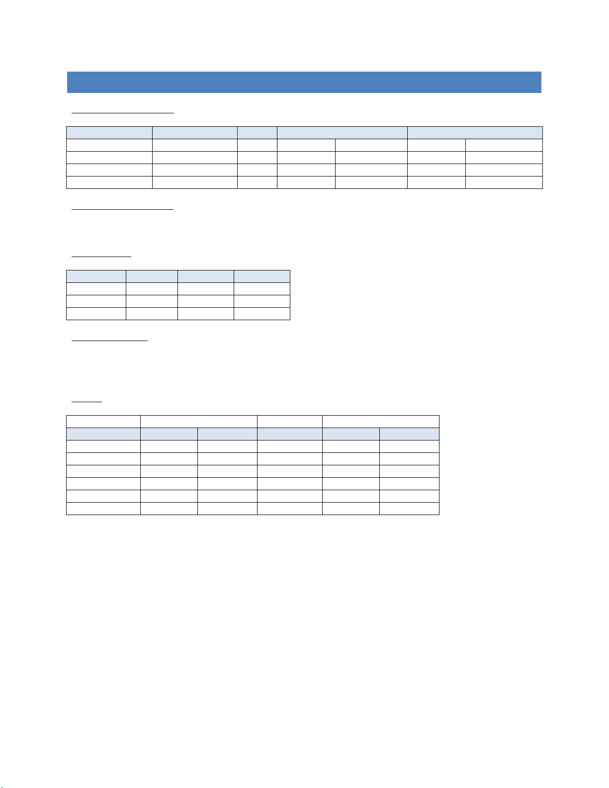
TECHNICAL SPECIFICATIONS
THD+N (0 dB Internal Gain)
Analog Input Level
Source Frequency
Gain
20 kHz Bandwidth
40 kHz Bandwidth
-1 dBFS
1 kHz
0 dB
-110 dBFS
0.00032 %FS
-107 dBFS
0.00045 %FS
-0.1 dBFS
20 Hz to 20 kHz
0 dB
-109 dBFS
0.00035 %FS
-103 dBFS
0.00071 %FS
-1 dBFS
20 Hz to 20 kHz
0 dB
-109 dBFS
0.00035 %FS
-106 dBFS
0.00050 %FS
-3 dBFS
20 Hz to 20 kHz
0 dB
-113 dBFS
0.00022 %FS
-110 dBFS
0.00032 %FS
THD+N (with Internal Gain)
6 dB of Internal Gain: Increases THD+N by less than 2dB of the values above.
Dynamic Range
Sample Rate
Bandwidth
Unweighted
A-Weighted
44.1 kHz
20 kHz
126 dBFS
128 dBFS
96 kHz
40 kHz
122 dBFS
128 dBFS
192 kHz
80 kHz
104 dBFS
128 dBFS
Channel Separation
1 kHz: 123dBFS
20-20 kHz: 108dBFS
Latency
Main Output
AUX Output
Conversion Rate
Best Quality
Low Latency
Auxiliary Rate
Best Quality
Low Latency
44.1 kHz
471 µs
153 µs
44.1 kHz
3.7 ms
3.5 ms
48 kHz
440 µs
150 µs
48 kHz
3.4 ms
3.4 ms
88.2 kHz
267 µs
109 µs
88.2 kHz
1.9 ms
1.7 ms
96 kHz
249 µs
103 µs
96 kHz
1.7 ms
1.6 ms
176.4 kHz
137 µs
89 µs
176.4 kHz
940 µs
890 µs
192 kHz
130 µs
86 µs
192 kHz
865 µs
820 µs

14
APPENDIX A- AC POWER, POWER CORD, AND FUSE ACCESS
1. AC Power and Power Cord
The Lavry Savitr AD-24-200 power supply accepts AC power in the range of 90-264 Volts at 47-63
Hertz. The power supply adjusts automatically for proper operation with AC power within this
voltage & frequency range.
The power for the Savitr is controlled by the rear panel power switch.
The included power cord has a push-button locking feature. Once inserted, you must press the
yellow button to remove the power cable!
2. Accessing the Fuses
The Savitr has two fuses located in the Power Entry Module (PEM).
The following procedure will provide the information needed to access the fuses in your Savitr.
The Savitr requires two 1.25A Time Delay (Slow Blow) 250V 5mm x 20mm fuses. They are located in
the
fuse tray
of the PEM.
The fuse tray is held in the PEM by two small spring-loaded plastic tabs, which must be pressed
with a small screwdriver to release. The top tab must be pressed downward and the bottom tab
must be pressed upward. If possible, use two small screwdrivers to press both tabs at the same
time.
Here is an illustration of the rear panel:
The AC power cord must be removed before attempting to access the fuses!
Always replace the fuses with the recommended type and use the same value for both fuses!

15
WARRANTY
Subject to the conditions set forth below, for one year after the original purchase date of the product, Lavry Engineering
will repair the product free of charge in the United States in the event of a defect in materials or workmanship.
Lavry Engineering may exchange new or rebuilt parts for defective parts. Please call the factory for an RMA number
prior to shipment. No product will be accepted for warranty service without a pre-issued RMA number.
This warranty is extended only to an original purchaser of the product from Lavry Engineering, or an authorized reseller
of Lavry Engineering. Products that are purchased from unauthorized resellers do not have any warranty coverage. A
valid purchase receipt or other valid proof of purchase will be required before warranty service is provided. This
warranty only covers failures due to defects in materials or workmanship and does not cover damages which occur in
shipment or failures resulting from accident, misuse, line power surges, mishandling, maintenance, alterations and
modifications of the product, or service by an unauthorized service center or personnel. Lavry Engineering reserves the
right to deny warranty service to products that have been used in rental, service bureau, or similar businesses.
This limited warranty gives you specific legal rights. You may have others which vary from state/jurisdiction to
state/jurisdiction.
LIMITS AND EXCLUSIONS
LAVRY ENGINEERING DOES NOT, BY VIRTUE OF THIS AGREEMENT, OR BY ANY COURSE OF PERFORMANCE, COURSE OF
DEALING, OR USAGE OF TRADE, MAKE ANY OTHER WARRANTIES, EXPRESS OR IMPLIED, INCLUDING, WITHOUT LIMITATION,
ANY WARRANTY OF MERCHANTABILITY, FITNESS FOR A PARTICULAR PURPOSE, TITLE OR NONINFRINGEMENT, AND ALL
SUCH WARRANTIES ARE HEREBY EXPRESSLY DISCLAIMED. LAVRY ENGINEERING EXPRESSLY DISCLAIMS ANY IMPLIED
INDEMNITIES. LAVRY ENGINEERING SHALL NOT BE LIABLE FOR ANY INDIRECT, INCIDENTAL, CONSEQUENTIAL, PUNITIVE,
SPECIAL OR EXEMPLARY LOSSES OR DAMAGES, INCLUDING, WITHOUT LIMITATION, DAMAGES TO RECORDINGS, TAPES
ORDISKS, DAMAGES FOR LOSS OF BUSINESS PROFITS, BUSINESS INTERRUPTION, LOSS OF BUSINESS INFORMATION,
LOSS OF GOODWILL, COVER, OR OTHER PECUNIARY LOSS, ARISING OUT OF OR RELATING TO THE USE OF THE PRODUCT,
OR ARISING FROM BREACH OF WARRANTY OR CONTRACT, NEGLIGENCE, OR ANY OTHER LEGAL THEORY, EVEN IF LAVRY
ENGINEERING HAS BEEN ADVISED OF THE POSSIBILITY OF SUCH LOSSES OR DAMAGES. ANY DAMAGES THAT Lavry
ENGINEERING IS REQUIRED TO PAY FOR ANY PURPOSE WHATSOEVER SHALL NOT EXCEED THE ORIGINAL COST PAID TO
LAVRY ENGINEERING FOR THE APPLICABLE PRODUCT. BECAUSE SOME STATES/JURISDICTIONS DO NOT ALLOW THE
EXCLUSION OR LIMITATION OF LIABILITY FOR CONSEQUENTIAL OR INCIDENTAL DAMAGES, THE FOREGOING LIMITATION
MAY NOT APPLY TO YOU.
Table of contents


 user guide")


