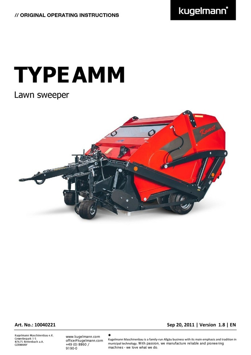
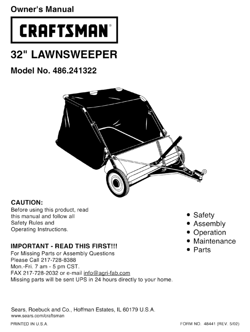
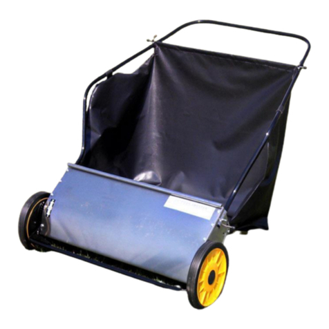
Lawn Tender SW380LT User manual

L-1902-A
OWN E R ’ S
MANUAL
MODEL:
SW380LT
Important:This instruction contains information for the safety
of persons and property. Read it carefully before assembly
and operation of the equipment!
L-1902-A
38” LA W N SWEEPER

L-1902-A
CONGRATULATIONS on your the purchase of your new
LAWNTENDER™ Lawn Sweeper! Your lawn sweeper is designed,
engineered and manufactured to give you the best possible
dependability and performance.
CUSTOMER RESPONSIBILITIES
Please read and retain this manual. The instructions enables you to
assemble and maintain your lawn sweeper properly. And please, always
observe the "Safety" instructions.
TABLE OF CONTENTS
SAFETY............................................................................... 2-3
PARTS REFERENCE .......................................................... 4
PARTS LIST......................................................................... 5
ASSEMBLY.......................................................................... 6-13
FREQUENTLY ASKED QUESTION .................................... 14
SERVICE ............................................................................. 14
WARRANTY......................................................................... BackCover
PRODUCT IDENTIFICATION
PRODUCT COMPATIBILITY
This lawn sweeper is designed for use with lawn tractors & lawn and
garden tractors.
RECORD PURCHASE INFORMATION
Record your purchase information in the spaces provided below.
DATE OF PURCHASE:
COMPANY NAME:
COMPANY PHONE:
SERIAL NUMBER:
2.

L-1902-A
TO HELP PREVENT BODILY INJURY DUE TO LOSS OF
STABILITY OR CONTROL.
Do not exceed maximum towing capacity of towing vehicle
listed in the vehicle operator's manual.
Do not exceed 5 mph.
Do not tow this machine behind a motor vehicle such as a
car, truck or ATV.
Do not tow this machine behind a ZTR (Zero Turn Radius)
Mower.
SAFETY
Read the general safety operating precautions in your
towing vehicle operator's manual for additional safety
information.
Operate Safely
Use this machine for intended purpose only.
This machine is intended for use in lawn care and home
applications. Do not tow behind a vehicle on a highway or in
any high speed applications. Do not tow at speeds higher
than maximum recommended towing speed.
Towing speed should always be slow enough to maintain
control. Travel slowly over rough ground.
Do not let children or an untrained person operate machine.
Do not let anyone, especially children, ride on this machine
or the towing vehicle. Riders are subject to injury such as
being struck by foreign objects and being thrown off. Riders
may also obstruct the operator's view, resulting in this
machine being operated in an unsafe manner.
Check towing vehicle brake action before you operate.
Adjust or service brakes as necessary.
Keep all parts in good condition and properly installed. Fix
damaged parts immediately. Replace worn or broken parts.
Replace all worn or damaged safety and instruction decals.
Do not modify the machine or safety devices. Unauthorized
modifications to the towing vehicle or machine may impair its
function and safety, and void the warranty.
Keep all nuts, bolts and screws tight.
TOWING SAFELY
Stopping distance increases with speed and weight of
towed load. Travel slowly and allow extra time and distance
to stop.
Total towed weight must not exceed limits specified in
towing vehicle operator's manual.
Excessive towed load can cause loss of traction and loss of
control on slopes. Reduce towed weight when operating on
slopes.
Never allow children or others in or on towed equipment.
Use only approved hitches. Tow only with a machine that
has a hitch designed for towing. Do not attach this machine
except at the approved hitch point.
Follow the manufacturer's recommendations for weight
limits for towed equipment and towing on slopes. Use
counterweights or wheel weights as described in the towing
vehicle operator's manual.
Do not turn sharply. Use additional caution when turning or
operating under adverse surface conditions. Use care
when reversing. To avoid jack-knifing, do not allow towing
vehicle wheels to contact drawbar.
Do not shift to neutral and coast downhill.
Protect Bystanders
Keep bystanders away when you operate this machine
Before you back look carefully behind for bystanders.
Before you operate any feature of this machine, observe
your surroundings and look for bystanders.
Keep Riders Off Towed Attachment
Keep riders off towed attachment.
Riders on a towed attachment are subject to injury, such as
being struck by objects and being thrown off the attachment
during sudden starts, stops and turns.
Riders obstruct the operator's view, resulting in the
attachment being used in an unsafe manner.
Keep riders off of hitch bracket.
Keep Body Parts From Under Drawbar
Before you disconnect this machine from towing vehicle
hitch plate:
• Stop on level ground.
• Stop towing vehicle engine.
• Lock towing vehicle park brake.
• Block wheels of the machine.
• Make sure body parts are not under drawbar.
3.

L-1902-A
PARTS REFERENCE
Tools Required for Assembly:
Adj” Wrench (2)
Cross-Tip Scrw Driver
Pliers
Safety Glasses
1
2
2
3
3
9
9
9
5
6
7
75 59
59
26
26
76
11
11 12
74
46
45
42 43
44
40
20
10
41
15
17
18
19
29
28
29
21
22
23
24
27
16
16
16
72
62
33 32
30
30
66
29
29
24
39 16
16
39
31
38
69
63
34
73
35
74
75
29
29
36
37
76
25 50
51
65
52
54 54
53
58
57
56
53
55
61 64
67
37
61
60
75
71 70
71
70
68
48
13
74
74
14
77
47
47
49
8
4
4.

L-1902-A
PARTS LIST
REF PART NO DESCRIPTION QTY.
NO.
1. N-100 Hamper Rope 1
2. N-101 Vinyl Cap 2
3. N-102 Rear Hamper Frame Tube 2
4. N-103 Big Frame Strap 1
5. N-104 Hamper Support Rod 2
6. N-105 Hamper Bag 1
7. N-106 Lower Hamper Frame LH 1
8. N-107 Upper Hamper Frame LH 1
9. N-108 Hex Bolt, M8x16 6
10. N-109 Angle Bracket 1
11. N-110 Bag Arm Tube 1
12. N-111 Lower Hamper Frame RH 1
13. N-112 Hex Bolt, M8x40 2
14. N-113 Upper Hamper Frame RH 1
15. N-114 Height Adjust Grip 1
16. N-115 Lock Nut M6 14
17. N-116 Height Adjustment Handle 1
18. N-117 Carriage Bolt M8x30 1
19. N-118 Brush Shaft 1
20. N-119 Brush 4
21 N-120 Wrapper 1
22. N-121 End Plate RH 1
23. N-122 Pinion Gear RH 1
24. N-123 Dust Cover Assembly 2
25. N-124 Height Adj.Tube Assy 1
26. N-125 Clevis Pin Ø6x37 4
27. N-126 Wing Knob 1
28. N-127 Star Washer Ø8 1
29. N-128 Hex Lock Nut M 12
30. N-129 Slotted Pan Hd Screw M5x12 14
31. N-130 Retainer Brush (Large) 4
32. N-131 Height Adjustment Strap 1
33. N-132 Hitch Tube (RH) 1
34. N-133 Hitch Bracket 1
35. N-134 Hitch Bracket, Straight 1
36. N-135 Hitch Tube (LH) 1
37. N-136 Flat Washer Ø10 4
38. N-137 Hex Bolt M10x85 2
39. N-138 Nylon Lock Nut M5 18
40. N-139 Rear Support Brace 1
41. N-140 Hex Bolt M6x12 2
42. N-141 Dust Cover Retainer 2
43. N-142 Inside Star Washer 2
44. N-143 Brush Shaft Bushing 2
45. N-144 Spacer Bushing Ø16x3mm 2
46. N-145 Spacer for Axle 2
47. N-146 Cross Slot Screw 4
48. N-147 Star Washer Ø5 4
49. N-148 Clevis Pin C 2
50. N-149 End Plate LH 1
51. N-150 Special Washer 2
52. N-151 Bushing 2
53. N-152 Retaining Ring 4
REF PART NO DESCRIPTION QTY.
NO.
54. N-153 Adj. Washer A 4
55. N-154 Adj. Washer C 2
56. N-155 Dowel Pin (Drive) 1
57. N-156 Pinion Gear (LH) 2
58. N-157 Adj. Washer B 2
59. N-158 Pin, Clevis " 2
60. N-159 Wheel &Tire Assy 2
61. N-160 Wheel Bushing 4
62. N-161 Hex Bolt M8x65 2
63. N-162 Hex Bolt M8x50 2
64. N-163 Hub Cap 2
65. N-164 Hex Bolt M6x35 4
66. N-165 Spacer Bushing Hgt Adj Strap 1
67. N-166 Nylon Lock Nut M10 2
68. N-167 Hex Bolt M5x25 4
69. N-168 Big Flat Washer Ø8 2
70. N-169 Hex Bolt M6x20 8
71. N-170 Retainer Brush 8
72. N-171 Hitch Pin 1
73. N-172 Tube, Hitch Spacer 3
74. N-173 Hair Pin Cotter Ø3 5
75. N-174 Hair Pin Cotter Ø2 4
76. N-175 Clevis Pin B 2
77. N-176 Hex Lock Nut 4
5.

L-1902-A
Step 1. ASSEMBLE BRACKET TO SWEEPER HOUSING
9
33
29
25
10
1a) Assemble the angle bracket (10)to the
sweeper housing using a M8x16 hex bolt (9) and
a M8 hex lock nut (29).
IMPORTANT: Make sure the bracket is turned as
shown and aligned straight with the housing and
then tighten.
1b) Cut off the plastic tie that holds the height
adjustment tube (25) in place
Step 2. ASSEMBLE L/R TUBE HITCH
65
16`
2a) Assemble the R.H. Hitch Tube (33) to the
sweeper housing using M6x35 Hex Bolt (65) and
M6 Lock Nut (16).
Do not tighten yet. Repeat for the L.H. hitch tube
(2).
Step 3. JOIN HITCH TUBES
29
62
3a) Fasten the hitch tubes together using two
M8x65 Hex Bolts (62) and M8 Lock Nuts (29). Do
not tighten yet.
6.

L-1902-A
Step 4. ASSEMBLE & ATTACH HITCH BRACKETS
34
35
73
74
29
63
72
NOTE: If your tractor hitch has a ground
clearance between 11 in. and 13 in., see
illustration A. If your tractor hitch ground clearance
is between 8 in. and 11 in., see illustration B.
4a) Assemble the hitch brackets (34) and (35) to
the hitch tubes using two M8x50 hex bolts (63)
and M8 hex lock nuts (29). The bolts should
straddle the front hitch tube bolt. Do not tighten
yet.
4b) Tighten the four bolts fastening the hitch
tubes to the sweeper housing installed in Step 2.
4c) Tighten the two
bolts fastening the ends of the hitch tubes
together installed in Step 3.
Tighten the two bolts fastening the hitch
brackets to the hitch tubes installed in Step 4a.
4d) Assemble the hitch pin (72), three spacers
(73) and the hair cotter pin (74) to the hitch
brackets.
34
35
73
74
29
63
72
7.

L-1902-A
Step 5. ATTACH HEIGHT ADJUSTMENT HANDLE
29
29
25
5a) Attach the height adjustment handle (17) to
the height adjustment tube (25) as shown. Use
two M8×40 hex bolts (13) and M8 lock nuts (29).
Do not tighten yet.
5b) Attach the height adjustment grip (15) onto the
height adjustment handle (17).
Step 6. ATTACH ADJUSTMENT HANDLE
STRAP
69
66
10
32
9
17`
13`
15`
6a) Insert a M8 x16 hex bolt (9) through the angle
bracket (10). Assemble onto the bolt (in order) the
spacer bushing (66), the height adjustment strap
(32), a Ø8 big flat washer (69) and a M8 hex lock
nut (29), then tighten.
Step 7. CONNECT ADJUSTMENT STRAP
TO HANDLE
69
18
17
28
32
27
7a) Position the height adjustment (17) handle
side to side so that the star washer (28) can fit
between the handle and the height adjustment
strap (32). Tighten the nuts securing the height
adjustment handle, installed in Step 5a.
NOTE: Star Washer must be inserted between
the height adjustment handles and height
adjustment strap in order to properly operate the
sweeper height adjustment feature.
7b) Insert the M8×30 carriage bolt (18) through
the height adjustment handle (17). Assemble onto
the bolt, in order, the height adjustment strap, star
washer (28), a big flat washer (69) and the wing
knob (27).
8.

L-1902-A
Step 8. ASSEMBLE HAMPER
14
3
3
4a) Turn rear hamper frame tube (3) so that the
brace holes in the middle of the tube face down.
Slide the tube through the two loops sewn into the
top rear seam inside the hamper bag.
Step 9. ATTACH UPPER HAMPER TUBES
TO REAR HAMPER TUBE
47
9a) Insert the left upper hamper frame tube (8)
and the right upper hamper frame tube (14)
through the stitched flaps on each side of the
hamper bag.
9b) Attach the ends of the rear hamper
tube (3) onto the ends of the upper hamper
frames tubes using 1/4” x 1-1/4” Hex bolt and lock
nut combination (47) and tighten.
Step 10. ATTACH LOWER HAMPER TUBES
TO REAR HAMPER TUBE
47
10a) Turn the second rear hamper tube (3) so
that the brace holes in the middle of the tube face
up.
10b) Assemble the ends of the rear hamper tube
onto the ends of the left lower hamper frame tube
(7) and right lower hamper frame tube (12).
Fasten together using 1/4” x 1-1/4” Hex bolt and
lock nut combination (47) and tighten.
3
12
holes facing
downward
9.

L-1902-A
Step 11. ATTACH HAMPER FRAME TO BAG
74 49
11a) Place the assembled lower hamper tubes,
in to the bottom of the hamper bag.
11b) Attach the end of the RH lower hamper
frame tube (12) to the outboard side of the RH
upper frame tube (14) using a clevis pin (49)
inserted from the inside and secure in place with a
hair cotter pin (74), as shown.
11c) Repeat for LH side.
12`
14`
Step 12. ATTACH HEIGHT ADJUSTMENT HANDLE
76
75
12a) Insert the bag frame strap (4) in to the
stitched sleeve along the front edge of the bag
bottom.
12b) Attach the bag frame strap (4) to the lower
hamper side tubes using two clevis pins (76) and
two hair Ø2 cotter pins (75).
4
10.

L-1902-A
Step 13. SECURE BAG TO HAMPER FRAME
53
13a) Secure the bag corners around the lower
hamper frame tubes by snapping the bag flaps to
the bag bottom on both sides
Step 14. INSERT HAMPER SUPPORT RODS
IMPORTANT: Do not over bend the support rods
during this step. Over bending will cause the steel
rods to lose supporting tension.
14a) Tip the hamper onto it’s back and insert the
two hamper support rods (5). Place the ends the
hamper support rods in to the two holes locate in
the center of the upper and lower rear hamper
tubes (3). Bend the rods just enough to fit into the
holes in the tubes.
11.

L-1902-A
Step 15. INSERT HOLES IN STITCHED FLAPS
15a) Feel along the stitched flap on the hamper
bag to locate the lower hole in each upper hamper
frame tube. Place a hole through both sides of the
stitched flaps in alignment with the lower hole.
Step 16. ATTACH BAG ARM TO HAMPER
49 74
11
16a) Insert a clevis pin (49) through the lower
hole in each upper hamper frame tube.
16b) Attach a bag arm tube (11) on to each clevis
pin (49) and secure it with a hair cotter pin (74).
16c) Slid a vinyl cap (4) on to the end of
each bag arm tube.
4
UPPER
HOLE
LOWER
HOLE
UPPER
FRAME TUBE
12.

L-1902-A
Step 17. SECURE BAG TO HAMPER FRAME
1
3
13a) Secure the bag corners around the lower
hamper frame tubes by snapping the bag flaps to
the bag bottom on both sides
Step 18. ATTACH ROPE
18a) Secure the rope (1) to the top center of the
upper rear hamper tube (3) of the hamper bag
frame.
11
76
75
3
Step 19.ATTACH HAMPER BAG TO SWEEPER
18a) Assemble the hamper bag (6) to the
sweeper by sliding the ends of the bag arm tubes
(11) into the ends of the sweeper’s hitch tubes
(33) and (36), then secure each with a clevis pin
(76) and hair cotter pin (75).
13.

L-1902-A
14.
FREQUENTLY ASKED QUESTIONS
Sweeper does not pick up:
1. The adjustment lever is set too low. A sweeper is not a dethatcher and
cannot pull thatch, embedded needles or leaves from deep in the
grass. The adjustment height should be set to the height of the mower
deck blades.
2. The adjustment lever is set too high. Lower the adjustment lever.
3. There is a problem with the drive system. See the "Sweeper Wheels"
section.
Grass goes over the top of the Hamper:
1. Forward speed is too fast. Slow the towing vehicle down. Best speed is
3 mph or less. (3 mph = 40 feet in 9 seconds).
2. Wind screen can be used to break wind coming over the top of the
hamper. Slower forward speeds must be used when using the wind
screen.
Sweeper Wheels....Not moving... Skip...Lock-up:
1. The brush is not turning or stops turning. The adjustment lever is set too
low. Measure the cut height of the mower. Set the brush height to sweep
the same as the cut height.
Hamper drags the ground:
1. The tow bars are not horizontal to the ground when attached to the tow
vehicle Remove the clevis and reinstall in a different set of holes. The
clevis can be turned over to get additional adjustment. See Step 4 on
attaching the hitch brackets
SERVICE
Do not allow material to remain in the hamper for extended periods of
time. Clean the hamper using a water hose and allow to dry prior to
storage.
Check all moving parts for wear and freedom of movement.
Routine lubrication of the pinion and dowel pin is required. We
recommend in the fall before storage as a minimum. Remove, clean
and lubricate the dowel pin (56) inside the drive pinions (23 & 57) with a
light oil such as WD40, 3 in1, or similar. Do not use motor oil or grease.
Check the drive pinions for wear. These are considered normal wear
parts. Contact our Customer Service Department to purchase
replacement drive pinions, see parts reference.
Lubricate the wheels annually with multipurpose grease.
Check all fasteners for tightness.
Inspect for rust on painted surfaces. Sand lightly and touch up
damaged areas with enamel paint.
GETTING QUALITY SERVICE
Quality Continues with Quality Service
We provide a process to handle your questions or problems. Follow the
steps below to get answers to any questions you may have about your
product.
1. Refer to your attachment and machine operator manuals.
2. In North America or Canada, call 1-866-997-0009 and provide
product serial number and model number.

L-1902-A

L-1902-A
“Lawntender” warrants the products listed below against defects in
material and workmanship, and will at its option, repair or replace, free
of charge, any part found to be defective in materials or workmanship.
This limited warranty shall only apply if this product has been
assembled, operated, and maintained in accordance with the
information furnished with the product, and has not been subject to
misuse, abuse, commercial use, neglect, accident, improper
maintenance, alteration, vandalism, theft, fire, water, or damage
because of other peril or natural disaster.
Normal Wear Parts or components thereof are subject to separate
terms as follows: All normal wear parts or component failures will be
covered on the product for a period of 90 days. Wheels and tires are
considered normal wear parts.
Parts found to be defective within the warranty period will be replaced
at our expense. Our obligation under this warranty is expressly
limited to the replacement or repair, at our option, of parts found to be
defective in material and workmanship.
HOW TO OBTAIN SERVICE: Warranty parts replacements are
available, ONLY WITH PROOF OF PURCHASE, through our
Customer Service Department. Call 866-997-0009, or visit our
website at www.brinly.com
This limited warranty does not provide coverage in the following
cases:
a) Routine maintenance items such as lubricants.
b) Normal deterioration of the exterior finish due to use or
exposure.
c) Transportation and/or labor charges.
d) Commercial and/or rental use.
No other warranty, including any implied warranty of
merchantability of fitness for a particular purpose, applies. No
other express warranty whether written or oral, except as
mentioned above, given by any person or entity, including a
dealer or retailer, with respect to any product, shall bind
Lawntender. During the period of the warranty, the exclusive
remedy is repair or replacement of the product as set forth
above.
In no event shall recovery of any kind be greater that the amount of
the purchase price of the product sold. Alteration of safety features of
the product shall void this warranty. You assume the risk and liability
for loss, damage, or injury to you and your property and/or to others
and their property arising out of the misuse or inability to use this
product.
This limited warranty shall not extend to anyone other than the original
purchaser or to the person for whom it was purchased as a gift.
IMPORTANT: The Warranty period stated below begins with the
PROOF OF PURCHASE. Without the proof of purchase, the
Warranty period begins from the date of sale to the retailer or dealer.
SWEEPER WARRANTY PERIOD:
The warranty period for this lawn Sweeper is as follows: Steel Frame
parts, Hamper, and Axle & Bearings – 1 Year. Tires, Wheels , Pinion
Gears and Brushes – 90 Days (wear parts).
MANUFACTURER’S LIMITED WARRANTY
Table of contents