LawnMaster PBT4346T Operating and installation instructions

WARNING: Read the instructions before using the product
Before initial start-up, please read through these operating instructions carefully
prior to using the machine. Keep the instructions safe and pass them on to any
subsequent user so that the information is always available.
PBT4346T
L951151
Serial Number:
Translation of the original instructions for use
Petrol brush cutter

2
Contents
Intended use
Safety information
Symbols
General description
Assembly
Operation
Maintenance and service
Troubleshooting
Storage
Disposal / environmental protection
Guarantee
Technical specifications
CE
2
3
3
8
10
13
18
25
29
30
31
31
32
33
CONTENTS

3
When the nylon head is used, the brush cutter is suitable for cutting grass in the garden, along
border edges and around trees or fence posts. When the metal cutting blade is used, the
equipment cuts grass, weeds or light plant growth. The equipment is intended exclusively for
private use.
Any other use not explicitly authorized in these instructions may result in damage to the
equipment and represent a serious hazard to the user. The equipment is not designed for cutting
bushes, small trees or similar plants. The equipment is intended for use by adults. Young people
over the age of 16 may usethe equipment only under supervision. The operator or user is
responsible for accidents or damage to other people or their property. The manufacturer is not
liable for damages caused by use other than for the intended purpose or by incorrect operation.
In order to be able to operate the equipment safely, all instructions and
information in the operating instructions about safety, assembly and
operation must be followed precisely. Anyone operating or maintaining
this equipment must be familiar with the operating instructions and
informed of potential hazards.
Do not allow access by children or by people who are ill or infirm. Children must be carefully
supervised when they are in the area of machinery. Observe the regional and local accident
prevention regulations applicable where you are. The same applies for all regulations concerning
occupational safety and health in the workplace. The manufacturer cannot be held liable if the
machines produced by the same are modified without permission and if damage to people or
property occurs as a result of such modifications.
Warning!
Always take basic precautions when using machinery. Please also observe
all tips and information in the additional safety information.
INTENDED USE
SAFETY INFORMATION

4
General Safety Information
1. Observe the surrounding conditions under which you are working. The motorized equipment
produces toxic fumes as soon as the engine is running. These gases may be odourless and
invisible. Therefore, never work with the equipment in enclosed or poorly ventilated spaces.
Ensure adequate ventilation when working. Ensure a safe stance in the wet, snow and ice, on
slopes and on uneven territory.
2. Do not allow strangers to use the equipment. Visitors and onlookers –particularly children and
people who are ill or infirm – must be kept away from the workplace. Prevent other people from
coming into contact with the tools. Do not pass on the equipment to people who are unfamiliar
with the equipment and its handling.
3. Ensure the safe transport and storage of the equipment. Always carry the equipment suspended
by the carrying strap on the tube. Equipment that is not in use must be stored in a dry place as
high up as possible or locked away to be inaccessible.
4. Always use the right tool for any work. E.g. do not use small tools or accessories for work that
should actually be performed with heavy tools. Use tools only for the purposes for which they
have been constructed.
5. Ensure appropriate clothing. Clothing must be appropriate and not impede you when working.
Wear clothing with cut protection pads.
6. Use personal protective equipment. Wear safety boots with steel caps / steel soles and
non-slip soles. Wear a hard hat if there is a risk of falling objects when working.
7. Wear safety goggles. Objects may be thrown out. Serious eye injuries may result.
8. Wear ear protection. Wear personal sound protection, e.g. earplugs.
9. Hand protection. Wear strong gloves – leather gloves offer good protection.
10. Operating the equipment. Never work without the protection on the cutting tool. Risk of injury
from objects being thrown out.
11. Remove the socket wrench etc. All keys or similar must be removed before the equipment is
switched on.
12. Stay alert at all times. Pay attention to what you are doing. Use your common sense. Do not
use motorized tools when you are tired. Work with the equipment must not be carried out under
the influence of alcohol, drugs or medications, which impair reactions.
13. Filling with fuel.
• Always adhere to the current fire regulations and the respective state/federal regulations for
fire prevention.
• Fuel and fuel fumes are highly flammable.
Do not fill with fuel when the engine is running or still hot. When filling up, ensure good
ventilation. Smoking and open flames are prohibited.

5
• Always switch off the engine before filling. Always open the filler cap with care, so any excess
pressure present can be relieved slowly and no fuel sprays out. The work with the equipment
causes high temperatures on the housing. The equipment must therefore be allowed to cool
before filling. Otherwise, the fuel could ignite and cause serious injuries.
• When filling with fuel, ensure that the tank is not overfilled. If liquid misses, this must be
cleared away immediately and the equipment cleaned.
• After filling, ensure that the seal screw is sitting properly in order to prevent it from coming
loose as a result of the vibrations caused during the work.
• Watch out for leaks. Do not start the engine if fuel is leaking. Risk of death as a result
of burns!
14. Usage duration and breaks. Prolonged use of the motorised equipment can cause circulation
disorders in the hands as a result of the vibration. However, the usage duration can be
extended with suitable gloves or regular breaks. Be aware that personal tendency to poor
circulation, low external temperatures and high gripping forces will reduce the usage duration
when working.
15. Be aware of damaged parts. Before initial operation and after severe impacts, check the
equipment for signs of damage and wear. Are individual parts damaged? In case of slight
damage ask seriously whether the tool will nonetheless work properly and safely. Ensure
correct alignment and adjustment of moving parts. Do the parts interlock correctly? Are parts
damaged? Is everything correctly installed? Are all the other requirements in place for proper
functioning? Damaged safety devices etc must be repaired or replaced by authorised people if
there is no explanation otherwise in the operating instructions. Defective switches must be
replaced by an authorized body. If repairs are required, please contact a customer service
centre authorized by us.
16. Always switch off the engine before undertaking adjustments or maintenance work. This
particularly applies for work on the cutting head.
17. Use only authorised parts. In case of maintenance and repair, use only identical spare parts.
Contact the service centre for spare parts.
Warning!
The use of other mowing heads as well as accessories and attachments
that are not explicitly recommended can result in danger to people and
objects. The tool is to be used only for the intended purpose. Any
misappropriation is regarded as improper use. The user alone – and
definitely not the manufacturer – is responsible for property and personal
damage resulting from such improper use.
The manufacturer cannot be held liable if machines from the same are
modified or used improperly and damage occurs as a result.

6
Caution! A certain residual risk, which cannot be eliminated, always remains even
in the case of proper use of the tool. The following potential hazards can be
derived from the type and design of the tool:
• Contact with the unprotected cutting head (cuts).
• Reaching into the scythe when it is running (cuts).
• Hearing damage if no appropriate protection is worn.
• Dust and gas formation that is harmful to health if the equipment is used in enclosed spaces
(nausea).
Additional Safety Regulations
1. Caution! Always keep hands and feet away from the cutting area, particularly
when starting the equipment.
2. Always hold the equipment with both hands on the multifunction handle.
Always keep the equipment at an appropriately safe distance from the body and assume a stable
body position. Always use the carrying strap.
3. Always wear safety goggles.
4. Use the equipment only in daylight or with the option of good artificial lighting.
5. Do not use the equipment in the rain or on damp grass.
6. Before use or after an impact, check the equipment for possible damage; repair if necessary.
7. Do not use the equipment if the safety devices are damaged or not correctly installed.
8. Ensure that the engine ventilation slots, protective cover and cutting device are always free of
dirt or residues.
9. During the work processes, always ensure that there are neither people nor animals within a
radius of at least 15 m. Switch off the equipment immediately if anyone and particularly a child
comes into the range of the machine. When using the equipment, stones and other elements
that can cause serious injuries can be thrown out.
10. When the equipment is in operation, keep away from the moving parts (in the area of the
cutting devices). After switching off, the cutting head continues to turn for a few seconds.
11. Before using the equipment, remove stones, twigs and any other solid material from the
working area. Start the machine only as described in the instructions. It must not be turned
upside down or be in the working position when it is started. Do not cross gravel roads or
paths with the equipment running.

7
Precautions to Prevent Recoil
12. The greatest care is required when extending the cutting thread. Risk of injury from cuts. After
executing these processes, reassume the correct working position before switching on the
equipment.
13. Do not use metallic cutting reels or saw blades. Note that the equipment remains in operation
for a few seconds after the switch is released.
14. Switch off the engine when:
- Refuelling the equipment,
- Not using it,
- Leaving it unattended,
- Cleaning it,
- Transporting it from one location to another,
- Removing or replacing the cutting device and manually adjusting the length of the
cutting thread.
When the metal cutting blade is used, there is a risk of recoil if the blade edge hits an obstacle
(stone, wood).
• Hold the equipment firmly in both hands.
• Ensure that there are no obstacles on the ground and do not use the metal cutting disk near
fences, metal posts or similar.
8
In case of recoil, the user receives a powerful jolt from the motorized
strimmer. This may result in loss of control of the equipment and in
serious injury. Recoil can be avoided by care and correct technique.

8
On the equipment, there are information symbols. These convey important information about the
product or information about its use.
• Caution: Special safety measures are required when handing the equipment!
• The entire operating instructions must be read and understood before use. Nonobservance of the
operating instructions may be fatal!
Warning signs with details for the prevention of personal and property damage.
Command signs with details for the prevention of damage.
Information signs with information for better handling of the equipment.
1. Read the operating instructions carefully before using the
equipment.
2. Wear eye, ear and head protection.
4. Wear safety boots with sturdy soles.
3. Wear protective gloves. Risk of injury from cuts.
5. Maintain a safety distance of min. 15 m from others.
6. Danger from parts being thrown out! Keep away from other people.
Symbols in the Instructions
SYMBOLS
Symbols on the Equipment

9
10. Specification of the guaranteed sound power level LWA in dB.
11. Maximum rotational frequency of the spindle.
12. Conforms to current standards.
13. Mix ratio 40:1, Use ONLY fuel mix
STOPPING
STARTING
14. Symbol on the choke lever
Lever in cold start position (START)
Lever in warm start position (RUN)
9,000
7. Caution! Fuel and fuel fumes are flammable. Risk of fire and
explosion!
X10
8. Caution! Hot surfaces – risk of burns!
9. Symbol on the fuel pump: Press the fuel pump 10x before starting
O
I

10
GENERAL DESCRIPTION
1 Engine housing
2 Fuel tank
3 Starter handle with starter cable
4 Auto-choke knob
5 Air filter cover
6 Ignition cable
7 Muffler
8 Accelerator cable
9 Large cable clamps
10 Anti-vibration ring
11 Bike Handle
12 Handle Adjustment Knob
13 Shaft tube
14 Line cutter
15 Nylon Head Guard
16 Nylon Head
17 Cutting Line Spool
18 Metal cutting blade
19 Gear Housing
20 Metal Blade Guard
21 Small cable clamps
22 Multi-function Control Handle
23 Carry Ring for Shoulder Strap
1
8
9
23
22
21
12
10 11
13
20
19
18 17 16
15
14
4567
32
pic 1

3
11
Functional Description
The manually operated and portable motorized strimmer is driven by a combustion engine, which
operates without interruption during the work.
The power transmission is by means of a clutch disc, which transmits the output to the cutter via a
centrifugal clutch at high speed.
(Picture 1, nos. 15 + 20)
Protects the operator from accidental contact with the cutting tool and foreign
bodies being thrown out.
pic 2
41
40
42
4
Safety Functions
• On/off switch (picture 2, no. 40)
The on/off switch switches off the engine. It must be in position in order to restart the engine.
• Throttle lock (picture 2, no. 41)
Prevents accidental acceleration of the engine. The throttle can be operated only when the
throttle lock is depressed.
• Nylon Head Guard

12
Delivery Contents (Picture 3)
Start by unpacking the equipment and check that it is complete.
• Engine part with shaft tube, cutting head holder, accelerator cable and unfitted multifunction
handle (see picture 1)
15 Nylon Head Guard (including fixings)
16+17 Nylon Head & Cutting Line Spool
18 Metal cutting blade (4 teeth)
20 Metal Blade Guard (including fixings)
24 Allen key
25 Maintenance Locking Pin
26 Maintenance Socket Spanner
27 Fuel mixing can
28 Shoulder Strap
• Instruction Manual
The equipment has an automatic double thread reel as the cutter as well as a metal cutting blade,
which can be fitted optionally.
In the cutting process, two nylon lines or four metal blades rotate about an axis vertical to
the cutting level. To protect the user, the equipment has a protective device, which covers the
cutting device.
Please refer to the descriptions below for how the operating parts work.
pic 3
13
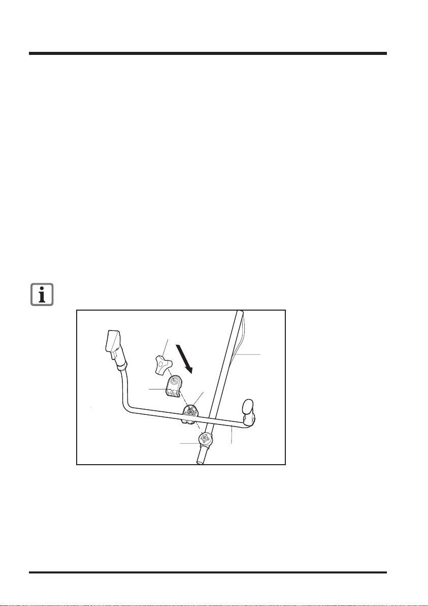
1. Turn counterclockwise to loosen handle adjustment knob (12) and take off top handle
holder (31).
2. Place Bike Handle (11) in the handle slot, close bottom handle holder (29) with top handle
holder (31).
3. Insert handle adjustment knob (12) through handle holder (31, 29), handle base (30), turn
clockwise and fix them firmly.
4. Fix the accelerator cable (8):
With the large cable clamp (9) on the shaft tube (13);
With the small cable clamp (21) on the bike handle (11).
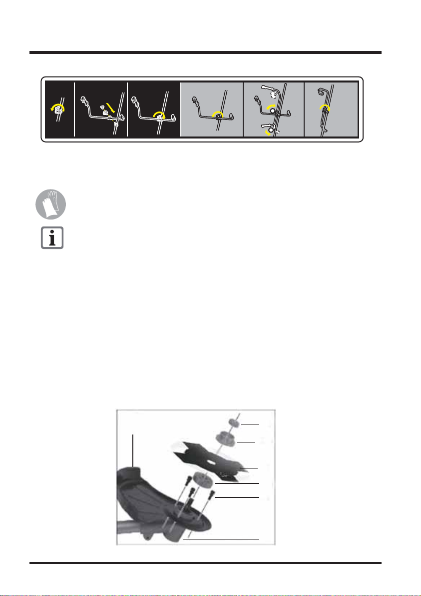
Foldable function of bike handle for easy transportation:
1. Turn counterclockwise several times to loosen tube fixing knob (12);
2. Turn clockwise and fold bike handle (11) to save space.
Before operation of the equipment the equipment must be fully assembled correctly, including
attachment of the shoulder strap.
Check equipment and assembly is correct prior to operation.
Fitting the Handle (Picture 4)
Ensure that the accelerator cable (8) is not twisted or kinked.
ASSEMBLY
31
30
29
12
8
11
pic. 4
Installing/Removing the Metal Cutting Blade
Dismantling the Nylon Head is described in the section on
« Installing/Removing the Nylon Head ».
Wear protective gloves when handling the metal cutting blade.
14
Installing the Metal Blade Guard (picture 5):
1. If applicable, unscrew the top (33b) and bottom (33a) flanges mounted on gear housing (19).
2. Screw the guard (20) onto the gear housing (19) using the 3 screws (34) enclosed.
Installing the metal cutting blade (picture 5):
3. Place the metal cutting blade (18) and flanges (33a+b) on the Gear Housing (19) in the
following order: Bottom flange (33a) – metal cutting blade (18) – top flange (33b).
4. Screw on the metal cutting blade (18) anticlockwise using the fixing nut (35) and with the aid of
the Maintenance Socket Spanner (see picture 2, no. 26).
35
33b
18
pic. 5
20
33a
34
19
1
2

15
Check that the pin is removed from the hole on the gear housing before
starting the engine.
Removing the metal cutting blade (picture 6):
5. To lock the axle, push maintenance locking pin (25) sideways into the hole provided on the
gear housing (19) and on the bottom flange (33a).
6. Unscrew the fixing nut clockwise with the aid of the Maintenance Socket
Spanner (26) and remove the top flange (33b) and the metal cutting blade (18).

16
Installing/Removing the Nylon Head (Picture 7):
Installing the Guard:
1. Screw the Guard (15) onto the Metal Blade Guard (20) using the 3 screws and nuts (36)
enclosed.
Installing the Nylon Head :
2. Screw the Nylon Head (16) anticlockwise onto the cutting head holder by hand, as indicated
in the diagram.
3. Remove the protective cap on the Line cutter (14).
Removing the Nylon Head:
4. Unscrew the Nylon Head (16) clockwise by hand. To make the work easier, the cutting
head holder (19) and bottom flange (33a) can be locked using maintenance locking pin
(25) (see also picture 6).
5. Removing the Guard (15) and replace the protective cap over the line cutter (14).
Dismantling the metal cutting blade is described in the section on
“Installing/Removing the Metal Cutting Blade”.
17
Avoid direct skin contact with petrol and the inhalation of petrol fumes.
Health hazard!
The equipment is fitted with a two-stroke engine and therefore
operated exclusively with a mix of petrol and two-stroke engine
oil in the ratio 40:1.
• Use quality unleaded petrol with an octane rating of at least 91.
• Optimum performance will be achieved with the use of high quality two-stroke engine oil
(FC class) designed specifically for the equipment. If this is not available, use super oil for
air-cooled two-stroke engines.
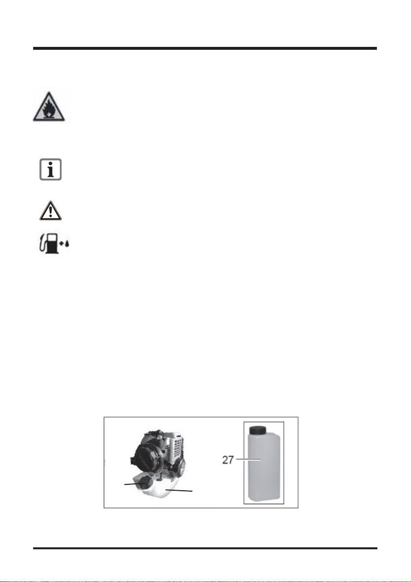
1. Mix petrol and oil in the fuel mixing can (27) included in the delivery: Fill with petrol (gas) up
to the “585.4” mark. Fill with two-stroke engine oil (oil) up to the “600” mark. Close the
container and shake carefully.
2. Unscrew the tank cap (37) and pour the fuel mix into the fuel tank (2). Wipe away fuel residues
around the tank cap and reclose the tank cap.
Filling with Fuel (Picture 8):
Always ensure good ventilation when handling fuel.
Do not smoke when filling with fuel and keep away from any heat sources.
Never fill with fuel when the engine is running. Open the tank cap carefully,
so any excess pressure present can be relieved slowly. Start the equipment
min. 3 m away from the fuel filling location. Risk of fire or explosion in case
of non-observance.
Use only the fuel mix recommended in the instructions. The fuel mix
deteriorates over time. Therefore, do not use fuel mix that is older than 3
months. In case of non-observance, the engine can be damaged and the
guarantee will be invalidated.
2
37
pic 8

18
Observe the following points in particular:
• Check the cutting tools for damage and wear.
• Correct installation of the cutting head
• Easy movement of all switches
• Secure sit of the spark plug connector. If the connector is loose, sparks can be
formed and thus ignite any leaking fuel
• Ensure the handles are clean in order to be able to guide the equipment safely.
• All safety and protective devices must be properly installed and in place before
the equipment can be started.
The nylon head must be able to run freely.
Before starting the equipment, ensure that the nylon head is sitting correctly and that the moving
parts are free.
1. Put on the shoulder strap (28) and close the strap clasp (38).
2. Adjust the strap so it fits tightly.
3. Adjust the strap so the spring clip (39) is around 10 cm below the hip.
4. Fix the spring clip onto the carry ring for shoulder strap (23) on the equipment.
Warning!
If there is any doubt, seek help with the operation of this equipment from a specialist
in an authorised service centre.
Always wear a shoulder strap when working with the equipment. Always
switch off the equipment before loosening the shoulder strap. Risk of
accidents.
Putting on the Shoulder Strap (Picture 9):
Unhook the equipment before starting the engine and fix it to the carrying
strap with the engine running.
Warning!
Before initial operation of the equipment, it must be checked that the condition
is safe for operation. If there is any doubt, do not start the equipment.
Initial Operation
OPERATION

19
1. Fuel
• Level the engine before fueling.
• Open the fuel tank cap and fill the fuel tank with 40:1 gas/oil-mixed fuel.
• Pour slowly to avoid splash back” and allow air to escape from the fuel tank.
• Close the tank cap securely by turning it clockwise as far as it will do.
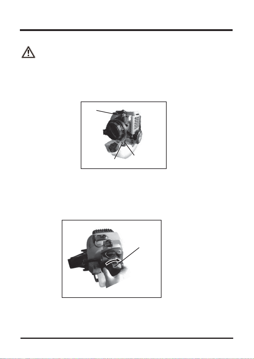
Starting the Engine (Picture 10):
Warning!
Never fill the tank so the fuel level rises into the filler neck. If the tank is
overfilled, heat may cause the fuel to expand and overflow through the
vents in the tank cap. After refueling, make sure the fuel tank cap is closed
securely. If gasoline is spilled on the fuel tank, wipe it off immediately.
Start the engine at least three metres from the filling location
Ensure that the protective cap on the line cutter (see picture 7, no. 14) has
been removed.
3
pic 10
41
40
42
4
20
Note:
• This engine is designed so that overflowed fuel due to pushing a priming pump is to be
returned to the fuel tank.
• There is no fear of flooding the engine, so push the priming pump enough times to get the
engine started.
Move the choke lever to the “START” position.
When the engine is already warm up,set the choke lever to the “RUN” position.
Danger! Exhaust gases contain carbon monoxide, a colorless, odorless,
poisonous gas. Do not operate the engine in enclosed areas. Provide
adequate ventilation at all time.
2. Set the on/off switch (40) on the switching element (22).
3. Move the throttle lever on the equipment to START (engine idle speed) position.
4. Slowly push the priming pump (see picture 1, no. 7) several times until the fuel comes out
of the overflow tube.
5. Choke lever type:
Choke lever
Priming pump
Fuel inlet tube Over flow tube
(transparent)
This manual suits for next models
1
Table of contents
Other LawnMaster Brush Cutter manuals


Popular Brush Cutter manuals by other brands


Cub Cadet
Cub Cadet CC924 Operator's manual

Jonsered
Jonsered GR 2026D Operator's manual

Tonino Lamborghini
Tonino Lamborghini PB 33SB TL Translation of the original operating instructions

Husqvarna
Husqvarna 227R Operator's manual

Briggs & Stratton
Briggs & Stratton NAX 600B manual

HIKOKI
HIKOKI R 36DB Handling instructions


