LawnMaster LMDGJ260H-BC User manual

LMDGJ260H-BC
LMDGJ260H-BK
SAFETY AND OPERATING MANUAL
SPLIT SHAFT
BRUSH CUTTER

2
This manual explains how to operate the Split-Shaft Petrol Brush Cutter. Before operating the unit,
please ensure you read this manual carefully and acknowledge all safety elements before operating.
Understanding how to repair and maintain the unit will help you operate and complete the task safely.
SAFTY FIRST
Instructions in this manual marked with a danger/warning sign, are hazards or concerns that must be
taken into consideration when operating the unit to prevent possible serious injury. Please carefully
read all instructions and operate the unit accordingly.
IMPORTANT
The ‘!’ indicates instructions that must be followed, to prevent mechanical failure, breakdown, or
damage.
NOTE
The notebook indicates helpful tips, hints or directions when using the product.
PREFACE
TABLE OF CONTENTS
Preface 02
Table Of Contents 02
Parts Location 03
Specication 04
Unit Labels 05
For Safe Operations 05
Set-Up 08
Fuel & Chain Oil 10
Operation 11
Maintenance 18
Storage 22
Troubleshooting Guide 23
3
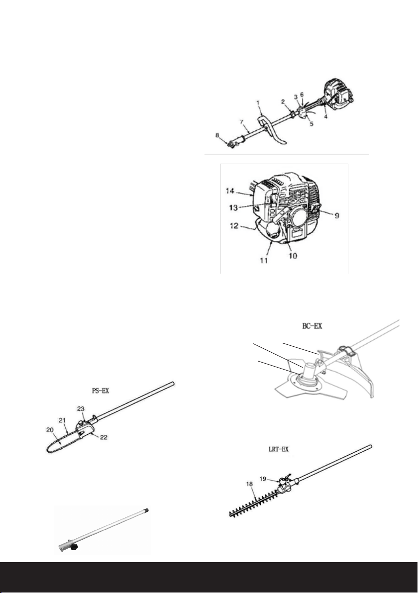
1. PARTS LOCATION
LMDCJ260H-BC
1. Loop handle
2. Shoulder strap hanger
3. On/Off switch
4. Throttle cable
5. Throttle Trigger
6. Throttle set button
7. Drive shaft housing
8. Connector Bolt
9. Spark arrester
10. Starter Handle
11. Fuel tank
12. Primer pump
13. Choke level
14. Air cleaner cover
15. Debris guard
16. Gear case
17. Cutting head
18. Blade
19. Gear case
20. Guide bar
21. Saw chain
22. Chain cover
23. Gear case
LMDCJ260H-HT
LMDCJ260H-PS
POLESAW
HEDGE TRIMMER
Additional Attachments
Can be bought separately or included with the Brush Cutter Kit
LMDCJ260H-BC
15
17
16
LMDCJ260H-E
EXTENSION

4
2. SPECIFICATIONS
MODEL LMDCJ260H-BC
Displacement: 26cc
Max Output: 0.9 kw,7000 r/min
Idle Speed: 2800 + - 200/min-1(rpm)
Fuel: Mixture (Petrol 40: Oil 1)
Spark Plug: Champion RCJ6Y
Fuel Tank Capacity: 0.7L
MODEL BC-EX (BRUSH CUTTER)
Overall Size(L×W×H): 1790×250×310mm
Dry Weight W/O Acc: 5.3kg
Transmission Centrifugal clutch, rigid drive shaft
Reduction Ratio: 1.294
Cutting Head Rotating Direction: Counter-clockwise (Operator view)
MODEL PS-EX (POLE SAW)
Overall Size(L×W×H): 2100×250×310mm
Dry Weight W/O Acc: 5.05kg
Transmission Centrifugal clutch, rigid drive shaft
Reduction Ratio: 0.94
Cutting Head: Counter-clockwise (Operator view)
Sprocket: 7T
Oil Pump: Plunger Type
Type of Chain: 40DL 3/8LP X 0.050”
(ProKut PPGAF20S040DL)
Bar Length: 254mm (10”)
MODEL LRT-EX (HEDGE TRIMMER)
Overall Size(L×W×H): 2300×250×310mm
Dry Weight W/O Acc: 6.1kg
Transmission Centrifugal clutch, rigid drive shaft
Reduction Ratio: 4.0
Cutting head:
Type: Reciprocating Double blade
Tooth: 28 Teeth
Pitch: 30mm
Effective Cut Width: 40mm
Angle Adjust Range: 90 degrees (45 from cutting head
position aligned shaft)
SPECIFICATIONS ARE SUBJECT TO CHANGE WITHOUT NOTICE.
LMDCJ260H-HT
LMDCJ260H-PS
LMDCJ260H-BC

5
Read owner’s manual before
operating this unit.
Wear head, eye and ear protection.
Warning/Attention
Keep all children, bystanders and helpers 15
meters away from the unit.
Do not modify the unit, this will result in the
warranty being void.
Follow the instructions for changing the
accessories. The use of any other accessories
or attachments may cause a potential hazard or
injury to the user, damage to the unit and void this
warranty.
3. LABELS ON THE UNIT
4. SYMBOLS ON THE Unit
Read the manual before operating the unit and keep
the information for future reference to learn safe
operating techniques. For safe operation and
maintenance, symbols are helpful indications and
tips.
The direction to open the choke
Position: AIR CLEANER COVER
(PS-EX Only)
If you turn the rod by screwdriver follow the
MIN & MAX arrow to the “MAX” position,
the chain oil ow more, and if you turn to
the “MIN” position, less.
Position: Bottom of the GEAR CASE
The port to refuel the “MIX PETROL”
Position: FUEL TANK CAP
The direction to close the choke
Position: AIR CLEANER COVER
5. FOR SAFE OPERATION
Read the “Rules for Safe Operation “with care
and follow the instructions in the manual to
operate the unit safely. Read and be thorough
with the basic controls and functions of the unit. It is
important that you know how to stop and to shut off
the engine, and to unhook a harnessed unit quickly.
Do not allow anyone without proper instruction or
training to operate the unit. All operators of the unit
should wear appropriate foot, leg, eye, face and
hearing protection.
Do not rely on the debris shield on the unit to protect
your eyes from thrown objects. Keep the area clear
of bystanders, children and pets. Never allow chil-
dren to operate or play with the unit.
5.1 WORKING CONDITION
1. When using the unit, please ensure you wear
appropriate clothing and safety equipment as listed:
(1) Helmet
(2) Ear Muffs
(3) Protection goggles
(4) Thick work gloves
(5) Non-slip-sole work boots
2. Other important tools and resources to have with
you include:
a) Approved Brush Cutter Attachments
b) Reserve fuel
c) For commercial use, hazard signage and rope to
cordon working area.
d) Whistle (Collaboration or emergency).
3. In addition to head, eye, face and ear protection,
please wear appropriate footwear to protect your
feet and to improve footing on slippery surfaces. Do
not wear open-toed footwear, or go bare foot or bare
legged. Do not wear ties, jewelry, or loose, dangling
clothing which could be caught in the unit.
Do not allow anyone without proper instruction or
training to operate the unit. All operators of the unit
should wear appropriate foot, leg, eye, face and
hearing protection.
Do not rely on the debris shield on the unit to protect
your eyes from thrown objects. Keep the area clear of

6
NOTE
Check and follow local regulations regarding
appropriate sound levels and hours of operations
5.2 WORKING CIRCUMSTANCE
1. Never start the engine inside a closed room or
building. Exhaust fumes contain carbon monoxide
which is a health risk.
2. Never use the product:
(a) When the ground is slippery and you cannot
maintain a steady posture.
(b) At night, fog, or when your vision might be
limited so it becomes dicult to gain a clear view of
your working area.
(c) During storms, rainy weather, and or strong or
gale-force winds. Do not use the unit if the weather
conditions might make it unsafe to operate.
5.3 WORKING PLAN
1. DO NOT use the Brush Cutter under the inuence
of alcohol, exhaustion or lack of sleep. Do not use
the unit if you are unwell or drowsy as a result of
taking medication.
2. When using the brush cutter, allow plenty of
time to rest. Limit your working sessions to 30-40
minutes, and take 10-20 minutes of rest in-between
each working session. Keep the total amount of
work performed in a single day to under 2 hours.
WARNING
1. If you don’t observe the working time, or
working manner when using the Brush Cutter
Repetitive Stress Injury (RSI) could occur.
2. If you feel discomfort, redness and swelling of
your ngers or any other part of your body, seek
medical advice as soon as possible.
3. To avoid noise complaints, in general, operate
product between 8 am and 5 pm on weekdays
and weekends.
5.4 BEFORE STARTING THE ENGINE
1. Do not allow anyone to enter the operating
DANGER ZONE with you. The danger zone is an
area 15 meters in radius (about 16 paces) or 50
feet. Insist that a person near the danger zone
wear eye protection from thrown objects.
2. If the unit must be used where there are unpro-
tected people, operate at a low throttle speed
to reduce the risk of thrown objects.
3. Check the working area to avoid any accidents
such as hitting hidden obstacles i.e., stumps,
stones, cans, or broken glass.
IMPORTANT
• Remove any obstacles before operating the
unit.
• Inspect the unit and check for loose parts and
fuel leakage.
• Make sure cutting attachments are properly
installed and securely fastened.
• Be sure to check whether the debris guard is
rmly attached and in place.
• Always use the shoulder strap. Adjust the
strap for comfort before starting the engine.
The strap should be adjusted so the left hand
can comfortably hold the handlebar grip,
approximately waist high
bystanders, children and pets. Never allow children
to operate or play with the unit.
5.5 STARTING THE ENGINE
1. Keep bystanders and animals at least 15m
away from the operating point. If you are
approached immediately stop the engine.
2. The product is equipped has a centrifugal
clutch mechanism; the cutting attachment
begins to rotate as soon as the engine is
started when the throttle is placed into the
‘start position’.
3. When starting the engine, rstly place the
product on the ground (at clear area). Hold it
rmly in place to ensure that neither the cutting
part nor the throttle comes into contact with
any obstacles when the engine starts.
WARNING
NEVER PLACE THE THROTTLE INTO THE
HIGH-SPEED POSITION WHEN STARTING THE
ENGINE.

7
5.6 USING THE PRODUCT
IMPORTANT
Cut only materials recommended by the
manufacturer to avoid any warranty concerns.
Only use the Brush Cutter on tasks explained in the
manual.
1. Grip the handles rmly with both hands. Place
your feet slightly further than your shoulder
width to distribute weight evenly across both
legs to maintain a steady posture when operat-
ing the unit.
2. Keep the Brush Cutter and the cutting attach-
ment waist low when operating the unit.
3. Maintain the speed of the engine at the level
required to perform cutting work, and never
raise the speed of the engine above the level
necessary.
4. If the unit starts to shake or vibrate. Turn off
the engine and thoroughly check the unit. Do
not use the unit until the trouble has been prop-
erly xed or take it to a service dealer for repair.
5. Keep all parts of your body away from the rotat-
ing cutting attachments and hot surfaces.
6. Never touch the muer, spark plug, or other
metallic parts of the engine while the engine is
in operation or immediately after shutting down
the engine. Doing so could result in serious
burns or electrical shock.
7. Be prepared at all times for any hazardous sit-
uations. Warn adults to keep pets and children
away from the working area. Be careful and
aware if you are being approached as an injury
would occur as a result of ying debris.
8. If someone calls out or otherwise interrupts
you while working, always be sure to turn off
the engine before giving them your attention.
5.7 MAINTENANCE
1. In order to maintain the Brush Cutter in proper
working order, perform regular servicing and
maintenance.
2. Always turn off the engine when performing
any servicing or maintenance.
WARNING
The metallic parts reach high temperatures immedi-
ately after stopping the engine.
3. When replacing cutting attachments or any
other unit parts, including oil or any lubricants,
be sure to use only authorized dealer products.
4. In the event any part must be replaced,
maintenance or repair work not described in
this manual must be performed, contact your
local service dealer for assistance.
5. Do Not use any other attachments other than
the attachments recommended with the unit.
6. Do Not take apart the product or alter it in any
way. Doing so will void warranty and might
result in having an unsafe product that does
not function properly.
5.8 HANDLING FUEL
1. The engine of product is designed to run on
mixed fuel which is highly ammable. Never
store fuel cans or rell the tank near a boiler,
stove, wood re, electrical sparks, welding
sparks, or any other source of heat or re which
might ignite the fuel.
2. Never smoke while operating the unit or
relling with fuel.
3. When relling with fuel, always turn off the
engine and allow it to cool down before
refueling.
4. Wipe spilled fuel completely using a dry rag if
spillage occurs.
5. After refueling, screw the fuel cap tightly and
carry the unit to a spot 3m away from where
it was initially refueled before turning on the
engine.
5.9 TRANSPORTATION
1. When hand-carrying the Brush Cutter, cover
the cutting blades if necessary. Lift the Brush
Cutter and carry it with attention to the blade.
4. After starting the engine, check to make sure
the cutting attachments stop rotating when
the throttle is moved fully back to its original
position. If the cutting attachment continues to
rotate even after the throttle has been moved
fully back, immediately turn off the engine and
take the unit to a service dealer for repair and
service.

8
2. Never transport the product over rough roads
or over long distances by vehicle without re-
moving all fuel from the fuel tank. In doing so,
might result in fuel leaks from the tank during
transport.
6. SET-UP
6.1 MOUNTING ENGINE
1. Push the drive shaft housing towards the clutch
housing and rotate it by hand to check that the
drive shaft is engaged with the gears.
2. Insert the drive shaft housing into the clutch
housing until it bottoms, and aligns the
positioning holes on the clutch housing and the
shaft tube and install the screw. When dicult
to engage, twist the engine slightly.
3. Fasten the clamp securely with two screws.
Tighten the screws gradually by turns.
IMPORTANT
Connecting switch wires, connect the switch wires
between the engine and the main. Pair the wires of
the same colour.
6.2 INSTALLING HANDLE (BC-EX, LRT-EX)
•Install the handle to the shaft tube and clamp at the
location that is comfortable to you. (PS-EX only)
• Insert the grip to the shaft tube.
• Fasten the clamps with screws.
6.3 JOINT ATTACHMENT
• Insert the attachment to the main shaft.
• Tighten the knob bolt securely Set up (BC-EX only)
6.4 INSTALLING DEBRIS GUARD
(1) Screw
(2) Plate
(3) Debris guard
Put the debris guard on the gearbox, attach it with
the 2 screws and hardware provided.

9
6.5.1 BALANCE UNIT
1. Put on the Brush Cutter strap and attach the
unit to the strap.
2. Slide clamp up or down until the unit balances
by slightly touching the ground. Set up (LRT-EX
only)
6.5 INSTALLING CUTTING HEAD
1. While locking the gear shaft, by inserting the
supplied tool into the upper holder on the
gearbox, loosen and remove the hexagon nut
(left-handed).
2. Then screw in the cutting head to the gear
shaft over the holders. Hand-tighten it securely.
6.6 ATTACHING THE TRIMMING
MECHANISM
(1) Main pipe
(2) Trimming mechanism
(3) Screw hole
(4) Screw
(5) Fastening bolt
1. Remove the screw that is screwed into the end
of the trimming mechanism.
2. Insert the end of the trimming mechanism into
the main pipe.
3. Line up the hole on the end of the trimming
mechanism to the screw to be inserted with the
hole on the main pipe - screw it in rmly.
4. Using a wrench, screw in the bolt provided to x
the trimming mechanism into place.
6.6.1 BALANCE UNIT
1. Put on the Brush Cutter strap and attach the
unit to the strap.
2. Depending on the working posture, slide clamp
up or down until the unit balances and the
straps comfortably to your body.
Set up (PS-EX only)
6.7 ATTACHING THE PRUNING
MECHANISM
(1) Main pipe
(2) Gear case
(3) Screw hole
(4) Fastening bolt
(5) Bolt
1. Remove the cap on the end of the main pipe.
2. Remove the screw that is screwed into the end
of the gear case.

10
3. Insert the end of the trimming mechanism into
the main pipe.
4. Line up the hole on the end of the gear case to
the screw that is to be inserted with the hole
on the main
6.7 ATTACHING THE PRUNING
MECHANISM
(1) Main pipe
(2) Gear case
(3) Screw hole
(4) Fastening bolt
(5) Bolt
1. Remove the cap on the end of the main pipe.
2. Remove the screw that is screwed into the end
of the gear case.
3. Insert the end of the trimming mechanism into
the main pipe.
4. Line up the hole on the end of the gear case to
the screw that is to be inserted with the hole on
the main pipe, and screw it in rmly.
5. Using a wrench, screw in the bolt provided to x
the mechanism into place.
7.1 FUEL
1. Petrol is very ammable. Avoid smoking or
bringing any ames or sparks near fuel.
2. Make sure to stop the engine and allow it cool
before refueling the unit.
3. Select outdoor bare ground for
fueling and move at least 3m (10ft) away from
the fueling point before starting the engine.
4. The engines are lubricated by oil specially
formulated for air-cool 2-cycle Petrol engine
use. If oil is not available, use an anti-oxidant
added quality oil expressly labeled for
air-cooled 2-cycle engine use.
5. Do not use BIA or TCW (2-stroke water-cooling
type) mixed oils.
7.1 SUMMARY
The engine uses two-stroke fuel. If you have
emission requirements, the mixture ratio of the
fuel to oil should be 40:1. If there are no emission
requirements, the mixture ratio can be 25:1.
7. FUEL AND CHAIN OIL
Petrol
Use 91 Unleaded Petrol.
Other Appropriate Fuel Mixtures
Petrol 2-Stroke Oil
1 Litre 25 ml
2 Litre 50 ml
5 Litre 125 ml
Oil - 1 Part
Gasoline - 40 Part
Emissions
7.2 HOW TO MIX FUEL
WARNING
Pay attention to agitation.
1. Measure out the quantities of petrol and oil to
be mixed.
2. Put some of the petrol into a clean, approved
fuel container.
3. Pour in all of the oil and agitate well.
4. Pour in the rest of the petrol and agitate again
for at least one minute. Some oils may be
dicult to agitate depending on oil ingredients,
sucient agitation is necessary for the engine
to last long. Be careful that, if the agitation is
insucient, there is an increased danger of
early piston seizing due to abnormally lean
mixture.
5. Put a clear indication on the outside of the
container to avoid mixing of petrol or other
containers.
6. Indicate and name the contents on the contain-
er for easy identication.

11
7.3 FUELING THE UNIT
1. Untwist and remove the fuel cap. Rest the cap
on a dustless area.
2. Put fuel into the fuel tank to roughly 80% of the
full capacity. Do not over ll.
3. Fasten the fuel cap securely and wipe any fuel
spillage around the unit.
WARNING
• When fueling, do it on a at and bare ground.
• Move at least 3m away from the fueling point
before starting the engine.
• Stop the engine before refueling the unit and be
sure to suciently agitate the mixed petrol in
the container.
7.4 PRESERVE ENGINE LIFE, AVOID:
1. FUEL WITH NO OIL (RAW PETROL)
Will cause severe engine damage to the inter-
nal engine parts very quickly.
2. OIL FOR 4-CYCLE ENGINE USE,
Can cause spark plug fouling, exhaust port
blocking, or piston ring sticking.
3. Mixed fuels that have been left unused for
a period of one month or more may clog the
carburettor and result in the engine failing to
operate properly.
4. When storing the product for a long period
of time, clean the fuel tank after rendering it
empty.
5. When scrapping used mixed oils, follow your
local council protocols and visit a repository
site.
NOTE
For details of quality assurance, read the description
in the section limited to warranty carefully.
Normal wear and tear of the product with no
functional inuence is not covered by warranty. Do
not make mistakes when mixing oil and petrol, follow
the instructions in the manual to avoid warranty
issues.
7.5 CHAIN OIL
NOTE
Do not use wasted or regenerated oil as this can
cause damage to the oil pump.
8. OPERATION
8.1 STARTING ENGINE
CAUTION
Do not pull the starter cord all the way out and do
not let go of the starter handle when the cord is
extended, this can damage the starter mechanism.
Before starting the engine, inspect the entire unit
for loose ttings or fuel leaks, and verify that the
cutting attachment is properly installed and securely
fastened.
AB
1110
CULTIVATOR EDGER PRUNING SAW HEDGE TRIMMER BRUSHCUTTER
the cords should stick out 15 cm each side,
8. Pull the cords to free them from the notches, refit the spool
cover.
Never use cutting device other than those supplied by the
manufacturer.
(Steel cord is never allowed).
Always use original spare parts in order to benefit from
continuous warranty.
Attaching The Tools To The Drive Shaft Assembly
• Rest the power unit/shaft assembly on a flat firm surface.
• Ensure that the clamping wing nut (2) is loose, pull out locator
pin (1).
• Carefully fit attachment drive shaft assembly (5) into coupler (3).
• After the attachment drive shaft is in the coupler, release the
locator pin (1).
• Turn the attachment drive shaft until the locator pin engages
with the locating hole (4) in the drive shaft, when this has
happened it will not be possible to twist the drive shaft.
• Secure the drive shaft by tightening the clamping wing nut (2).
Transportation
• Never transport the multi-tool with the engine running. An
engine that’s running could be accidently accelerated causing
the attachment to operate.
• When carrying by hand, the engine should be pointing forward.
Starting and Stopping the Engine
Starting the Engine
CAUTION
Do not pull the starter cord all the way out and do not let go of the
starter handle when the cord is extended, this can damage the
starter mechanism.
Before starting the engine, inspect the entire unit for loose fittings or
fuel leaks, and verify that the cutting attachment is properly installed
and securely fastened.
Place the unit on a flat, firm place. Keep
the cutting head clear of any obstructions.
1. Check that there is fuel in the tank
and that the fuel cap is screwed on
tightly.
(1) Cap
(2) Fuel tank
2. When starting a cold
engine move the choke
lever (behind the air cleaner
cover) to the closed
position.
(1) Choke lever
(2) Closed
(3) Open
3. If the engine has been running and is still warm, move the
choke lever to the open position.
4. Press the priming bulb under the carburettor repeatedly until
excess fuel can be seen returning to the tank through the clear
fuel return pipe.
5. Slide the ignition switch (2) on the trigger grip away from the
STOP position (See Diagram .C on the next column).
6. To set the throttle in the start position.
- Depress the safety lever (4)
- Squeeze the throttle lever (1) fully.Hold down the starting
button (3) while releasing the throttle lever.
- The throttle lever will be held partly open until it is squeezed
again.
(1) Throttle lever
(2) Ignition Switch
(3) Starting button.
(4) Safety Lever
BC 230B S2, BC 260 S2 and
BC 260B S2
BC 325 S2
Diagram .C
7. While holding the unit firmly, pull out the
starter rope quickly.
8. After the engine has started, open the
choke gradually.
9. Allow the engine to run for 2 to 3 minutes
to warm up before starting work.
NOTE
Overchoking
• Should the engine become flooded due to over-choking set the
ignition switch to the STOP (O) position Fig 35, unscrew the
spark plug, wipe it dry or replace, pull the recoil starter several
times without the spark plug in place and with the choke in the
open position. This will help clean and ventilate the combustion
chamber.
STOPPING THE ENGINE
• Set the engine to idling by releasing the throttle lever.
• Set the ignition switch to the STOP (O) position.
• If the engine fails to stop, set the choke lever to the closed
position to stall the engine; do not use the machine until the
ignition switch is repaired.
RUNNING IN
• During the first ten hours of work, avoid running the engine
at maximum speed for a prolonged period until all the
components have bedded in. After the engine has been run-in,
it will reach its maximum power.
Wearing the Harness
The harness has a quick-release mechanism that allows
you to immediately release the machine from the harness
in an emergency.
Attaching the side hook
NOTE
If side hook (D) has disengaged from hook (B), engage it.
1. Insert hook (B) into side hook (D).
2. While holding hook (B) and side hook (D) in place,
insert stopper (C) into the hole on hook (B).
Adjusting the harness
1. As shown in the diagram, adjust the harness (A) so that
hip pad (E) is against your right hip. (Fig.7-2)
2. Before starting to work, attach the side hook (D) to the
suspension point (F) on the shaft tube. (Fig.7-3)
Recommended working position
CAUTION
If releasing both hands from the handle, use extreme care. Suddenly
Diagram .B
(1)
(2)
(3)

8. OPERATIONS
8.1 STARTING ENGINE
CAUTION
Do not pull the starter cord all the way
out and do not let go of the starter handle
when the cord is extended, this can
damage the starter mechanism.
Before starting the engine, inspect the
entire unit for loose ttings or fuel leaks,
and verify that the cutting attachment is
properly installed and securely fastened.
WARNING
The cutting head will start rotating upon
the engine starting.
Place the unit on a at, rm place. Keep
the cutting head clear of any obstructions.
1. Check that there is fuel in the tank and
that the fuel cap is screwed on tightly.
(See Image - Point 5 ).
(A) Cap
(B) Fuel tank
2. Fill fuel into the fuel tank and tighten
the cap securely.
3. Feed the chain oil into the oil tank and
tighten the cap securely. (PS-EX only)
4. Rest the unit on a at, rm area. Keep
the cutting head off the ground and clear
of surrounding objects, as it will start
rotating upon engine starting.
5. When Cold Starting, move the choke
lever to the closed position.
(1) Choke lever
(2) Close
(3) Open
6. If the engine has been running and is
still warm, move the choke lever to the
open position.
7. Press the priming bulb under the
carburettor repeatedly until excess fuel
can be seen returning to the tank through
the clear fuel return pipe.
AB
1110
CULTIVATOR EDGER PRUNING SAW HEDGE TRIMMER BRUSHCUTTER
the cords should stick out 15 cm each side,
8. Pull the cords to free them from the notches, refit the spool
cover.
Never use cutting device other than those supplied by the
manufacturer.
(Steel cord is never allowed).
Always use original spare parts in order to benefit from
continuous warranty.
Attaching The Tools To The Drive Shaft Assembly
• Rest the power unit/shaft assembly on a flat firm surface.
• Ensure that the clamping wing nut (2) is loose, pull out locator
pin (1).
• Carefully fit attachment drive shaft assembly (5) into coupler (3).
• After the attachment drive shaft is in the coupler, release the
locator pin (1).
• Turn the attachment drive shaft until the locator pin engages
with the locating hole (4) in the drive shaft, when this has
happened it will not be possible to twist the drive shaft.
• Secure the drive shaft by tightening the clamping wing nut (2).
Transportation
• Never transport the multi-tool with the engine running. An
engine that’s running could be accidently accelerated causing
the attachment to operate.
• When carrying by hand, the engine should be pointing forward.
Starting and Stopping the Engine
Starting the Engine
CAUTION
Do not pull the starter cord all the way out and do not let go of the
starter handle when the cord is extended, this can damage the
starter mechanism.
Before starting the engine, inspect the entire unit for loose fittings or
fuel leaks, and verify that the cutting attachment is properly installed
and securely fastened.
Place the unit on a flat, firm place. Keep
the cutting head clear of any obstructions.
1. Check that there is fuel in the tank
and that the fuel cap is screwed on
tightly.
(1) Cap
(2) Fuel tank
2. When starting a cold
engine move the choke
lever (behind the air cleaner
cover) to the closed
position.
(1) Choke lever
(2) Closed
(3) Open
3. If the engine has been running and is still warm, move the
choke lever to the open position.
4. Press the priming bulb under the carburettor repeatedly until
excess fuel can be seen returning to the tank through the clear
fuel return pipe.
5. Slide the ignition switch (2) on the trigger grip away from the
STOP position (See Diagram .C on the next column).
6. To set the throttle in the start position.
- Depress the safety lever (4)
- Squeeze the throttle lever (1) fully.Hold down the starting
button (3) while releasing the throttle lever.
- The throttle lever will be held partly open until it is squeezed
again.
(1) Throttle lever
(2) Ignition Switch
(3) Starting button.
(4) Safety Lever
BC 230B S2, BC 260 S2 and
BC 260B S2
BC 325 S2
Diagram .C
7. While holding the unit firmly, pull out the
starter rope quickly.
8. After the engine has started, open the
choke gradually.
9. Allow the engine to run for 2 to 3 minutes
to warm up before starting work.
NOTE
Overchoking
• Should the engine become flooded due to over-choking set the
ignition switch to the STOP (O) position Fig 35, unscrew the
spark plug, wipe it dry or replace, pull the recoil starter several
times without the spark plug in place and with the choke in the
open position. This will help clean and ventilate the combustion
chamber.
STOPPING THE ENGINE
• Set the engine to idling by releasing the throttle lever.
• Set the ignition switch to the STOP (O) position.
• If the engine fails to stop, set the choke lever to the closed
position to stall the engine; do not use the machine until the
ignition switch is repaired.
RUNNING IN
• During the first ten hours of work, avoid running the engine
at maximum speed for a prolonged period until all the
components have bedded in. After the engine has been run-in,
it will reach its maximum power.
Wearing the Harness
The harness has a quick-release mechanism that allows
you to immediately release the machine from the harness
in an emergency.
Attaching the side hook
NOTE
If side hook (D) has disengaged from hook (B), engage it.
1. Insert hook (B) into side hook (D).
2. While holding hook (B) and side hook (D) in place,
insert stopper (C) into the hole on hook (B).
Adjusting the harness
1. As shown in the diagram, adjust the harness (A) so that
hip pad (E) is against your right hip. (Fig.7-2)
2. Before starting to work, attach the side hook (D) to the
suspension point (F) on the shaft tube. (Fig.7-3)
Recommended working position
CAUTION
If releasing both hands from the handle, use extreme care. Suddenly
Diagram .B
(1)
(2)
(3)

8. Slide the ignition switch (2) on the
trigger grip away from the STOP position
9. To set the throttle in the start position.
- Depress the safety lever (4) and squeeze
the throttle lever (1) fully. Hold down the
starting button (3). Releasing the throttle
lever and then the starting button.
- The throttle lever will be held partly open
until it is squeezed again.
(1) Throttle lever
(2) Ignition Switch
(3) Starting button.
(4) Safety Lever
10. While holding the unit rmly, pull out
the starter rope quickly.
11. After the engine has started, open the
choke gradually.
12. Allow the engine to run for 2 to 3
minutes to warm up before starting work.
NOTE - OVERCHOKING
• Should the engine become ooded due
to over-choking set the ignition switch
to the STOP (2), unscrew the spark plug,
wipe it dry or replace, pull the recoil
starter several times without the spark
plug in place and with the choke in the
open position. This will help clean and
ventilate the combustion chamber.
8.2 STOPPING THE ENGINE
• Set the engine to idling by
releasing the throttle lever.
• Set the ignition switch to the STOP (2)
position.
• If the engine fails to stop, set the choke
lever to the closed position to stall the
engine; do not use the machine until the
ignition switch is repaired.
RUNNING IN
• During the rst ten hours of work, avoid
running the engine at maximum speed for
a prolonged period until all the
components have bedded in. After the
engine has been run-in, it will reach its
maximum power.
(1)
(3) (2)
(4)
1110
CULTIVATOR EDGER PRUNING SAW HEDGE TRIMMER BRUSHCUTTER
the cords should stick out 15 cm each side,
8. Pull the cords to free them from the notches, refit the spool
cover.
Never use cutting device other than those supplied by the
manufacturer.
(Steel cord is never allowed).
Always use original spare parts in order to benefit from
continuous warranty.
Attaching The Tools To The Drive Shaft Assembly
• Rest the power unit/shaft assembly on a flat firm surface.
• Ensure that the clamping wing nut (2) is loose, pull out locator
pin (1).
• Carefully fit attachment drive shaft assembly (5) into coupler (3).
• After the attachment drive shaft is in the coupler, release the
locator pin (1).
• Turn the attachment drive shaft until the locator pin engages
with the locating hole (4) in the drive shaft, when this has
happened it will not be possible to twist the drive shaft.
• Secure the drive shaft by tightening the clamping wing nut (2).
Transportation
• Never transport the multi-tool with the engine running. An
engine that’s running could be accidently accelerated causing
the attachment to operate.
• When carrying by hand, the engine should be pointing forward.
Starting and Stopping the Engine
Starting the Engine
CAUTION
Do not pull the starter cord all the way out and do not let go of the
starter handle when the cord is extended, this can damage the
starter mechanism.
Before starting the engine, inspect the entire unit for loose fittings or
fuel leaks, and verify that the cutting attachment is properly installed
and securely fastened.
Place the unit on a flat, firm place. Keep
the cutting head clear of any obstructions.
1. Check that there is fuel in the tank
and that the fuel cap is screwed on
tightly.
(1) Cap
(2) Fuel tank
2. When starting a cold
engine move the choke
lever (behind the air cleaner
cover) to the closed
position.
(1) Choke lever
(2) Closed
(3) Open
3. If the engine has been running and is still warm, move the
choke lever to the open position.
4. Press the priming bulb under the carburettor repeatedly until
excess fuel can be seen returning to the tank through the clear
fuel return pipe.
5. Slide the ignition switch (2) on the trigger grip away from the
STOP position (See Diagram .C on the next column).
6. To set the throttle in the start position.
- Depress the safety lever (4)
- Squeeze the throttle lever (1) fully.Hold down the starting
button (3) while releasing the throttle lever.
- The throttle lever will be held partly open until it is squeezed
again.
(1) Throttle lever
(2) Ignition Switch
(3) Starting button.
(4) Safety Lever
BC 230B S2, BC 260 S2 and
BC 260B S2
BC 325 S2
Diagram .C
7. While holding the unit firmly, pull out the
starter rope quickly.
8. After the engine has started, open the
choke gradually.
9. Allow the engine to run for 2 to 3 minutes
to warm up before starting work.
NOTE
Overchoking
• Should the engine become flooded due to over-choking set the
ignition switch to the STOP (O) position Fig 35, unscrew the
spark plug, wipe it dry or replace, pull the recoil starter several
times without the spark plug in place and with the choke in the
open position. This will help clean and ventilate the combustion
chamber.
STOPPING THE ENGINE
• Set the engine to idling by releasing the throttle lever.
• Set the ignition switch to the STOP (O) position.
• If the engine fails to stop, set the choke lever to the closed
position to stall the engine; do not use the machine until the
ignition switch is repaired.
RUNNING IN
• During the first ten hours of work, avoid running the engine
at maximum speed for a prolonged period until all the
components have bedded in. After the engine has been run-in,
it will reach its maximum power.
Wearing the Harness
The harness has a quick-release mechanism that allows
you to immediately release the machine from the harness
in an emergency.
Attaching the side hook
NOTE
If side hook (D) has disengaged from hook (B), engage it.
1. Insert hook (B) into side hook (D).
2. While holding hook (B) and side hook (D) in place,
insert stopper (C) into the hole on hook (B).
Adjusting the harness
1. As shown in the diagram, adjust the harness (A) so that
hip pad (E) is against your right hip. (Fig.7-2)
2. Before starting to work, attach the side hook (D) to the
suspension point (F) on the shaft tube. (Fig.7-3)
Recommended working position
CAUTION
If releasing both hands from the handle, use extreme care. Suddenly
Diagram .B

12
WARNING
The cutting head will start rotating upon the engine
starting.
Place the unit on a at, rm place. Keep the cutting
head clear of any obstructions.
1. Check that there is fuel in the tank and that the
fuel cap is screwed on tightly. (See Image - Point 5 ).
(A) Cap
(B) Fuel tank
2. Fill fuel into the fuel tank and tighten the cap
securely.
3. Feed the chain oil into the oil tank and tighten the
cap securely. (PS-EX only)
4. Rest the unit on a at, rm area. Keep the cutting
head off the ground and clear of surrounding ob-
jects, as it will start rotating upon engine starting.
5. When Cold Starting, move the choke lever to the
closed position.
(1) Choke lever
(2) Close
(3) Open
6. If the engine has been running and is still warm,
move the choke lever to the open position.
7. Press the priming bulb under the
carburettor repeatedly until excess fuel can be seen
returning to the tank through the clear fuel return
pipe.
1110
CULTIVATOR EDGER PRUNING SAW HEDGE TRIMMER BRUSHCUTTER
the cords should stick out 15 cm each side,
8. Pull the cords to free them from the notches, refit the spool
cover.
Never use cutting device other than those supplied by the
manufacturer.
(Steel cord is never allowed).
Always use original spare parts in order to benefit from
continuous warranty.
Attaching The Tools To The Drive Shaft Assembly
• Rest the power unit/shaft assembly on a flat firm surface.
• Ensure that the clamping wing nut (2) is loose, pull out locator
pin (1).
• Carefully fit attachment drive shaft assembly (5) into coupler (3).
• After the attachment drive shaft is in the coupler, release the
locator pin (1).
• Turn the attachment drive shaft until the locator pin engages
with the locating hole (4) in the drive shaft, when this has
happened it will not be possible to twist the drive shaft.
• Secure the drive shaft by tightening the clamping wing nut (2).
Transportation
• Never transport the multi-tool with the engine running. An
engine that’s running could be accidently accelerated causing
the attachment to operate.
• When carrying by hand, the engine should be pointing forward.
Starting and Stopping the Engine
Starting the Engine
CAUTION
Do not pull the starter cord all the way out and do not let go of the
starter handle when the cord is extended, this can damage the
starter mechanism.
Before starting the engine, inspect the entire unit for loose fittings or
fuel leaks, and verify that the cutting attachment is properly installed
and securely fastened.
Place the unit on a flat, firm place. Keep
the cutting head clear of any obstructions.
1. Check that there is fuel in the tank
and that the fuel cap is screwed on
tightly.
(1) Cap
(2) Fuel tank
2. When starting a cold
engine move the choke
lever (behind the air cleaner
cover) to the closed
position.
(1) Choke lever
(2) Closed
(3) Open
3. If the engine has been running and is still warm, move the
choke lever to the open position.
4. Press the priming bulb under the carburettor repeatedly until
excess fuel can be seen returning to the tank through the clear
fuel return pipe.
5. Slide the ignition switch (2) on the trigger grip away from the
STOP position (See Diagram .C on the next column).
6. To set the throttle in the start position.
- Depress the safety lever (4)
- Squeeze the throttle lever (1) fully.Hold down the starting
button (3) while releasing the throttle lever.
- The throttle lever will be held partly open until it is squeezed
again.
(1) Throttle lever
(2) Ignition Switch
(3) Starting button.
(4) Safety Lever
BC 230B S2, BC 260 S2 and
BC 260B S2
BC 325 S2
Diagram .C
7. While holding the unit firmly, pull out the
starter rope quickly.
8. After the engine has started, open the
choke gradually.
9. Allow the engine to run for 2 to 3 minutes
to warm up before starting work.
NOTE
Overchoking
• Should the engine become flooded due to over-choking set the
ignition switch to the STOP (O) position Fig 35, unscrew the
spark plug, wipe it dry or replace, pull the recoil starter several
times without the spark plug in place and with the choke in the
open position. This will help clean and ventilate the combustion
chamber.
STOPPING THE ENGINE
• Set the engine to idling by releasing the throttle lever.
• Set the ignition switch to the STOP (O) position.
• If the engine fails to stop, set the choke lever to the closed
position to stall the engine; do not use the machine until the
ignition switch is repaired.
RUNNING IN
• During the first ten hours of work, avoid running the engine
at maximum speed for a prolonged period until all the
components have bedded in. After the engine has been run-in,
it will reach its maximum power.
Wearing the Harness
The harness has a quick-release mechanism that allows
you to immediately release the machine from the harness
in an emergency.
Attaching the side hook
NOTE
If side hook (D) has disengaged from hook (B), engage it.
1. Insert hook (B) into side hook (D).
2. While holding hook (B) and side hook (D) in place,
insert stopper (C) into the hole on hook (B).
Adjusting the harness
1. As shown in the diagram, adjust the harness (A) so that
hip pad (E) is against your right hip. (Fig.7-2)
2. Before starting to work, attach the side hook (D) to the
suspension point (F) on the shaft tube. (Fig.7-3)
Recommended working position
CAUTION
If releasing both hands from the handle, use extreme care. Suddenly
Diagram .B
(1)
(3) (2)
(4)
8. Slide the ignition switch (2) on the trigger grip
away from the STOP position
9. To set the throttle in the start position.
- Depress the safety lever (4) and squeeze the
throttle lever (1) fully. Hold down the starting button
(3). Releasing the throttle lever and then the starting
button.
- The throttle lever will be held partly open until it is
squeezed again.
(1) Throttle lever
(2) Ignition Switch
(3) Starting button.
(4) Safety Lever
10. While holding the unit rmly, pull out the starter
rope quickly.
11. After the engine has started, open the choke
gradually.
12. Allow the engine to run for 2 to 3 minutes to
warm up before starting work.

13
8.3 ADJUSTING IDLING SPEED
1. When the engine tends to stop frequently at
idling mode, turn the adjusting screw
clockwise.
2. When the cutting head keeps rotating after
releasing the trigger, turn the adjusting screw
counter-clockwise.
NOTE
Warm up the engine before adjusting the idling
speed.
NOTE
OVERCHOKING
• Should the engine become ooded due to
over-choking set the ignition switch to the STOP (2),
unscrew the spark plug, wipe it dry or replace, pull
the recoil starter several times without the spark
plug in place and with the choke in the open position.
This will help clean and ventilate the combustion
chamber.
8.2 STOPPING THE ENGINE
• Set the engine to idling by releasing the throttle
lever.
• Set the ignition switch to the STOP (2) position.
• If the engine fails to stop, set the choke lever to the
closed position to stall the engine; do not use the
unit until the ignition switch is repaired.
RUNNING IN
• During the rst ten hours of work, avoid running the
engine at maximum speed for a prolonged period
until all the components have bedded in. After the
engine has been run-in, it will reach its maximum
power.
IMPORTANT
Except for an emergency, avoid stopping the engine
while pulling the throttle lever.
8.3 OPERATION (BC-EX ONLY)
8.3.1 CUTTING WORK (LINE HEAD USE)
• Always wear eye protection such as safety
goggles.
• Never lean over and look at the rotating
cutting head. Rocks and or other debris could
be thrown at the eyes/face and cause serious
injury.
• Keep the debris guard in place at all times
when the unit is operated
WARNING
• Always wear eye protection such as safety
goggles.
• Never lean over and look at the rotating cutting
head. Rocks and or other debris could be
thrown at the eyes/face and cause serious
injury.
• Keep the debris guard in place at all times
when the unit is operated

14
8.3.2 TRIMMING GRASS AND WEEDS
Always remember that the TIP of the line does the
cutting. You will achieve better results by not crowd-
ing the line into the cutting area and allowing the unit
to trim at its own pace.
1. Hold the unit so the head is off the ground
and is tilted about 20 degrees towards the
sweeping direction.
2. To avoid thrown debris, move the Brush Cutter
in a sweeping movement from left to the right.
3. Use a slow, deliberate action to cut heavy
growth. The rate of cutting motion will depend
on what is being cut. Heavy growth will require
a slower action in comparison to light growth.
4. Never swing the unit in an extreme motion or
with physical force, this is extremely dangerous
as you may lose balance or control of the unit.
5. Control the cutting motion with your hips rather
than placing the full workload on the arms and
hands.
6. Take extra care to avoid wires, dead or dry
grass, long-stem weeds from wrapping around
the head shaft. Such materials can stall the
head and cause the clutch to slip, resulting
in damage to the clutch system if repeated
frequently.
8.3.3 ADJUSTING THE LINE LENGTH
• The brush cutter is equipped with a semi-auto
type nylon line head that allows the oper-
ator to advance the line without stopping the
engine. When the line becomes short, lightly
tap the head on the ground while running the
engine at full throttle to extend it. Each time the
head is bumped, the line advances about 1 inch
(25.4mm).
• For better effect, tap the head on bear ground
or hard soil. Avoid bumping in thick, tall grass
as the engine may stall by overload.
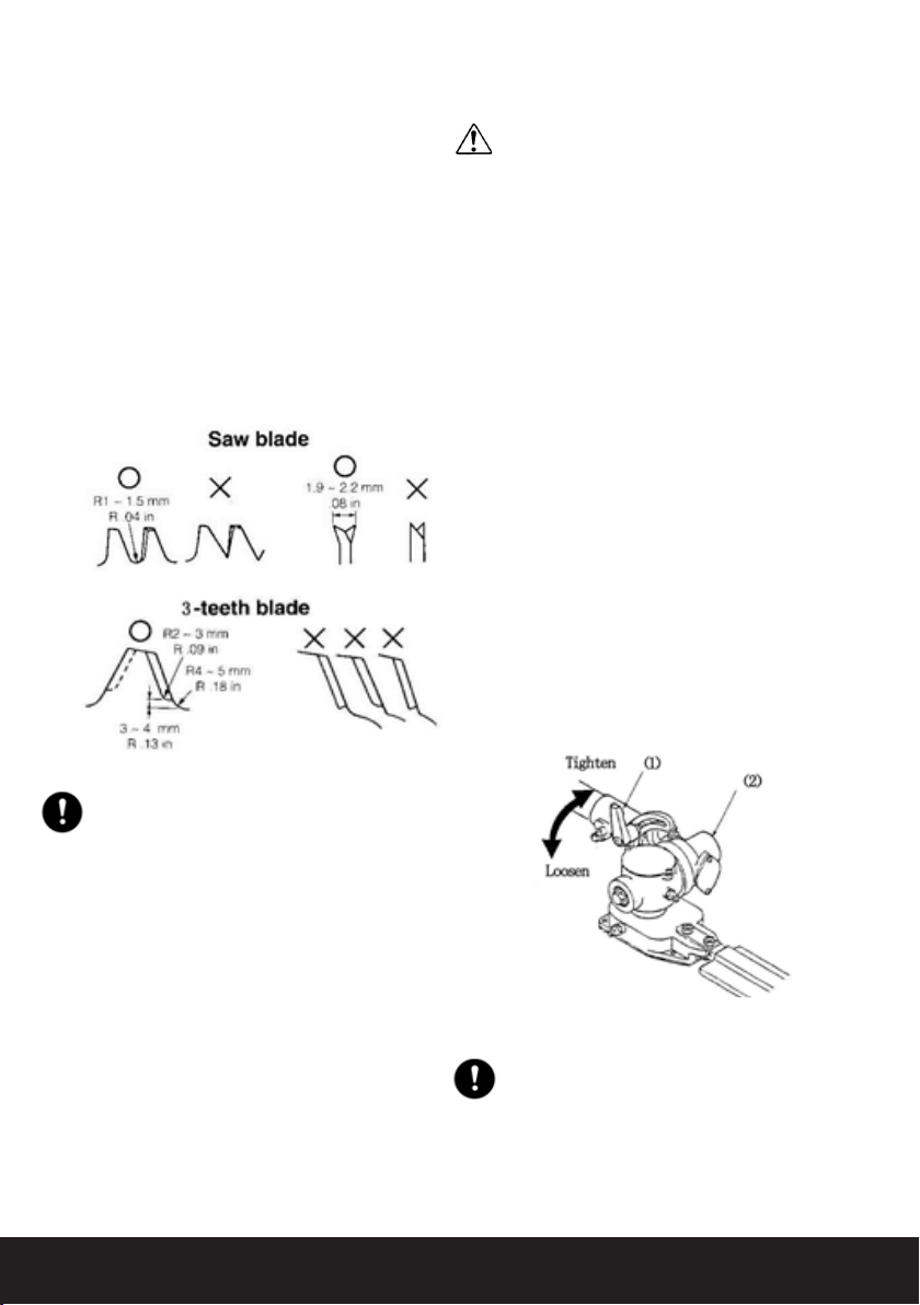
8.3.4 CHOOSE THE BLADE
• Choose a suitable recommended cutting
attachment according to the object to be cut.
• When replacing the blade always be sure to use
products, which have been certied.
WARNING
When sharpening, removing, or reattaching the
blade, be sure to wear thick, sturdy gloves and use
only proper tools and equipment to prevent injury.
8.3.5 SET UP
(1) Cover
(2) Holder
1. Detach the line head assembly completely.
2. Put on the blade, making the marked side face
the holder, put on the outer holders and fasten
the blade with the blade nut.
8.3.6 STARTING THE ENGINE
Please refer to the manual for safe operation.
WARNING
This product is equipped with a centrifugal clutch
mechanism, so the cutting attachment begins to
rotate as soon as the engine is started by putting
the throttle into the start position.
8.3.7 CUTTING METHOD
1. Use the front left side cutting.
2. Guide the blade from your right to left with it
tilted slightly to your left.
3. When mowing a wide area, start working from
your left to avoid interference of cut grass.
4. The blade could be seized by weeds if the

15
engine speed is too low, or the blade cuts too
deep into weeds. It is important to adjust the
engine speed and cutting depth accordingly to
the challenge.
WARNING
If the grass or any other object gets caught on
the blade, or if the unit starts to shake, vibrate or
the engine turns off. Thoroughly check the unit
before using it again and change the blade if it has
been damaged. Always turn off the engine before
attempting to check the blade and removing any
objects that are caught or entangled on the blade.
8.4 OPERATION
1. Check the bolt to fasten the blade and be sure
the bolt has no fault, and no abrasion.
2. Be sure that the blade and the holder have been
fastened according to instruction and that the
blade turns smoothly without abnormal noise.
3. To use the shoulder strap, hang the unit on your
right side. Adjust the strap length so the cutting
head becomes parallel to the ground
WARNING
8.4.1 CONTROLLING BLADE BOUNCE
Kick out can cause serious personal injury. Read this
section carefully to manage and understand what
causes kick outs, and how you can reduce it from
happening to remain in control of the unit if it does
occur.
8.4.2 WHAT CAUSES KICK OUT:
Kick out occurs when the moving blade makes con-
tact with an object that cannot be cut. The contact
causes the blade to stop for an instant and suddenly
move or “bounce” away from the object that was hit.
8.4.3 HOW YOU CAN REDUCE THE
CHANCE OF KICK OUT:
1. Recognize that kick out can happen by
understanding and knowing about bounce to
eliminate the element of surprise.
2. Cut brous weeds and grass only. Do not let the
blade make contact with materials it cannot cut
such as hard, woody vines and bushes or rocks,
fences, metal, etc.
3. Be prepared for bounce if you must cut where
you cannot see the blade making contact such
as in areas of dense growth.
4. Keep the blade sharp. A blunt blade increases
the chance of bounce.
5. Avoid feeding the blade too rapidly. The blade
can bounce away from material being cut if the
blade is fed faster than its cutting capability.
6. Cut only from your right to your left.
7. Keep your path in advance clear of material
that has been cut and other debris.
8.4.4 HOW YOU CAN MAINTAIN THE
BEST CONTROL:
1. Keep a good rm grip on the unit with both
hands. A rm grip can neutralize bounce and
keep your right and left hands completely
around their respective handles.
2. Keep both feet spread apart in a comfortable
stance and yet braced for the possibility that
the unit could bounce. Do not overreach. Keep
rm footing and balance.
16
8.4.5 MAINTENANCE
BLADE
• Check the blade and the fasteners for loose-
ness cracking, or bending.
• Check the cutting edges and reform with s at
le.
Point:
1. Keep the end corner sharp.
2. Round the root of the edge, using a round le.
3. Do not use water when using a grinder.
IMPORTANT
It is recommended that all ling be completed by
professionals at service dealerships as this may
result in warranty being void if the unit or trimming
attachments are damaged.
8.4.6 TRANSPORTING THE UNIT
• Turn off the engine every time when
transporting the Brush Cutter from one location
to the next paying close attention to the blade.
• Once you are nished with the unit, always
remember to place the protective cover over
the blades.
• If you are transporting the unit over long
distances, detach the blade and fasten the unit
by ropes.
8.5 OPERATION (LRT-EX ONLY)
WARNING
This product is equipped with extremely sharp
blades! If incorrectly used or handled, these blades
can be very dangerous and can cause accidents that
lead to serious injury or death.
For this reason, it is recommended that you take
an extremely cautious approach, follow all safety
procedures and instructions when using the Brush
Cutter with the Hedge Trimmer attachment.
1. Do not point the hedge trimmer blades towards
anyone.
2. Do not allow the blades to come into close
proximity with you or anyone else when
running.
3. Turn off the engine before changing the angle
of the blades or having to touch the blade.
4. Always wear work gloves made of leather or
other sturdy material when running the unit.
5. Always use the blade cover on the blade that is
provided when not in use.
6. Wear safety equipment to protect yourself from
falling trees, branches, sharp steams or ying
objects. It is advised that a face protector,
helmet, gloves and covered shoes are worn at
all times.
8.5.1 WHEN USING THE HEDGE TRIMMER
IMPORTANT
When using the hedge trimmer attachment, the
maximum cutting thickness of branches maybe
limited to approximately 3/16″ (5mm). Do not try to
cut branches thicker than this, as this may result in
damage to the trimmer.

17
ADJUSTING THE ANGLE OF THE CUTTING
BLADES
(1) Clamp lever
(2) Trimming mechanism
1. Stop the engine.
2. Turn the bolt located on the top of the trimming
mechanism counterclockwise to loosen it.
3. Adjust the angle of the blades to the desired
angle, and x the bolt rmly back into place.
8.6 OPERATION (PS-EX ONLY)
8.6.1 CHECKING OIL SUPPLY
When using the Pole Saw attachment, after starting
the engine, run the chain at medium speed and see if
chain oil splatters off in a forward direction as shown
in the gure.
The oil reservoir has the capacity to provide 40
minutes of cutting time (based on minimum ow
rate, or from a tank of fuel). Be sure to regularly rell
oil when refueling the saw and use Genuine Chain
Bar Oil.
8.6.2 ADJUSTING OIL FLOW RATE
WARNING
Do not ll the oil reservoir or adjust the
oiler when the engine is in operation or
running.
IMPORTANT
An increase in bar oil ow rate will speed up oil
consumption thus resulting in more frequent checks
on the oil reservoir. To ensure sucient lubrication, it
may be necessary to check oil levels more regularly
in comparison to fuel tank rells.
The guide bar and chain are lubricated automatically
by a pump that operates when the chain rotates. The
pump is set at the factory to deliver a minimum ow
rate, but this can be adjusted. A temporary increase
in oil ow is often desirable when cutting dense
material such as hardwood or wood with a lot of
pitch.
8.6.3 ADJUST THE PUMP AS FOLLOWS:
1. Stop the engine and make sure the stop switch
is in the OFF position.
2. Place the unit on its side with the oil reservoir
up.
IMPORTANT
The oil ow adjusting screw must be pressed in
slightly in order to turn. Failure to do so could
damage the pump and screw.
3. With a screwdriver, push-in on the oil ow rate
adjusting screw and turn-in on the desired
direction (there are three incremental settings):
(a) Clockwise-decrease lubrication
(b) Counter clockwise-increase lubrication
(c) Middle
18
WARNING
Make sure the engine has stopped and has cooled
down before performing any servicing to the unit.
Contact with moving cutting head or hot muer may
result in a personal injury.
9.1 AIR FILTER
The air lter, if clogged, will reduce engine perfor-
mance. Check and clean the lter element in warm
soapy water as required and dry completely before
installing. If the element is broken or shrunk, replace
with a new one.
9.2 FUEL FILTER
When the engine runs short of fuel supply, check the
fuel cap and the fuel lter for blockage
.
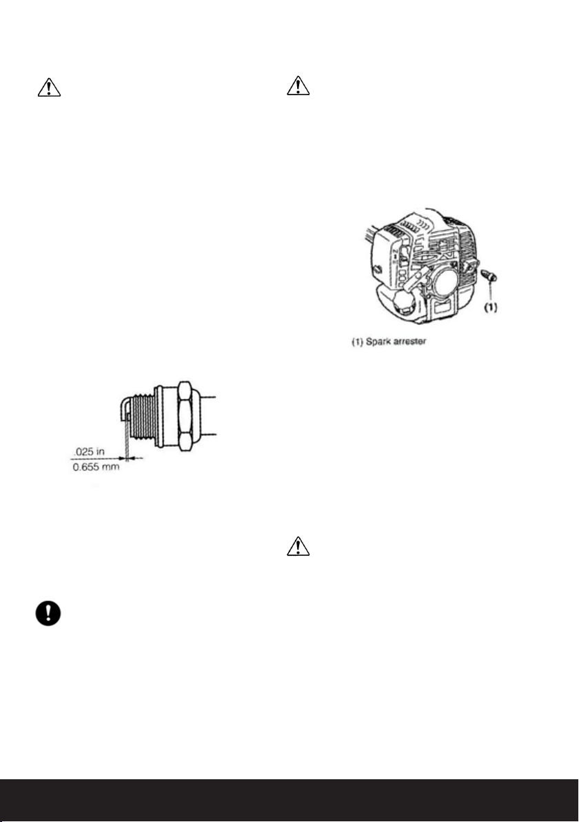
9.3 SPARK PLUG
Starting failures and misring are often caused
by fouled spark plugs. Clean the spark plug and
check that the plug gap is in the correct range. For a
replacement plug, use the correct type specied.
IMPORTANT
Using any spark plug other than those designated
may result in the engine failing to operate properly or
becoming overheated and damaged.
To install the spark plug, rst turn the plug until it is
nger tight, then tighten it a quarter turn more with a
socket wrench.
TIGHTENING TORQUE: (9.8-11.8N.m.).
9. MAINTENANCE 9.4 MUFFLER
WARNING
Periodically inspect the muer for loose fasteners,
damage or corrosion.
If any sign of exhaust leakage is found, stop using
the unit and have it repaired immediately with a
Service Dealer. Failing to do so may result in the
engine catching on re.
9.5 SPARK ARRESTER
The muer is equipped with a spark arrester to
prevent red hot carbon from ying out of the exhaust
outlet.
Periodically inspect and clean as necessary with a
wire brush.
9.6 INTAKE AIR COOLING VENT
WARNING
• Do not touch the cylinder, muer, or spark
plugs with your bare hands immediately after
using the unit when the engine is hot. The
engine can become very hot during operation,
and doing so could result in severe burns.
• Before a working session, thoroughly inspect
the unit before use. Check specic areas
around the muer and remove any wood chips
or leaves which have become attached. Failing
to do so could result in the muer overheating
and in turn could cause the engine to catch
on re.
• After every 25 hours of use, check the intake air
cooling vent and the area around the cylinder
This manual suits for next models
1
Table of contents
Other LawnMaster Brush Cutter manuals


