LawnMaster NPTBSP2609A User manual

SERVICE MANUAL
26cc 2-Cycle Brush Cutter
NPTBSP2609A
Read all safety rules and instructions carefully before servicing this tool.
601 Regent Park Court Greenville, SC 29607, 1-866-384-8432

2
Section Page
CONTENTS
CONTENTS 2
SPECIFICATIONS 3-4
GENERAL SAFETY RULES 5
PARTS AND FEATURES 6-11
WIRING DIAGRAM AND MANAGEMENT 12
GENERAL TROUBLESHOOTING 13-21
AIR & FUEL SYSTEM 22-29
THROTTLE AND STARTER SYSTEM 30-34
NOPULL™ STARTER SYSTEM 35-38
26CC 2-CYCLE ENGINE 39
GEAR HEAD AND BRUSH CUTTER BLADE 40
MANUFACTURER'S WARRANTY AND CONTACT 41

3
SPECIFICATIONS
TORQUE SPECIFICATIONS
Engine Size 2-Stroke / Full Crank
Engine Displacement Claimed / Rated 26cc / 25.4cm3
Ignition Capacitor Discharge Ignition (CDI)
Carburetor All Position Diaphragm Type With Primer Bulb
Air Filter Foam (Dry)
Engine Shut Off Auto-Reset
Throttle Control Variable Speed Trigger
Fuel / Oil Ratio 40 : 1
Fuel Tank Capacity 400 ml
Spark Plug Champion RCJ6Y
Rotor Air Gap 0.012”-0.015” (0.30-0.40 mm)
Spark Plug Gap 0.026” (0.65 mm)
Run Time on Full Tank 30 Minutes
UNIT SPECIFICATIONS
Engine
Fuel System
General
Application Description Torque Torque
(IN.LBS) (N.m)
Crankcase Apply a thermostable screw-thread glue onto the 4
screws (M5X30) and then x the crankcase cover. 53-62 6-7
Cylinder to crankcase
Apply a thermostable screw-thread glue onto the 4
screws (M5X20) and then tighten the screws securing
the cylinder to crankcase.
53-62 6-7
Spark plug to cylinder Pre-screw the spark plug to the cylinder, and then
tighten with a torque spanner. 115-137 13-15.5
Carburetor mount to
cylinder
Apply a thermostable screw-thread glue onto the 2
screws (M5X20) and tighten the screws securing the
carburetor mount to the cylinder.
35-44 4-5

4
SPECIFICATIONS
Flywheel to crankshaft
Apply a thermostable screw-thread glue onto the
crankshaft thread. Pre-screw the ange hexagon nut
(M8) and then tighten.
89-133 10-15
Clutch to ywheel
Slide the corrugated washers onto the clutch bolts
(M6X21.5). Apply a thermostable screw-thread glue
onto the bolt thread head section. Install the bolts into
the clutch and tighten the bolts securing the clutch to
ywheel.
71-89 8-10
Ignition coil to cylinder
Put the 2 screws (M5X20) through the ignition coil
and two spacers respectively. Apply a thermostable
screw-thread glue into the cylinder holes and then pre-
screw the 2 screws (M5X20). Insert a feeler gauge
of 0.014 in. (0.35mm) between the ywheel and the
ignition coil. Press down the ignition coil ush against
the feeler gauge. Tighten the screws with a torque
spanner securing the ignition coil. Remove the feeler
gauge.
27-35 3-4
Mufer to crankcase
Put the 2 bolts (M5X50) through the mufer assembly.
Apply a thermostable screw-thread glue onto the 2
bolts and secure the mufer to the crankcase using
the torque wrench.
62-71 7-8
Apply a thermostable screw-thread glue onto the
head section of 1 screw (M5X10). Pass the screw
through the positioning hole on the mufer assembly
holder and tighten the screw securing the mufer to
crankcase.
62-71 7-8
Pawl assembly to
crankshaft
Apply a thermostable screw-thread glue onto the
crankshaft thread. Pre-screw the pawl assembly to
crankshaft, and then tighten using the torque wrench.
62-80 7-9
Air lter base to
carburetor
Pre-screw the nuts (M5) with washers, and then
tighten using the pneumatic tool. 27-35 3-4
Fuel tank bracket to
crankcase
Apply a thermostable screw-thread glue onto the
screw (M5X10) and pass it through the hole on fuel
tank bracket. Tighten the screw securing the fuel tank
bracket to crankcase.
27-35 3-4
Fuel tank to crankcase
Apply a thermostable screw-thread glue onto the
screw (M5X12). Pass it through the fuel tank hole.
Tighten the screw securing the fuel tank to crankcase.
27-35 3-4
Cylinder pressure plate
Apply a thermostable screw-thread glue onto the
screw (M5X10). Pass the screw through the cylinder
pressure plate hole and then tighten it onto the
cylinder.
27-35 3-4
Electric starter
assembly to crankcase
Align the 2 screw holes on the electric starter
assembly with the screw holes on crankcase. Tighten
the 2 screws (M5X60) securing the electric starter
assembly to crankcase.
27-35 3-4
Rear engine cover
assembly
Tighten the 2 screws (ST3.9X30F) to secure the rear
engine cover. 12-13 1.3-1.5

5
SPECIFICATIONS
Flywheel cover to
crankcase
Apply a thermostable screw-thread glue into the two
holes on crankcase. Tighten the 2 screws (M5X15)
securing the ywheel cover to crankcase.
53-64 6-7.2
Lower engine cover
assembly
Place the lower engine cover onto crankcase. Tighten
the 3 screws (1*ST3.9X8, 2*M5X10) securing the
lower engine cover.
10-12
1.1-1.3 (for
1*ST3.9X8)
27-35
3-4 (for
2*M5X10)
Upper engine cover
assembly
Tighten the 3 screws (M5X35) securing the upper
engine cover. 27-35 3-4
Spark plug cover to
upper engine cover
Tighten the screw (M5X10) securing the spark plug
cover to upper engine cover. 27-35 3-4
Lower engine cover to
upper engine cover
Tighten the screw (ST3.9X12) to secure the upper and
lower engine covers (on mufer side). 10-12 1.1-1.3
Right handle cover to
left handle cover
Tighten the screws (ST3.9X16) to secure the right and
left parts of the main handle. 10-12 1.1-1.3
Transmission yoke to
ywheel cover
Apply a thermostable screw-thread glue into the four
screw holes on ywheel cover. Tighten the screws
(M5X20) securing the transmission yoke.
53-62 6-7
Shaft connection sleeve
to upper shaft
Align the shaft connection sleeve with the screw holes
on upper shaft. Tighten the screws (M5X25 & M5X12)
securing the shaft connection sleeve to upper shaft.
53-62 6-7
Gear box to lower shaft
Align the screw holes on the gear box with the lower
shaft. Tighten the screws (M5X12, M6X25, M6X10)
securing the gear box to lower shaft.
53-62 6-7
Transmission yoke
assembly
Align the screw holes on the transmission yoke with
the screw holes on upper shaft. Tighten the screws
(M5X12 & M6X25) securing the transmission yoke to
upper shaft.
53-62 6-7
Shoulder strap clasp
assembly
Adjust the position of the shoulder strap clasp and
tighten the screw (M5X16). 27-35 3-4
Trimming line cutting
blade assembly
Tighten the screws (ST3.9X16) with washers to secure
the trimming line cutting blade to the debris guard. 10-12 1.1-1.3
Ratchet to electric
starter assembly
Attach the ratchet to the electric starter lower cover.
Apply a thermostable screw-thread glue onto the head
section of the screw (M5X10) and tighten the screw
(M5X10) securing the ratchet.
27-35 3-4
Electric starter motor
assembly
Align the electric starter motor with the screw holes on
the electric starter upper cover. Apply a thermostable
screw-thread glue onto the head section of the screws
(M3X8) and tighten the screw securing the electric
motor.
4-6 0.5-0.7
Electric starter lower
and upper covers
assembly
Tighten the two screws (ST2.9X12F) securing the
lower and upper covers of the electric starter. 4-5 0.4-0.6

6
GENERAL SAFETY RULES
SAFETY
To protect the eyes from loose objects that could be thrown from the brush cutter, always wear eye
protection with side shields marked to comply with ANSI Z87.1 when operating the brush cutter.
Use only genuine manufacturer’s replacement parts for this product. Failure to do so may cause poor
t, poor function and possible injury.
Scarfs, neckties, jewelry, jackets or other loose clothing and accessories should be avoided as they
can be caught on or become entangled in the brush cutter. Secure hair so it is above shoulder level. To
protect your legs and feet, long pants and closed toed shoes should be worn.
To improve your grip and protect your hands, wear heavy-duty nonslip gloves.
The sound level exceeds 85 dB(A). To prevent hearing damage, always wear sound barriers (ear plugs
or ear mufers).
GENERAL BRUSH CUTTER SAFETY
Never operate the brush cutter with a damaged guard or without the guard in place.
Avoid getting into direct contact with the brush cutter blade.
Always remember to keep both hands on the control handles when the engine is running.
Do not operate the brush cutter if there is a fuel leak as it is a re hazard. The fuel leak must be xed
prior to operating the brush cutter.
Empty the fuel tank before storing if the brush cutter will not be used for a few days.
Make sure the control handles have not accumulated oil and fuel and are clean and dry.
Beware of blade kickback:
- Blade kickback may occur when the spinning blade contacts an object that it does not immediately
cut.
- Blade kickback can be violent enough to cause the unit and/or operator to be propelled in any
direction, and possibly lose control of the unit.
- Blade kickback can occur without warning if the blade snags, stalls or binds.
- Blade kickback is more likely to occur in areas where it is difcult to see the brush or vegetation being
cut.
A coasting blade can cause injury while it continues to spin after the engine is stopped or throttle
trigger is released. Maintain proper control until the blade has completely stopped rotating.
See Operator’s Manual for additional safety precautions.
WORK AREA
Operate only in well ventilated areas.
Observe all safety regulations for the safe handling of fuel. Mix and handle fuel in a container approved
for storing gasoline. Wipe the brush cutter dry if fuel is spilled on it. Always move away from the fueling
area before starting the engine.
Fuel the brush cutter at least 10 ft. (3 m) from the place where you start the engine and operate the
brush cutter.
NOTE: The brush cutter blade will rotate during carburetor adjustment. Wear protective equipment and
observe all safety instructions.
7
PARTS AND FEATURES
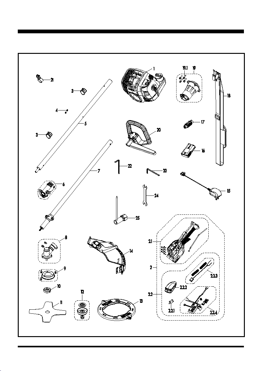
NPTBSP2609A EXPLODED VIEW

8
PARTS AND FEATURES
NPTBSP2609A PARTS LIST
Key
Number Application Description Quantity
1 641002101 Cleva 26cc 2-Cycle Engine 1
2 321001102 Throttle-body & Start Set 1
2.1 321001103 Throttle-body Set 1
2.2 321001104 Starter Set 1
2.2.1 321001105 Micro Switch 1
2.2.2 321001106 Starter Switch Assembly 1
2.2.3 321001107 Stop Switch Set 1
2.2.4 321001108 PCB Assembly 1
3 321001109 Handle Spacer 2
5 641001104 Aluminum Upper Shaft 1
4 141004102 Cable Clamp 2
6 641001105 Shaft Connection Sleeve 1
7 641001106 Aluminum Lower Shaft 1
8 641001107 Gear Box 1
9 641001108 Blade Guard Assembly 1
10 221003105 Cover Plate 1
11 RBB2609A 9" Blade 1
12 641001111 Blade Clamp Assembly 1
13 641001112 Saw Blade Sheath 2
14 641001113 Debris Guard 1
15 321001127 Charger 1
16 321001114 7.2V Lithium-Ion Battery 1
17 321001113 Wire Lock 1
18 221003102 Shoulder Strap 1
19 641001115 Clutch Assembly 1
19.1 321005103 Screw 4
20 641001116 P-Handle 1
21 321001128 Shoulder Strap Clasp 1
22 321004122 M5 Hexagon Socket Wrench 1
23 321004121 M6 Hexagon Socket Wrench 1
24 321004123 Open End Wrench 1
25 321004124 Socket Wrench 1

9
PARTS AND FEATURES
EXPLODED VIEW 26CC 2-CYCLE ENGINE

10
PARTS AND FEATURES
NPTBSP2609A PARTS LIST
Key
Number Application Description Quantity
1 321001130 Spark Plug Cover 1
2 321001131 Nut 1
3 321001132 Upper Engine Cover 1
4 321001133 Logo 1
5 321001134 Air Deector 1
6 321002109 Cylinder Air Damper 1
7 321001136 Mufer Cover 1
8 321001137 Mufer 1
9 321001138 Insulation Sheet 1
10 321001139 Spark Plug 1
11 321002110 Gasket 1
12 641002103 Ignition Coil Assembly 1
13 321002112 Positive Stop Switch Cable 1
14 321002113 Spacer Set 4
15 321002114 Cylinder 1
16 321002115 Gasket 1
17 321001143 Pawl Assembly 1
18 321002116 Electric Starter Assembly 1
19 321002117 Rear Engine Cover 1
20 321002118 Carburetor Mount Assembly 1
21 321002119 Washer 1
22 321002120 Carburetor 1
23 321001147 Air Filter Base 1
24 321001148 Air Filter 1
25 321001149 Air Filter Cover 1
26 321001150 Rotary Knob 1
27 321001151 Choke Lever 1
28 321001152 Fuel Cap Assembly 1
29 321002121 Fuel Tank Grommet 1
30 321002122 Fuel Tank 1
31 321002123 Fuel Tube 1
32 321002124 Fuel Tube 1
33 321002125 Fuel Line Filter 1
34 321001154 Rubber Pad 1
35 321001155 Fuel Tank Bracket 1
36 321002126 Negative Stop Switch Cable 1
37 321001156 Lower Engine Cover 1

11
38 321002127 Crankshaft Set 1
39 321002128 Piston Ring 2
40 321002129 Piston 1
41 321002130 Retainer Ring 2
42 321002131 Retainer Ring 2
43 321002132 Needle bearing 1
44 321002133 Piston Pin 1
45 321002134 Crankcase Assembly 1
46 641001126 Flywheel 1
47 321002143 Flange Nut M8 1
48 311014125 Flat Key 1
49 321002145 Clutch Assembly 1
50 321002146 Washer 2
51 321002147 Corrugated Washer 2
52 321002148 Bolt 2
53 321002149 Flywheel Cover 1
54 321002150 Round Ring 2
55 321002151 Screw 2
56 321002152 Screw 3
57 321002153 Self-Tapping Screw 2
58 321002154 Screw 2
59 321002155 Lower Rear Engine Cover Plate 1
60 321002156 Heat Resistant Grommet 1
61 321001160 Screw 6
62 321001161 Self-Tapping Screw 2
63 321002157 Screw 2
64 321002158 Screw 4
65 321002159 Screw 6
66 321001163 Screw 2
67 321001164 Rubber Plug 1
68 321001165 Nut 2
69 321001166 Washer 5
70 321001162 Self-Tapping Screw 1
71 321001210 Screw 1
72 321005103 Screw 2
PARTS AND FEATURES

12
WIRING DIAGRAM AND MANAGEMENT
- IGNITION AND STARTING
2S Battery Pack Starter Switch (Self-reset)
Stop Switch (Self-reset)
3.5 Bullet Terminal
Ignition Coil
Spark Plug
Engine
Engine Body Engine Body
3.5 Bullet Terminal
NTC
NTC
RD
RD
BK
BK BK
BK BK
BK
RD
Bullet Terminal(BL)
Bullet Terminal(BL)
Electric
Motor
EngineHandle
lgnition
Handle
M
RD
J10 J9
J8
GND M+
M-
Battery
Connector
LED
Panel
Battery Connector
PCB ASSEMBLY
VCC’
Push-Start
Ignition

13
GENERAL TROUBLESHOOTING
PROBLEM POSSIBLE CAUSE SOLUTION
The electric motor does
not start, and the battery
indicator LED ashes red.
The battery is not fully
charged or not inserted
correctly.
Charge the battery fully and insert it
correctly.
The motor does not start,
and the battery indicator
LED ashes yellow.
The battery is overheated.
Allow the battery to cool to room
temperature. Re-start the tool after about
30 minutes.
The motor does not start,
and the battery indicator
LED ashes green.
Possible short circuit in the
electric motor or the motor
drive lines.
Check if there is a short circuit in the
electric motor or the motor drive lines
referring to page 36.
The motor does not start,
and the battery indicator
LED ashes alternatively
red and green.
The starting current is
excessive - the engine or
electric motor may be seized
or cannot rotate smoothly.
Check if the engine or the electric motor is
stuck and cannot rotate smoothly referring
to page 36.
The motor does not start,
and the battery indicator
LED is continuously on.
There is an open circuit from
the PCB output to the motor
connecting line.
Check if there is an open circuit occurs
from the PCB output to the motor
connecting line referring to page 36.
The motor starts, but the
engine does not start.
The starter drive system is
broken.
Remove the electric starter. Replace the
drive system.
If drive system of the starter is in good
condition, the engine may be broken.
The engine does not start.
No spark or weak spark.
Clean or replace the spark plug. Reset the
spark plug gap 0.026”±0.002” (0.65±0.05
mm).
Check the gap between ignition coil and
ywheel. Make sure the gap is 0.012’’-
0.015’’ (0.30-0.40mm).
The air lter is blocked. Clean the air lter.
The fuel tank valve is
blocked. Remove the blockage or replace.
Incorrect lubricant/fuel. Use correct lubricant/fuel.
The fuel tube is blocked or
broken. Clean or replace.
Incorrect carburetor
adjustment. Re-adjust the carburetor.
The carburetor is blocked. Remove the blockage.
Excessive oil in carburetor. Tighten the carburetor nut or replace the
carburetor washer.

14
GENERAL TROUBLESHOOTING
The engine stops during
operation.
No fuel. Add fuel to the fuel tank.
The fuel tube is blocked. Remove the blockage.
The carburetor nut loosens
and has air leakage.
Tighten the carburetor nut or replace the
carburetor washer.
No spark or weak spark.
Clean or replace the spark plug. Reset the
spark plug gap.
Check the gap between ignition coil and
ywheel. Make sure the gap is 0.012’’-
0.015’’ (0.30-0.40mm).
Abnormal engine
compression.
Check if the piston ring sinters and the
piston and piston ring wear status. Check
the carbon deposit status in combustor.
Check the wear status inside cylinder.
Check if the spark plug loosens. Check
the gap between ignition coil and ywheel.
Make sure the gap is 0.012’’-0.015’’ (0.30-
0.40mm).
The engine is ooded.
Remove the spark plug. Clip the fuel tube
for fuel entering. Press the start button to
remove the fuel inside the cylinder.
The engine has less power.
The choke lever is closed. Open the choke lever.
The air lter is blocked. Clean the air lter.
The fuel lter is blocked. Remove the blockage or replace.
Incorrect lubricant/fuel. Use correct lubricant/fuel.
Incorrect carburetor
adjustment. Re-adjust the carburetor.
Carburetor washer hardens. Replace.
The main nozzle of the
carburetor is blocked.
Clean or replace the carburetor if
necessary.
The spark plug is worn out. Replace with new spark plug.
The carburetor has air
leakage. Tighten the carburetor.
The fuel has been
contaminated with water. Empty tank and replace with clean fuel.
Mufer has carbon deposit. Remove the carbon deposit.
Exhaust port has carbon
deposit. Remove the carbon deposit.
Piston ring sinters. Clean the ring groove or replace the piston
ring.
Cylinder worn. Replace the cylinder.
Piston and piston ring are
worn out. Replace.

15
GENERAL TROUBLESHOOTING
No spark.
Electrode of the spark plug
is wet. Dry the spark plug.
Spark plug has carbon
deposit. Remove the carbon deposit.
Spark plug insulation is
broken. Replace the spark plug.
Spark plug gap is too big/
small. Adjust to 0.026”±0.002” (0.65±0.05 mm).
Electrode of the spark plug
is burnt out. Replace the spark plug.
High voltage line of the
ignition coil is broken. Replace the high voltage line.
Stator of the ignition coil is
broken or burnt out. Replace the stator.
Poor contact of the high
voltage line and the jump
ring.
Amend.
Spark plug cap is broken. Replace.
Engine will not start but
spark plug res.
Excess fuel inside spark
plug.
Remove the spark plug. Clip the fuel tube
for fuel entering. Press the start button to
remove the fuel inside the cylinder.
Fuel is not clean, with water. Replace the fuel.
Cylinder and piston ring
wear. Replace.
The spark plug loosens. Tighten.
Crankcase has air leakage. Replace the gasket.
Cylinder has air leakage. Replace the gasket.
No fuel. Add fuel.
No fuel in primer bulb. Prime the bulb.
Engine is not choked. Engage the choke.
Fuel tank valve is blocked. Remove the blockage.
The engine cannot be
stopped.
The switch wire does not
connect. Connect the wire.
The switch is broken. Replace.
The clutch engages during
idle speed.
Clutch is damaged. Replace.
The free length of the clutch
spring is too long. Replace.
Clutch is off center. Replace.

16
GENERAL TROUBLESHOOTING
No load speed is not
stable/consistent.
Incorrect carburetor
adjustment. Re-adjust the carburetor.
The carburetor has an air
leakage. Replace or re-tighten.
Fuel tube is broken. Replace.
Crankcase washer has air
leakage. Replace.
Fuel seal has air leakage. Replace.
After release the throttle
lever, the brush cutter
blade remains rotating.
Idle speed is too high. Adjust the engine.
Clutch spring is broken. Replace.
Clutch friction plate is
broken. Replace.
The engine accelerates,
but the brush cutter blade
does not rotate.
Spline of the axle of
rotation or the spline of the
transmission yoke is worn
out.
Replace.
Irregular vibration.
Brush cutter blade is not
installed tightly. Secure the brush cutter blade into place.
Brush cutter blade is bent. Repair or replace.
Brush cutter blade is worn
out. Replace.
The drive shaft is bent. Replace.
Worn bearings. Replace.
Clutch is off center. Replace.
17
GENERAL TROUBLESHOOTING
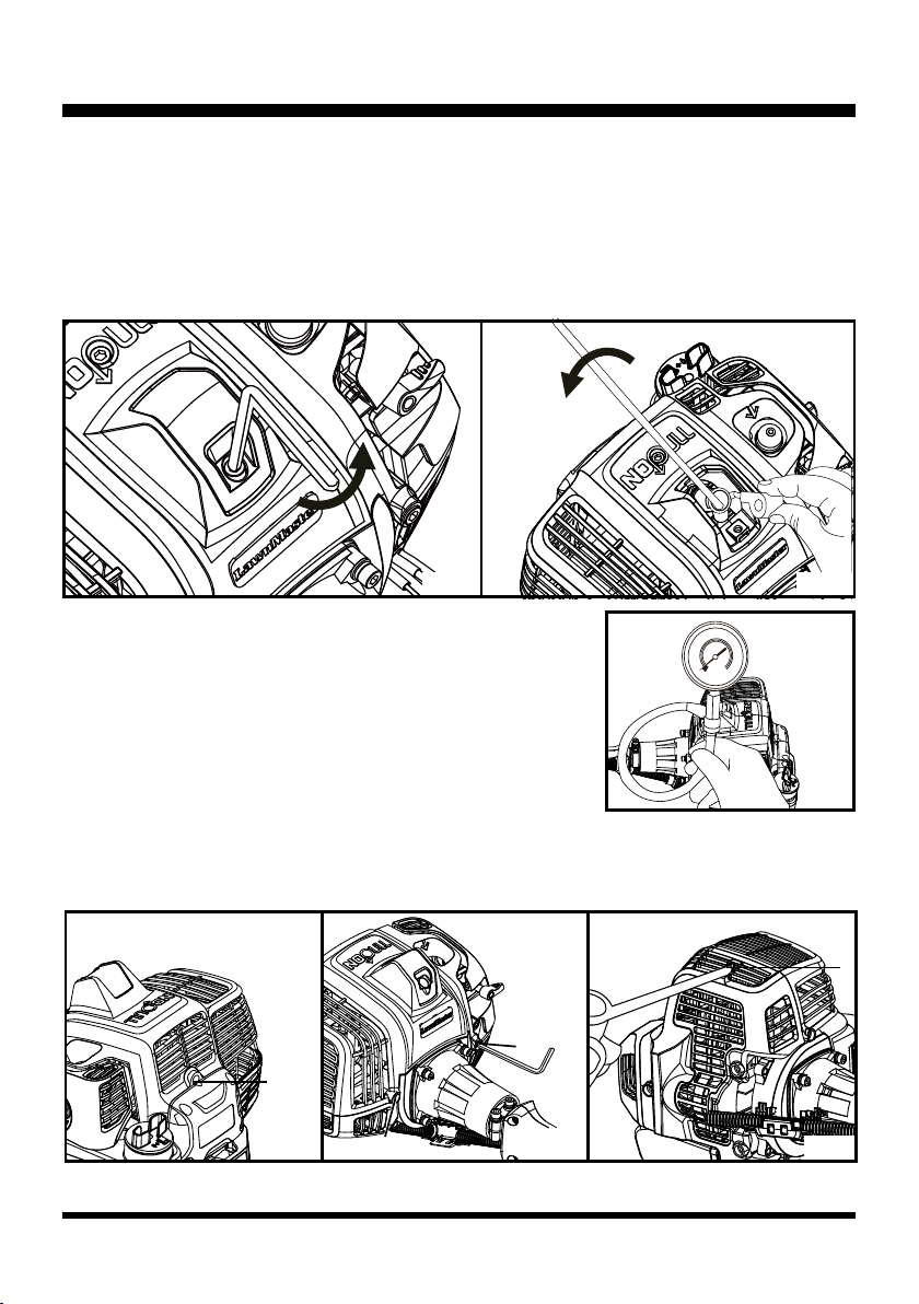
■ Rotate a compression gauge into the spark plug hole (Fig. 3).
Place the choke lever in the RUN position. Engage the throttle
safety and throttle trigger together to open the throttle and the
choke lever in the on position. Lift the start button cover and
press the start button 3-5 times until the gauge needle reaches its
peak (stops moving). Engine compression should be >0.6MPa.
Ignition System (See Figs. 4-9)
■ Remove the upper engine cover by removing the 4 screws with the provided hex wrench and
screwdriver (Fig. 4 - 6)
1
4
2
3
Fig. 5Fig. 4
Fig. 2Fig. 1
Engine Compression (See Figs. 1-3)
Low compression will cause erratic idling, low power, and hard starting when hot. To test the engine
compression:
■ Remove the spark plug cover using the provided hex wrench (Fig. 1).
■ Remove the spark plug cap. Fully cover the spark plug using the provided socket wrench. Rotate
the wrench counter-clockwise to remove the spark plug (Fig. 2).
Fig. 6
0
30
60
90
120 150 180
210
240
270
300
Fig. 3
18
GENERAL TROUBLESHOOTING
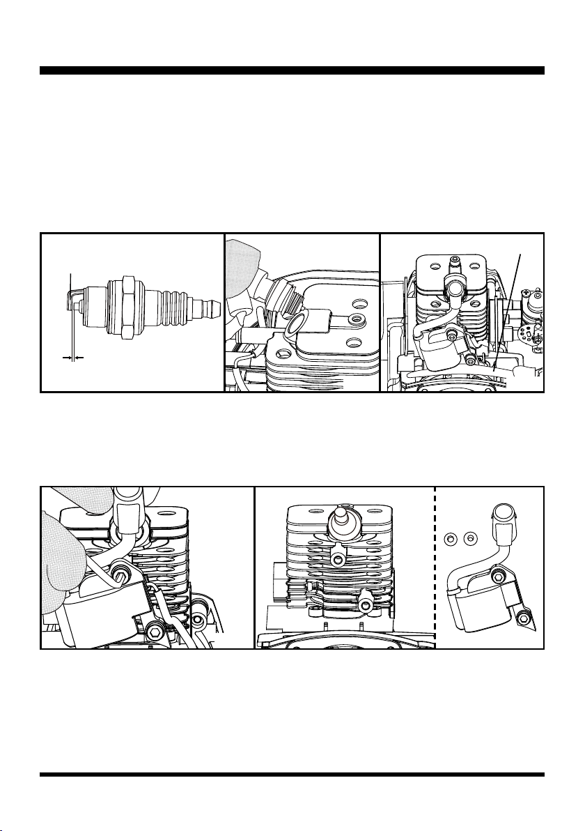
Feeler Gauge
■ Remove the spark plug cover. Remove the spark plug cap and the spark plug. Check and remove
the carbon deposit in the spark plug. The spark plug gap should be 0.65±0.05mm. Inspect the
electrodes for wear and deposits (Fig. 7).
■ Install the spark plug into the spark plug cap. Contact the negative electrode to the aluminum part
(Fig. 8).
■ Press the start button to check if the spark plug sparks.
■ Check the gap between the rotor and the ignition coil. Make sure the gap is between 0.012 and 0.015
in. (0.30-0.40 mm) as instructed in step 3 of the Ignition Coil Replacement section (Fig. 9).
Fig. 8Fig. 7
Ignition Coil Replacement (See Figs. 10-11)
■ Remove the upper engine cover.
■ Remove the spark plug cover and the spark plug cap. Remove the 2 screws. Remove the ignition
coil and the washers (Fig. 10 - 11).
Fig. 11Fig. 10
■ Replace with a new ignition coil.
■ To adjust the gap between the rotor and the ignition coil, rst insert a feeler gauge of 0.014 in.
(0.35mm) between the rotor and the ignition coil, then rotate the rotor and align the magnetic pole
of the rotor with the ignition coil. Press down the ignition coil ush against the feeler gauge. Tighten
the screws to x the ignition coil. Rotate the rotor counter-clockwise to remove the feeler gauge. Re-
check to ensure the gap is 0.012-0.015 in. (0.30-0.40 mm) (Fig. 9).
Outer Electrode
0.026 in. (0.65 mm)
Fig. 9
19
GENERAL TROUBLESHOOTING
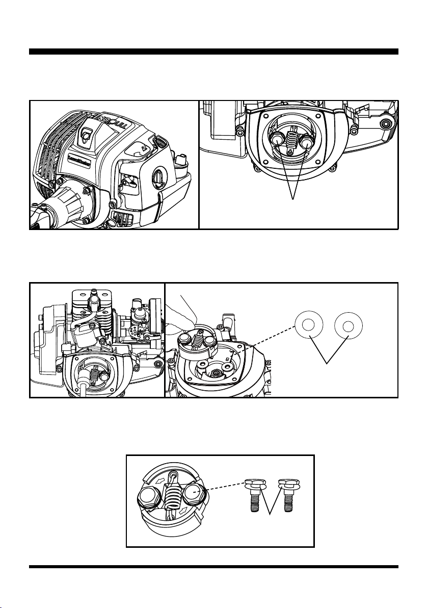
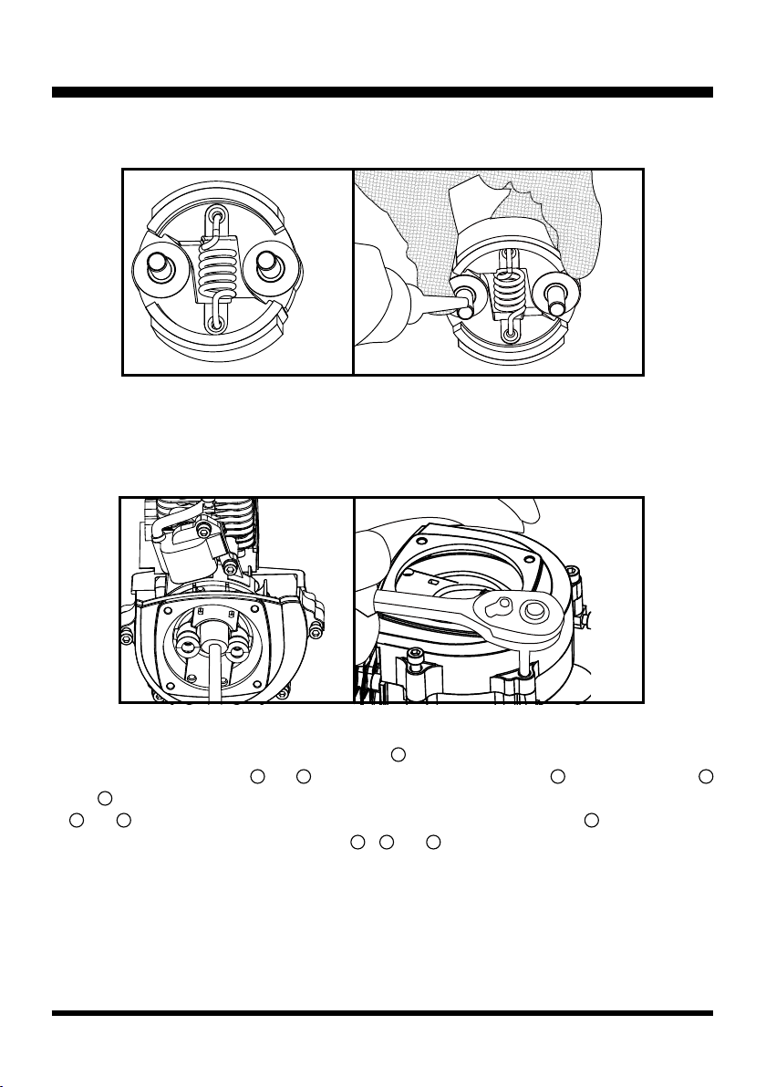
Clutch Replacement (See Figs. 12-18)
■ Remove the 4 screws to remove the transmission yoke (Fig. 12 & 13).
■ Remove the upper engine cover.
■ Unscrew the bolts on the clutch assembly using an impact driver or wrench (Fig. 14).
■ Remove the 2 bolts and corrugated washers. Then remove the clutch and at washers (Fig. 15).
■ Replace with a new clutch.
■ Slide the corrugated washers onto the bolts. Then install the bolts together with the corrugated
washers into the clutch, with the side of the clutch marked with the direction of rotation facing
upwards (Fig. 16).
Fig. 13
Fig. 15
Fig. 12
Fig. 14
Fig. 16
Bolts
Flat Washers
Corrugated Washers
20
GENERAL TROUBLESHOOTING
Flywheel (Rotor) Replacement (See Figs. 19-22)
■ Remove the clutch.
■ Remove the nut using an impact driver (Fig. 19).
■ Remove the 2 screws to remove the ywheel cover (Fig. 20).
■ The ywheel can be removed by a puller (Fig. 21). Choose an appropriate puller to remove the
ywheel. Before using the puller, rotate screw rod
1
counter-clockwise till it is 1/4 to 1/2 its length
through. Ensure screw rods
2
and
3
are protruded longer than screw rod
1
. Rotate screw rods
2
and
3
clockwise into the corresponding threaded holes as shown in Fig. 21. Make sure screw rods
2
and
3
are level and in same length. Then use a spanner to rotate screw rod
1
clockwise until
the ywheel is removed. Rotate screw rods
1
,
2
and
3
counter-clockwise to remove the puller
from the ywheel.
■ Turn the clutch upside down and slide the at washers onto the bolts. Apply the thread-locking glue
for 3-5 screw threads and then re-install the clutch (Fig. 17 & 18).
Fig. 18Fig. 17
Fig. 19 Fig. 20
Other manuals for NPTBSP2609A
2
Table of contents
Other LawnMaster Brush Cutter manuals


