LAWO mc296 User manual


Copyright
All rights reserved. Permission to reprint or electronically reproduce any document or graphic in whole
or in part for any reason is expressly prohibited, unless prior written consent is obtained fromthe Lawo
AG.
All trademarks and registered trademarks belong to their respective owners. It cannot be guaranteed that
all product names, products, trademarks, requisitions, regulations, guidelines, specifications and norms
are free from trade mark rights of third parties.
All entries in this document have been thoroughly checked; however no guarantee for correctness can
be given. Lawo AG cannot be held responsible for any misleading or incorrect information provided
throughout this manual.
Lawo AG reserves the right to change specifications at any time without notice.
© Lawo AG, 2021

3/65
Table of Contents
mc²96 Installation & Service Guide Version: 1.0/3
Table of Contents
1. Introduction ......................................................................................................................................... 5
2. Important Safety Instructions ................................................................................................................ 6
3. The Hardware ..................................................................................................................................... 7
Overview.................................................................................................................................... 73.1
Frame Variants .......................................................................................................................... 73.2
Mounting Options ....................................................................................................................... 83.3
Channel Controls ........................................................................................................................ 93.4
Centre Section Controls ............................................................................................................ 113.5
Central User Panel Options ....................................................................................................... 133.6
Overbridge Metering ................................................................................................................. 143.7
Console Rear Panel .................................................................................................................. 153.8
Ethernet Server Types .............................................................................................................. 163.9
Control Surface Wiring ............................................................................................................. 163.10
4. Installation ......................................................................................................................................... 20
Unpacking ............................................................................................................................... 204.1
Packing List ............................................................................................................................. 204.2
Mounting the Frame .................................................................................................................. 214.3
Dimensions and Weight ............................................................................................................ 214.4
Temperature and Cooling .......................................................................................................... 214.5
MinimumDistances for Control Surface Mounting ....................................................................... 224.6
Installing the Console Keyboard ................................................................................................. 234.7
Fitting the Script Tray ............................................................................................................... 244.8
Wiring from the Control Surface ................................................................................................ 254.9
Power ...................................................................................................................................... 264.10
Grounding ................................................................................................................................ 274.11
Control .................................................................................................................................... 284.12
Installing Extender Frames ........................................................................................................ 294.13
Local IO................................................................................................................................... 304.14
SFP Modules ........................................................................................................................... 334.15
Front Buffer Connections .......................................................................................................... 344.16
Connecting a Talkback Mic ....................................................................................................... 354.17
5. Service Procedures ........................................................................................................................... 36

mc²96 Installation & Service Guide
Table of Contents
4/65 Version: 1.0/3
Preparation .............................................................................................................................. 365.1
Restarting a Bayserver or Gateserver ......................................................................................... 375.2
Replacing a Panel .................................................................................................................... 385.3
Using the Hood Fastener ........................................................................................................... 425.4
Replacing a Fader .................................................................................................................... 435.5
Replacing a User Panel ............................................................................................................. 455.6
Replacing a TFT Display ........................................................................................................... 495.7
Calibrating a Touch-screen ....................................................................................................... 495.8
Bayserver & Gateserver Switch Settings ..................................................................................... 505.9
Replacing a Console Power Supply ............................................................................................ 525.10
Replacing the Local IO .............................................................................................................. 545.11
Replacing the Network Switch .................................................................................................... 565.12
Replacing the Monitoring Computer ............................................................................................ 585.13
6. Appendices ....................................................................................................................................... 60
Part Numbers ........................................................................................................................... 606.1
Wiring Diagrams ...................................................................................................................... 616.2
Connector Pin-Outs & IOSpecifications ..................................................................................... 626.3
SMPTE ST2022-7 (SPS) ........................................................................................................... 656.4

mc²96 Installation & Service Guide Version: 1.0/3 5/65
1. Introduction
1. Introduction
About this Manual
This document describes the hardware, installation and service procedures for the mc²96 control surface.
Look out for the following which indicate:
Notes - points of clarification.
Tips - useful tips and short cuts.
Attention - alert you when an action should always be observed.
Further Information
Mechanical drawings and data sheets (including weights and dimensions) are available from the Downloads
area at www.lawo.com (after Login)..
We also recommend that you carefully observe the release notes delivered with your system.
Lawo User Registration
For access to the Downloads area and to receive regular product updates, please register at:
www.lawo.com/registration.

mc²96 Installation & Service GuideVersion: 1.0/36/65
2. Important Safety Instructions
2. Important Safety Instructions
Please observe all of the instructions provided in the "General Safety Information for Lawo Equipment" booklet
delivered with your devices. Double-click here to open the same information (as a pdf).
Please also observe the "Safety Information" included in the product data sheets. These are available from the
Downloads area at www.lawo.com (after Login).
mc²96 Installation & Service Guide Version: 1.0/3 7/65
3. The Hardware
3. The Hardware
This chapter describes the control surface hardware and options.
3.1 Overview
The mc296 comes in a range of flexible frame sizes and layouts. The control surface includes integrated local IO
and dual redundant power supplies. The frame is convection cooled and so there are no fans, except in the RTW
TM9.
3.2 Frame Variants
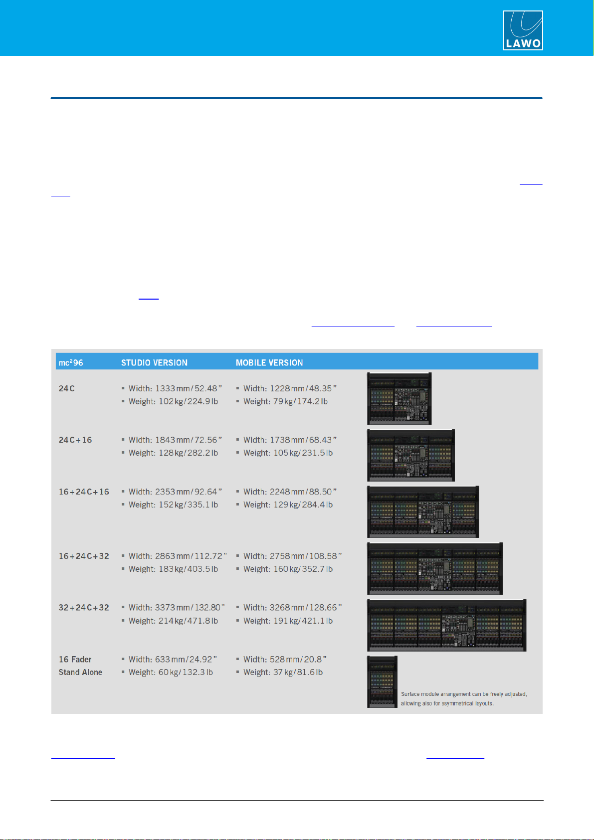
The control surface can scale from 24 up to 120 faders. The five standard frame layouts are shown below.
The central bay (24C) houses the centre section with 8 main faders plus one 16-fader channel bay. Additional
channel bays may then be added as required. Each 16-fader channel bay adds 510mm to the width of the
console. The position of the central bay is flexible allowing for asymmetrical layouts which differ to those pictured
below. Double-click here to view all possible frame variants (as a pdf).
A frame can be expanded by adding 16-fader stand-alone extenders up to the maximum of 120 faders. The
number of faders in a frame can be increased by fitting the Fader Panel Upper and Xtra Main Faders options.
mc296 Standard Frame Layouts
The weights shown above for the "Studio Version" are for a console with no stand.
Mechanical drawings and data sheets for all frame variants are available from the Downloads area at
www.lawo.com (after Login). To help locate the correct data sheet, please refer to the part numbers appendix.
mc²96 Installation & Service GuideVersion: 1.0/38/65
3. The Hardware
To aid transportation, frames with up to three additional channel bays (72-fader) can be delivered either as a
single monolithic frame (978/50-xy) or as a spit frame (978/51-xy). Frames with four or more additional channel
bays (88-faders upwards) are always delivered as split frames (978/51-xy). Following transportation, split-frames
must be combined to form a single unit.
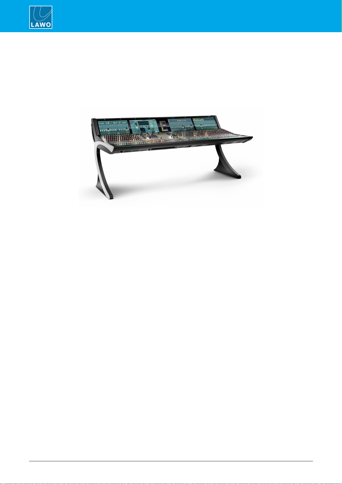
3.3 Mounting Options
mc296 Studio Version (with stand)
Each frame can be ordered for either Studio or OB-Van (Mobile) mounting.
The Studio version comes with wider side panels and a console stand (for a free-standing frame). The stand
comprises two detachable legs which are supplied with wooden mounting plates to attach the legs to the frame.
The OB-Van version is fitted with narrow aluminum side plates and is designed for crossbar mounting (i.e. no
feet or legs are supplied).

mc²96 Installation & Service Guide Version: 1.0/3 9/65
3. The Hardware
3.4 Channel Controls
Channel bays can be specified with either single or dual faders.
3.4.1 Single-Fader Bays
As standard, each channel bay is fitted with the following control panels.
1 x Channel Display (978/13)
A high resolution, touch-screen TFTdisplay.
1 x FC Panel (978/11)
with 112 rotary encoders, 24 mini TFTdisplays, 148 push-buttons.
1 x Fader Panel (978/10)
with 16 x100mm motorised faders, 8 mini TFT displays, 160 push-
buttons.

mc²96 Installation & Service GuideVersion: 1.0/310/65
3. The Hardware
3.4.2 Dual-Fader Bays
Optionally, the FC Panel (978/11) can be replaced by the Fader Panel Upper (978/12) to provide a second row
of short-scale fader strips at the expense of Free Controls 3 to 6. The 978/12 can be fitted to individual bays as
required, allowing you to combine single and dual-fader bays within the same surface.
1 x Channel Display (978/13)
Identical to a standard channel bay.
1 x Fader Panel Upper (978/12)
with 16 x60mm motorised faders, 48 rotary encoders, 16 mini TFT
displays, 214 push-buttons.
Replaces the 978/11.
1 x Fader Panel (978/10)
Identical to a standard channel bay.
3.4.3 Ethernet Bayserver
Internally, each channel bay is fitted with an Ethernet Bayserver mounted behind the display. This handles the
control data within the bay, and connects to the internal network.
3.4.4 Further Information
All faders and rotary encoders are touch-sensitive.
You can find more information about the individual panels and displays in their data sheets.
mc²96 Installation & Service Guide Version: 1.0/3 11/65
3. The Hardware
3.5 Centre Section Controls
The centre section can be specified with either 8 or 16 main faders.
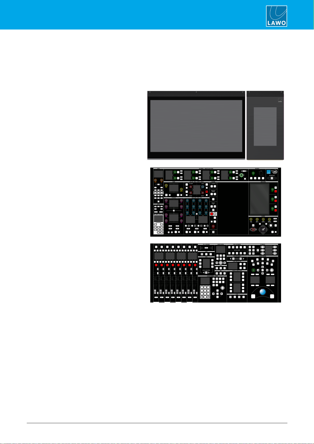
3.5.1 Standard Centre Section
As standard, the centre section is fitted with the following control panels.
1 x Channel Display (978/13)
A high resolution, touch-screen TFT display
(identical to a channel bay). When fitted to the
centre section, the display is known as the
Central GUI.
1 x RTW Panel (978/27)
A special version of the RTW TM9 for Lawo
consoles.
1 x Central Panel Upper (978/21)
with 47 rotary encoders, 12 mini TFT displays, 1
touch-screen display, 1 motorised joystick, 1 XLR
connector, 130 push-buttons.
The panel includes a space for up to two user
panels. Unless otherwise specified, the console
ships with two blanking panels (978/28).
1 x Central Panel Lower (978/20)
with 8 x 100mm motorised faders, 1 rotary
encoder, 13 mini TFT displays, 1 trackball, 207
push-buttons.

mc²96 Installation & Service GuideVersion: 1.0/312/65
3. The Hardware
3.5.2 Xtra Main Faders
Optionally, the Central Panel Lower (978/20) can be replaced by the Xtra Central Panel Lower (978/22) to
increase the number of main faders from8 to 16. To support this option, the Central Panel Upper (978/21) must
be fitted with the Xtra User Panel (978/23) to provide access to the following functions: FC PRESETS, LINK,
ISO, STRIP ASSIGNMENT, FADER USER BUTTON and BUS ASSIGNMENT. This option can be retrofitted to
existing consoles.
1 x Channel Display (978/13)
Identical to standard centre section.
1 x RTW Panel (978/27)
Identical to standard centre section.
1 x Central Panel Upper (978/21)
Identical to standard centre section.
1 x Xtra User Panel (978/23)
with 35 push-buttons.
1 x Xtra Central Panel Lower (978/22)
with 16 x 100mm motorised faders, 1 rotary
encoder, 12 mini TFT displays, 1 trackball, 210
push-buttons.
Replaces the 978/20.
3.5.3 Ethernet Server
Internally, the central bay is fitted with an Ethernet server (mounted behind the display). This can be either a
Bayserver or Gateserver. The differences are described later.
3.5.4 Further Information
All faders and rotary encoders are touch-sensitive.
You can find more information about the individual panels and displays in their data sheets.

mc²96 Installation & Service Guide Version: 1.0/3 13/65
3. The Hardware
3.6 Central User Panel Options
The Central Panel Upper (978/21) can be fitted with up to two Lawo User Panels. If the console is fitted with the
Xtra Main Faders option, then the lower slot must be used for the XTRA USER PANEL (978/23). In all other
cases, the two slots are freely configurable. Unless otherwise specified, the console ships with two blanking
panels (978/28).
User Panel Options
Part No
User Panel Name
Description
978/23
XTRA USER PANEL
Must be fitted to an Xtra Main Faders console.
978/24
40 KEY USER PANEL
40 user-programmable buttons. Two panels can be fitted to provide 80
buttons.
978/25
REVEAL FADER
5 dedicated faders for revealing surround slaves.
978/26
AUTOMATION
Controls for the timecode automation system.
978/28
BLANKING PLATE
Single slot blanking panel.
XTRA USER PANEL
40 KEY USER PANEL
REVEAL FADER
AUTOMATION

mc²96 Installation & Service GuideVersion: 1.0/314/65
3. The Hardware
3.7 Overbridge Metering
The console comes as standard with an RTW TM9 meter. This is a special version of the TM9, designed
specifically for Lawo consoles. If the meter is removed, then a blanking panel (978/29) should be installed.
The meter provides 4 x AES3 inputs for multi-channel metering and 5 x GPI for external control. These are
wired internally to the console's local IO. The default configuration sets the AES3 inputs to follow the MON 1
monitor source selector. Alternatively, signals can be routed directly to the meter using the console GUI.
All other functions are operated via the meter's touch-screen display. Please refer to the documentation from
RTW.
Note that meter includes a temperature-controlled fan to provide cooling at extreme temperatures (>70°C).
Under normal operating conditions, the fan is inactive. When the meter boots up, the fan is tested. This means
that you will hear the fan, momentarily, whenever the control surface power is applied.
mc²96 Installation & Service Guide Version: 1.0/3 15/65
3. The Hardware
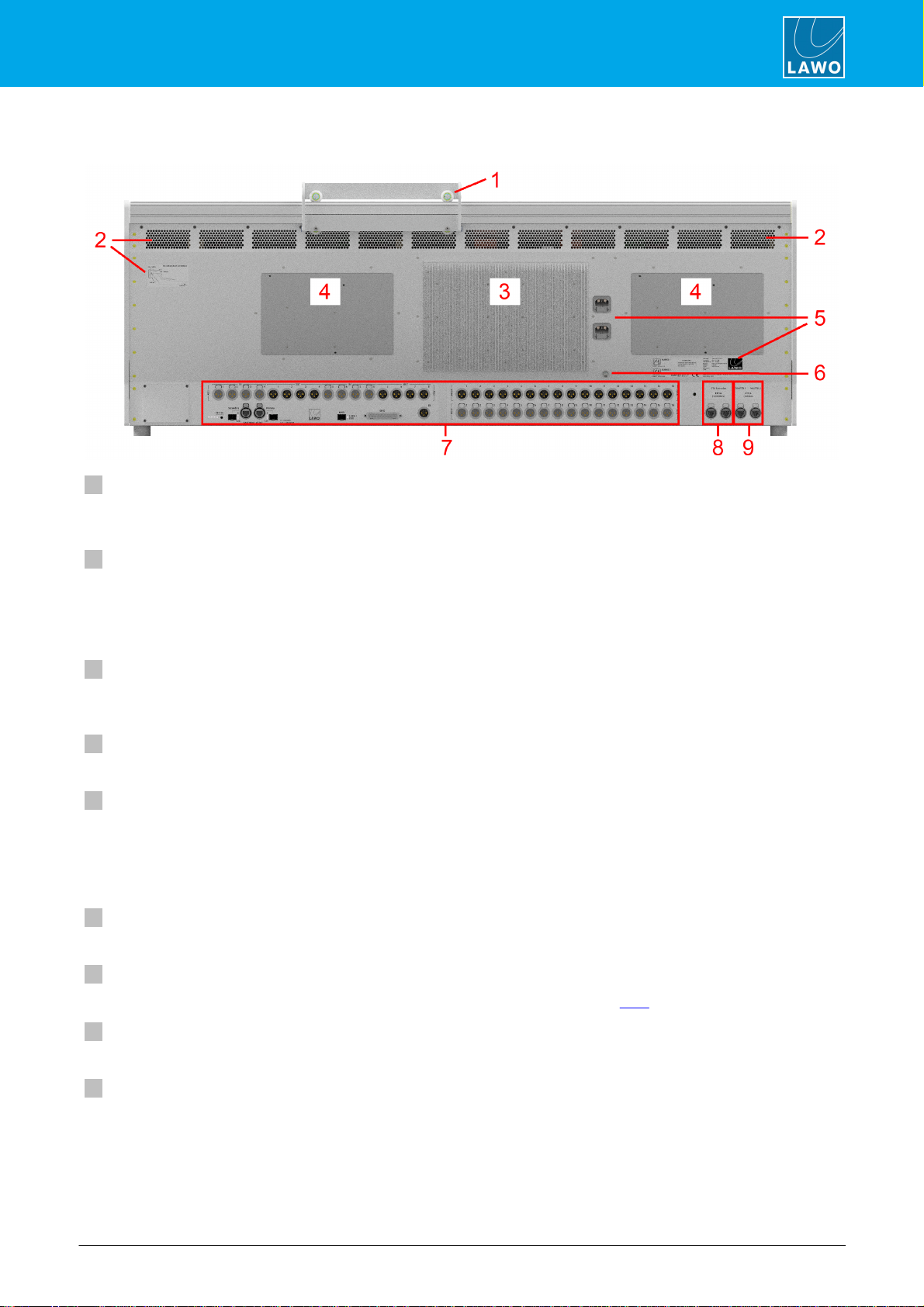
3.8 Console Rear Panel
1 Removable Script Tray (optional)
One or more removable script trays may be ordered. The script tray glides across the top of the frame, and can
be lifted on or off for removal.
2 Ventilation Holes & Sticker
The sticker shows the direction of airflow (required for convection cooling) and the minimum distance
requirements (for installing the frame). It is important that cold air is taken in underneath the console, near the
armrest, and that cold air flows externally upwards across the whole of the rear panel. This is because both the
PSU heat sink (3) and Bayserver back plates (4) will dissipate heat during operation.
3 PSU Heat Sink
Radiates heat from the internal power supplies. The heat sink indicates the location of each PSU block within
the frame.
4 Ethernet Server Back Plates
Radiates heat from the internal Ethernet servers. The back plates indicate their location within the frame.
5 MAINS 1 & 2
The MAINS 1 & MAINS 2 connectors supply AC mains power to the frame. The sticker states the AC mains
requirements.
Depending on the frame size, one or more PSU "blocks" may be installed, each providing main and redundant
power supplies. Therefore, in larger frames you will see more than one set of MAINS connectors.
6 CASE
The CASE grounding screw (M5 x 12mm) should be used to ground the frame.
7 Local IO Connector Panel
Here you will find the connections for the built-in local IO. These are described later.
8 ETH Extension
The first pair of network ports can be used to connect Extender frames.
9 Control Data to/from the Core
The second pair of network ports connect the control surface to the Core.

mc²96 Installation & Service GuideVersion: 1.0/316/65
3. The Hardware
3.9 Ethernet Server Types
Internally, each channel and central bay is fitted with an Ethernet server. In channel bays, the server type is
always the same: a Bayserver. For the central bay, there are two possibilities: either a Bayserver or Gateserver
(supported fromV6.4.0 onwards). This option determines how the control surface connects to the Core and, as
a result, where it can be installed.
·
Bayserver consoles connect directly to the ETHERNET A ports on the Nova73. Since the connection
must be directly-wired, this limits the maximumdistance between the surface and Core.
·
Gateserver consoles connect to the Core via the Management Network. Since this supports Layer 3
routing, this allows the surface to be installed remotely fromthe Core.
The internal and external wiring for each variant are described later.
Externally, there are two ways to determine the central server type: via the start-up screens on the Central GUI,
or the Ethernet connector panel at the rear of the frame.
Start-up Screen (for Central Bayserver)
Start-up Screen (for Central Gateserver)
Rear Connector Panel (if Central Bayserver)
Rear Connector Panel (if Central Gateserver)
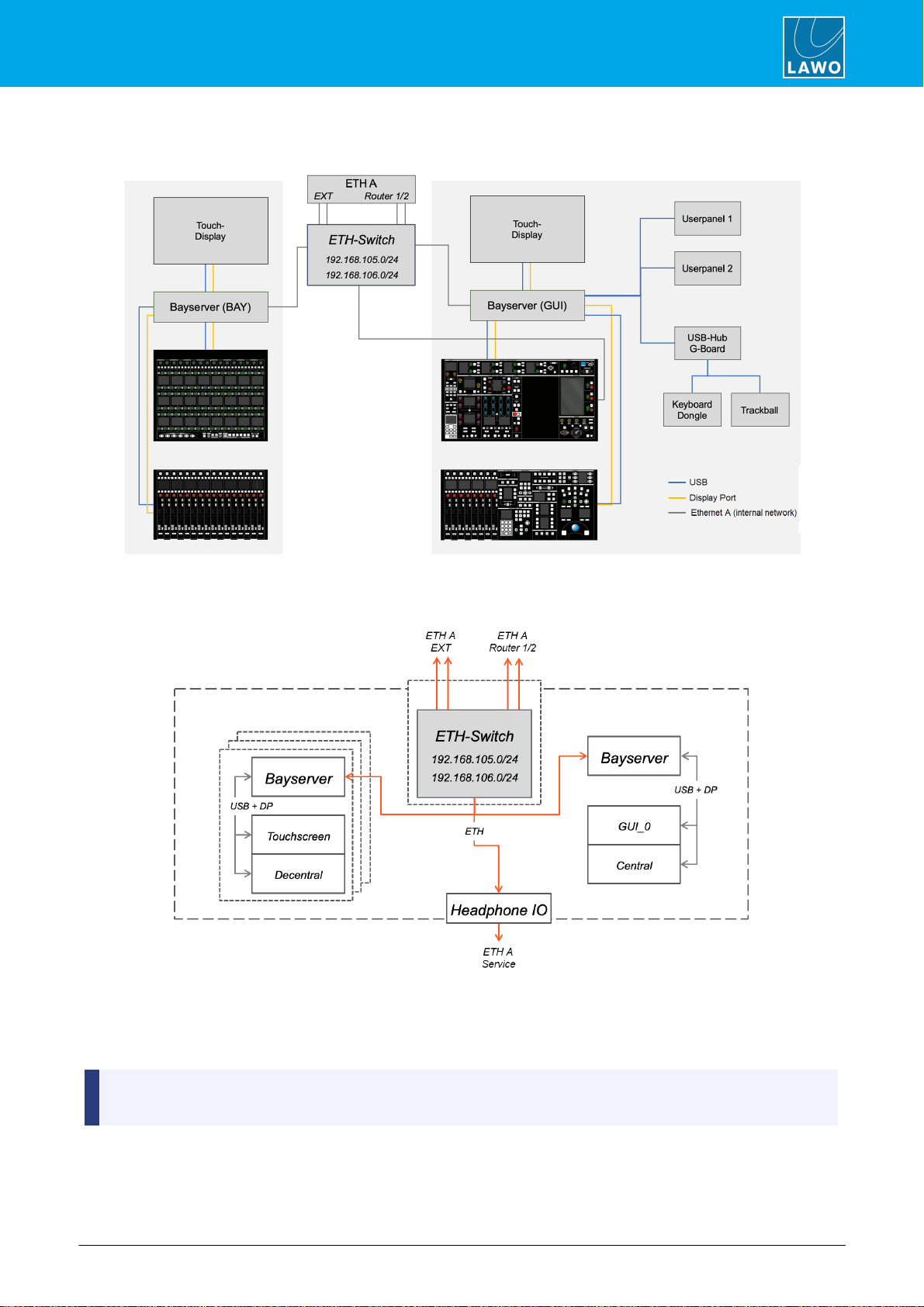
3.10 Control Surface Wiring
Internally, the control surface uses point-to-point connections, within each bay, to provide fault tolerance and
convenient servicing. Any bay or panel can be isolated from the rest of the console, allowing panels and
displays to be replaced during operation.
Firstly, within each bay, individual panels and displays connect to the Ethernet server (mounted behind the
display). In channel bays, the connections are made using both USB and Display Port. In the centre section,
the optional user panels connect via USB only, and there is also a USB hub which connects to the console
keyboard and trackball.
Each server then connects to an Ethernet switch to form what is known as the internal network or ETHERNET
A. On the mc296, the switch also connects to the Central Panel Upper to drive the touch-screen MONITORING
display.
Externally, the following connections are wired from the internal network switch (on all consoles):
·
ETH Extension (rear panel) - to connect extender frames.
·
ETH A (front buffer) - to connect a service computer.
The remaining connections vary, depending on whether the central bay is fitted with a Bayserver or Gateserver.
mc²96 Installation & Service Guide Version: 1.0/3 17/65
3. The Hardware
3.10.1 Internal Wiring for Bayserver Console
Schematics (Bayserver Console)
On a Bayserver console, there are a further two connections from the internal network switch: ROUTER 1 and
ROUTER 2. These must connect directly to the ETHERNET A ports on the Nova73 Router Modules. Only one
connection is essential for operation. If a second Router Module is fitted, then a second connection should be
made to support redundancy.
The control surface must be connected to the mc2control system (via ETHERNETA) in order to boot.
Therefore, to start the system, both the control surface and Nova73 must be powered.
mc²96 Installation & Service GuideVersion: 1.0/318/65
3. The Hardware
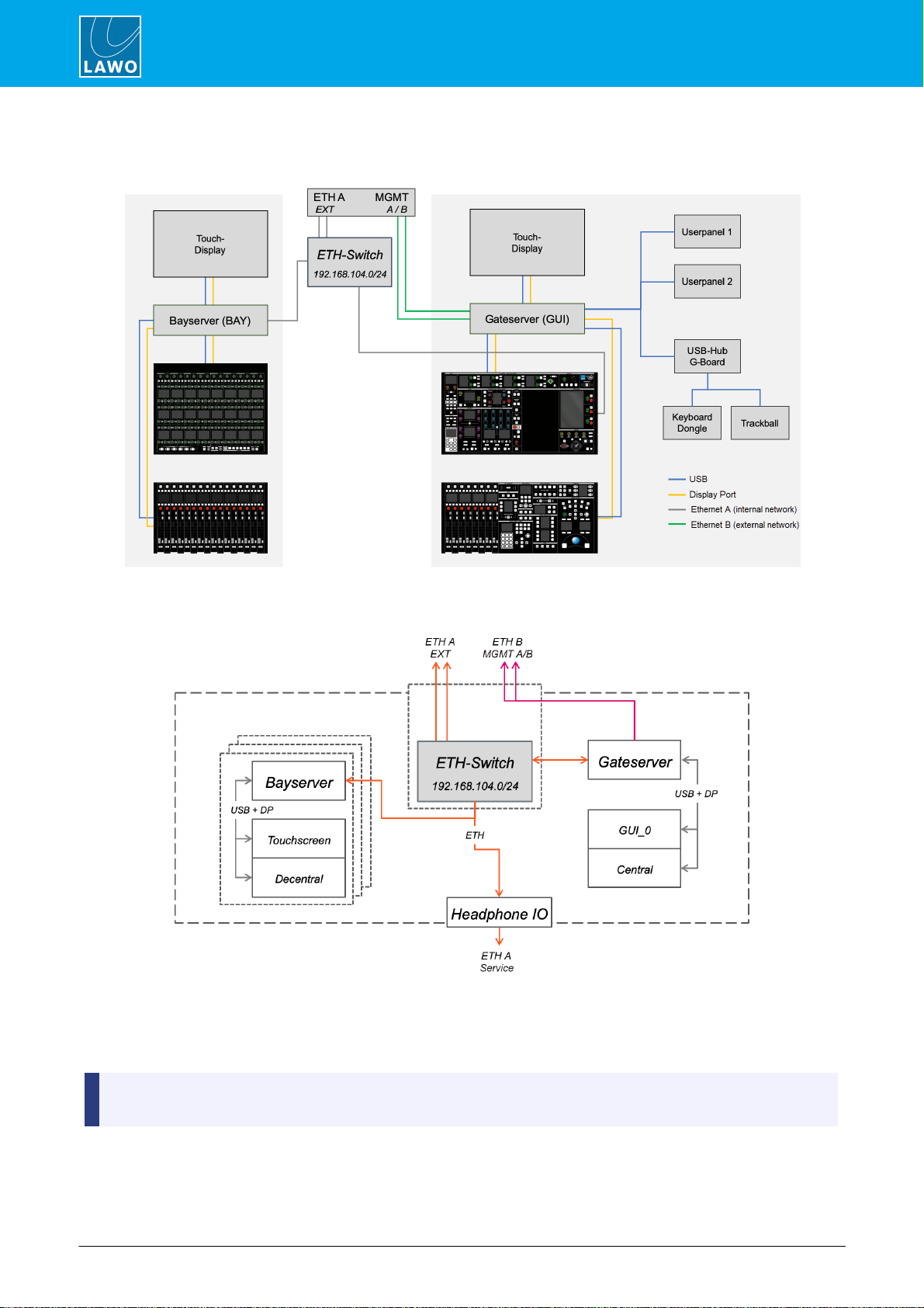
3.10.2 Internal Wiring for Gateserver Console
Schematics (Gateserver Console)
On a Gateserver console, there are a further two connections which come from the Gateserver: MGMT A and
MGMT B. These must connect to the same Management Network as the Core's control ports (e.g. ETHERNET
B if the Core is a Nova73). Only one connection is essential for operation. A second connection can be
installed to support redundancy.
A Gateserver console can boot on its own once power is supplied to the control surface. To become fully
operational, there must also be a valid network connection to the Core.

mc²96 Installation & Service Guide Version: 1.0/3 19/65
3. The Hardware
3.10.3 Additional Notes for Gateserver Consoles
The Gateserver provides a more sophisticated computing engine that can boot on its own once power is supplied
to the control surface. To achieve this, the Gateserver has its own SSD storage containing the boot image. This
must be updated separately using the mxUpdater utility (included with mxGUI).
After a successful boot, the Gateserver connects automatically to its partnered Core (by creating a VPN
connection between the Gateserver and mc2control system). If there is no connection available, then the
console will show "disconnected" screens. Once a valid network connection is established, the screens update to
their "connected" state. This indicates that the console is ready for operation.
For the console to become fully operational, there must be a valid network connection between the
Gateserver and mc2control system.

mc²96 Installation & Service GuideVersion: 1.0/320/65
4. Installation
4. Installation
This chapter describes how to install the control surface.
4.1 Unpacking
If the control surface comprises more than one frame, then each frame is delivered separately. All included
accessories are shipped in the "Accessories" box. Any optional components are delivered in their own packing
boxes.
Please check the contents of the shipping boxes, and in the event of any transport damage, contact your local
Lawo representative or email support@lawo.com.
4.2 Packing List
Included
The following items are included with the control surface (in the "Accessories" box):
·
2 x 2m IEC power cables (country-specific) - to connect mains power to the frame. If the surface
contains more than one PSU block, then additional IEC power cables are supplied.
·
1 x Logitech wireless keyboard + USB dongle - to be installed as the console keyboard. The USB
cable is included for charging purposes.
·
1 x dust-cover - to protect the console when not in use.
·
1 x tool case + tools - for performing service procedures.
·
1 x USB memory card - containing the latest software and configuration files.
If you have ordered the studio version, then this comes with the console stand: 2 x detachable legs + mounting
plates.
Optional
The following items must be ordered separately.
·
SFP modules - for the MADI and RAVENNA/AES67 ports.
·
Removable Script Tray (978/68).
Table of contents
Other LAWO Dj Equipment manuals


