LAWO crystal User manual


Copyright
All rights reserved. Permission to reprint or electronically reproduce any document or graphic in whole
or in part for any reason is expressly prohibited, unless prior written consent is obtained fromthe Lawo
AG.
All trademarks and registered trademarks belong to their respective owners. It cannot be guaranteed that
all product names, products, trademarks, requisitions, regulations, guidelines, specifications and norms
are free from trade mark rights of third parties.
All entries in this document have been thoroughly checked; however no guarantee for correctness can
be given. Lawo AG cannot be held responsible for any misleading or incorrect information provided
throughout this manual.
Lawo AGreserves the right to change specifications at any time without notice.
© Lawo AG, 2021

3/459
Table of Contents
crystal User Manual Version: 6.6.0/2
Table of Contents
1. Introduction ......................................................................................................................................... 4
2. Important Safety Instructions ................................................................................................................ 5
3. The Hardware ..................................................................................................................................... 6
4. The Standard Configuration ................................................................................................................ 15
5. Installation ......................................................................................................................................... 22
6. SystemSetup .................................................................................................................................... 40
7. Operation .......................................................................................................................................... 57
8. Configuring crystal ........................................................................................................................... 126
9. Audio IO ......................................................................................................................................... 138
10. Audio MixEngine ............................................................................................................................. 161
11. Audio Utilities ................................................................................................................................... 222
12. Routing Matrix.................................................................................................................................. 226
13. Intercom ......................................................................................................................................... 233
14. Control Surface Configuration ........................................................................................................... 258
15. Configuring the Snapshots System .................................................................................................... 281
16. Connecting a VisTool MK2 PC .......................................................................................................... 289
17. Key Panel Control ............................................................................................................................ 319
18. GPIO .............................................................................................................................................. 325
19. Configuring Custom Logical Behaviour .............................................................................................. 339
20. Networking Options .......................................................................................................................... 373
21. The Web UI ..................................................................................................................................... 401
22. The Firmware Update Tool ................................................................................................................ 409
23. Maintenance .................................................................................................................................... 420
24. Troubleshooting ............................................................................................................................... 431
25. Appendices ..................................................................................................................................... 436
26. Glossary ......................................................................................................................................... 456

crystal User ManualVersion: 6.6.0/24/459
1. Introduction
1. Introduction
Welcome to crystal.
About this Manual
This document describes all aspects of the system, including the installation, configuration, operation and
maintenance.
Look out for the following which indicate:
Notes - points of clarification.
Tips - useful tips and short cuts.
Attention - alert you when an action should always be observed.
Further Information
Mechanical drawings and data sheets (including weights and dimensions) are available from the Download-
Center (after login).
Lawo User Registration
For access to the Downloads area and to receive regular product updates, please register at:
www.lawo.com/registration.

crystal User Manual Version: 6.6.0/2 5/459
2. Important Safety Instructions
2. Important Safety Instructions
Please observe all of the instructions provided in the "General Safety Information for Lawo Equipment" booklet
delivered with your devices. Double-click here to open the information as a pdf.


crystal User Manual Version: 6.6.0/2 7/459
3. The Hardware
3.1 System Components
A complete system consists of up to four components:
·
crystal Control Surface (essential) – available in five main frame layouts.
·
Compact Engine (essential) – all audio interfacing, routing, control and signal processing.
·
VisTool MK2 (optional) – runs on an external PC to provide real-time displays and touch-screen control.
·
Key Panels (optional) – a range of panels offering additional keys and talkback control.
crystal User ManualVersion: 6.6.0/28/459
3. The Hardware
3.2 Controls Overview
Each control surface consists of at least one Fader Module (with 4 fader strips) and either one or two Central
Modules depending on the frame size.
Some of the control functionality is fixed (system-defined), while some is programmable by the configuration.
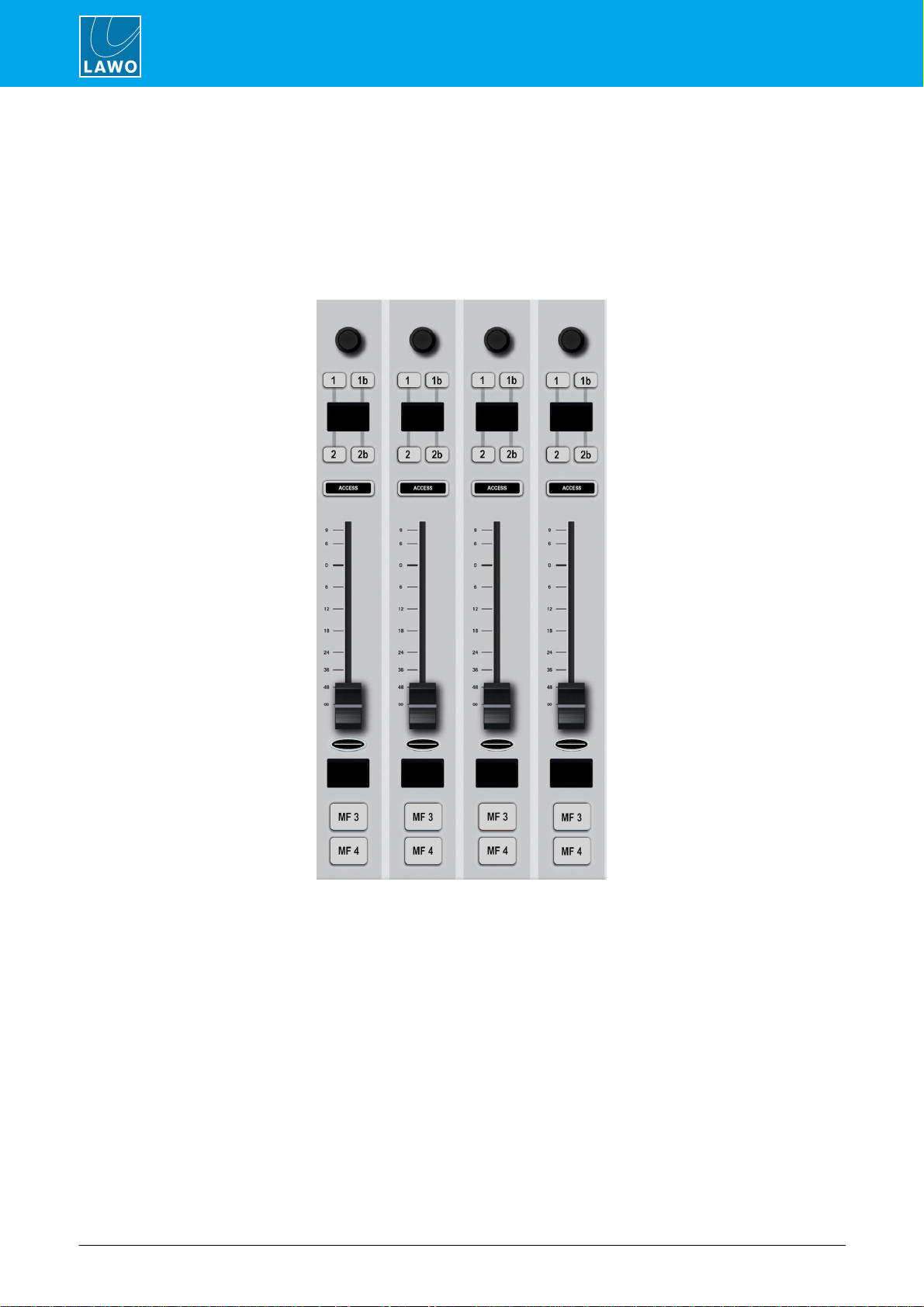
3.2.1 Fader Module (951/41-10)
Fader Module
Each Fader Module provides four identical fader strips, each with an ACCESS key, 100mm manual fader,
backlight and label display.
The upper section includes a rotary control and four small MF Keys (1, 1a, 2, 2b). Their functions are labeled by
the OLED displays.
Belowthe label display are two large MF Keys (3, 4) with foil-printed labels.
All MF Keys are defined by the configuration.

crystal User Manual Version: 6.6.0/2 9/459
3. The Hardware
3.2.2 Central Module (951/41-20)
Central Modules (left & right)
The 4-fader crystal has one Central Module, while all other frame sizes include two (as shown above).
The two stereo peak and correlation meters (A and B) are defined by the configuration.
On the left module, the 8 Function Buttons (INP, DYN,LIM, etc.) are defined by the system. They provide
access to DSP parameter control, bus assign and snapshot save/recall.
On the right module, the same physical keys operate as MF Keys (17 to 24) with foil-printed labels.
Both modules include two rotary encoders (VCAs1, 2) and more MF Keys (1 to 16) with foil-printed labels.
All MF Keys and VCAs are defined by the configuration.
3.2.3 Programmable Functions
Programmable controls, such as MF Keys and VCA encoders, are defined by the configuration stored on the
Compact Engine. They can be edited using the ON-AIRDesigner software, allowing you to change the operation
as required.
In most cases, the MF Keys are labeled by foil-printed labels and, by default, the control surface ships with the
labels for the standard template functions. If you change the MF Key functionality, then you will need to
exchange the foil-printed labels. Printed sheets with the most common labels are included with each control
surface frame.
crystal User ManualVersion: 6.6.0/210/459
3. The Hardware
3.3 Control Surface Variants
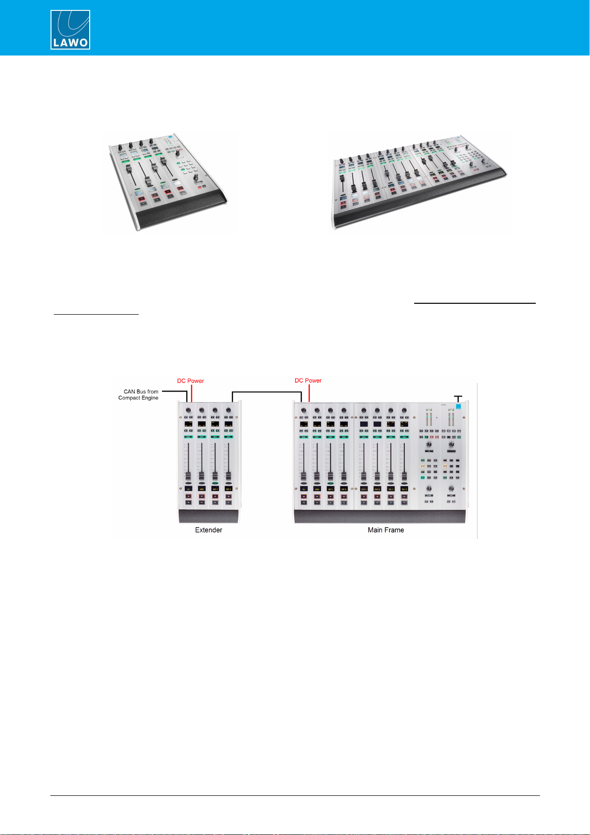
4-fader single frame
12-fader single frame
crystal can exist as a single or split-frame control surface.
A choice of five main frame layouts are available, with the option to add an extender module to increase the
fader count or create a split-frame surface.
In total, the control surface can include any number of extenders as long as the maximum number of faders
does not exceed 24.
Each frame connects to the Compact Engine via CANbus, and is powered from its own 12V DC power supply
(included). All frames include CAN IN and CAN OUT connectors for easy daisy-chaining. In each case, the
CAN bus address of a module defines its functionality. Thus, frames can be wired in any order.
Split-frame Example
crystal User Manual Version: 6.6.0/2 11/459
3. The Hardware
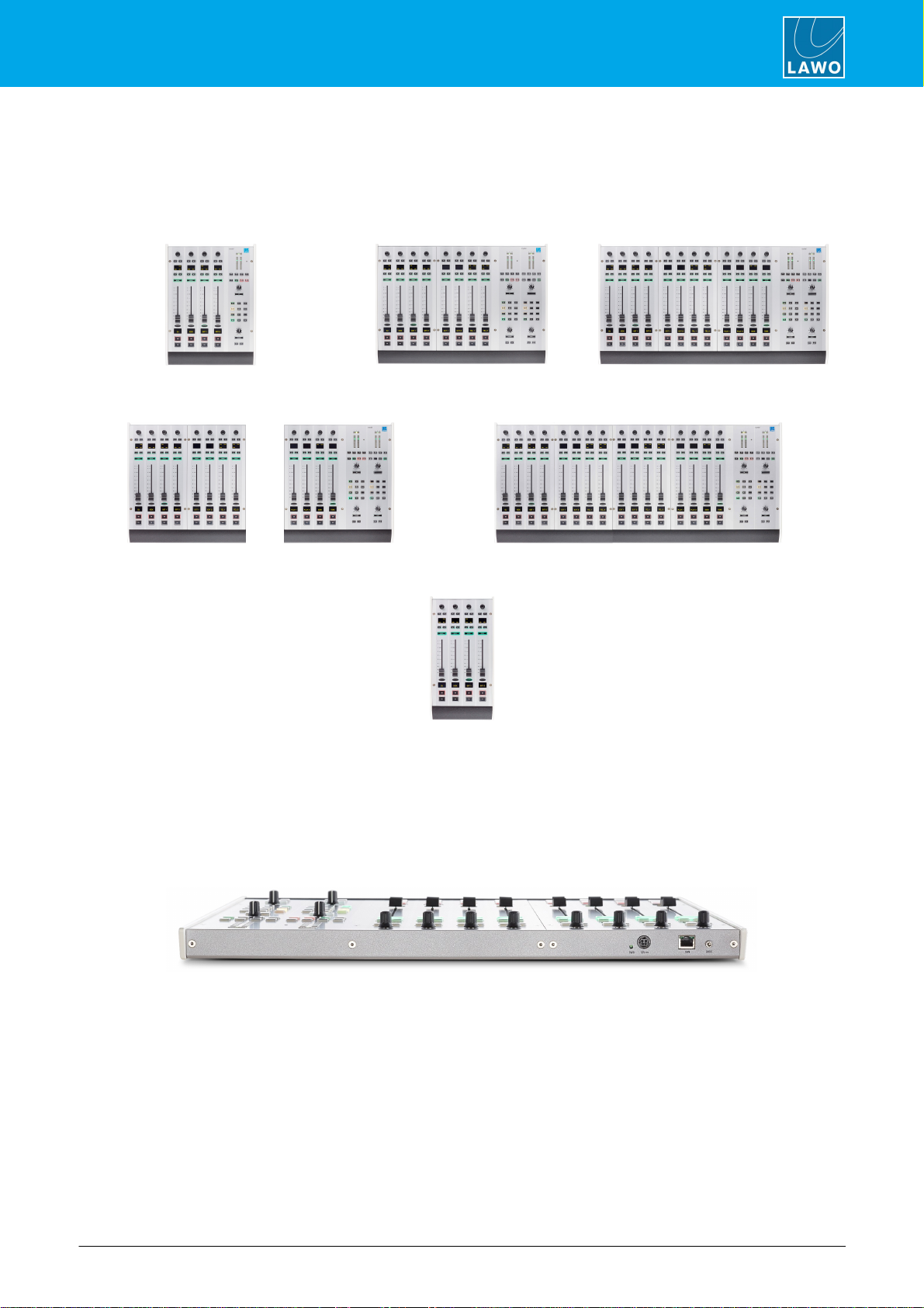
3.3.1 Frame Layouts
Five main frame layouts are available plus the 4-fader extender. Note that the 4-fader main frame supports a
single Central Module, while all other sizes include two.
4-fader
8-fader
12-fader
12-fader split
16-fader
4-fader extender
3.3.2 Placement Options
crystal is designed to be mounted on a table top surface.
All connectors are positioned along the top edge, so you must make sure that these are accessible:
8-fader Surface (top edge)

crystal User ManualVersion: 6.6.0/212/459
3. The Hardware
3.4 The Compact Engine
The 19”/1RU Compact Engine contains the signal processing, control system and routing matrix. It also handles
all audio, control and external Wordclock connections.
3.4.1 Front View
1 Status Display & Menu Control
The front panel display shows local device parameters such as the IP address. You can use the >> and OK
buttons to navigate through the menus.
2 RESET button
Press this button to perform a warm start. The button is recessed to prevent accidental operation.
A warm start will reboot the device. Do NOT perform a warm start while live on air!
3 MADI 1 to 4
The Compact Engine can be delivered with 0, 2 or 4 external MADI ports to connect multi-channel digital audio.
Each port supports 64 bi-directional channels.
The odd/even port pairs (1/2, 3/4) can be configured to operate as main and redundant connections.
4 ETHERNET
The ETHERNET port connects other devices to the Compact Engine control system. Applications include remote
control via TCP/IP; networking to other products; updating firmware and uploading a configuration.
5 CAN
The CAN bus port connects to the control surface frame(s).
6 RS 422
The serial port can be used for debugging. It is usually left unconnected.
7, 8 Expansion Slots x 2 - additional IO
The two expansion slots can be fitted with any of the following IO cards:
·
LINE IO (952/31) - 8 x line level in + 8 x line level out.
·
AES3 IO (952/32) - 4 xAES3 in (with SRC) + 4 xAES3 out (with SRC).
·
MIC/LINE IO (952/36) - 4 x mic/line in + 4 xline level in.
·
RAVENNA IO (952/38) - 2 x AoIP ports, supporting either 8 in/out or 64 in/out with the internal MADI
bridge option.
Cards can be fitted to either slot position, but to use all 64 channels of a RAVENNA IO card it must use the left
slot (7) to support the internal MADI bridge.
IO cards must NOT be exchanged while the frame is powered, as to do so may damage the card and/or
Compact Engine.

crystal User Manual Version: 6.6.0/2 13/459
3. The Hardware
3.4.2 Rear View
9 Analog & Digital IO
The following audio connections are always included.
·
HEADPHONE 1 & HEADPHONE 2 - two stereo headphone outputs.
·
LINE OUTPUT- 8 x line level outputs.
·
MIC/LINE INPUT - 4 x mic/line in + 4 xline level in.
·
AES3 INPUT - 4 x AES3 inputs.
·
AES3 OUTPUT- 4 x AES3 outputs.
10 GPIO
This connector provides 8 x GPI (optocouplers) and 8 x GPO (silent and self-healing relays) for local signaling
and switched functions.
11 WCLK IN & OUT
WCLK IN can be used to connect an external sync reference. The sync reference options are MADI, WCLK IN,
AES3 or Internal.
WCLK OUT always provides an output of the current system reference.
12 CASE
The CASE grounding screwshould be used to ground the frame.
13 12V DC & AC MAINS Inputs
Every device comes with dual power feeds: AC and DC. To use the DC input, you will need the external 12V DC
power supply. This is optional and must be ordered separately.
If both inputs are connected, then the two feeds provide main and redundant power.
The Compact Engine MUST be connected to the mains using the power cable supplied with the system.


crystal User ManualVersion: 6.6.0/216/459
4. The Standard Configuration
4.1 Introduction
To make the console easy to operate ‘out of the box’, the Compact Engine is delivered with a standard
configuration. This defines how many sources and summing buses you have, where to connect your audio
devices, the signal processing for each source channel, what functions are programmed onto the MF keys, and
so on.
The standard configuration can be modified using a software application called the ON-AIR Designer. The later
chapters in this manual describe the possible configuration options. For more information on using the tool,
please refer to the "ON-AIR Designer User Guide".
If you are using VisTool MK2, then there is an accompanying VisTool configuration which can be operated using
a standard VisTool license. This is described later in the Operation chapter. For more information on installing
VisTool MK2, and modifying its configuration, please refer to the "VisTool MK2 User Guide".
The standard configuration files are available from the Downloads area at www.lawo.com (after Login). Please
note that there is a separate ON-AIR Designer file for each frame size. The "vistool_crystal" project can be used
with any of the ON-AIR Designer files.
crystal User Manual Version: 6.6.0/2 17/459
4. The Standard Configuration
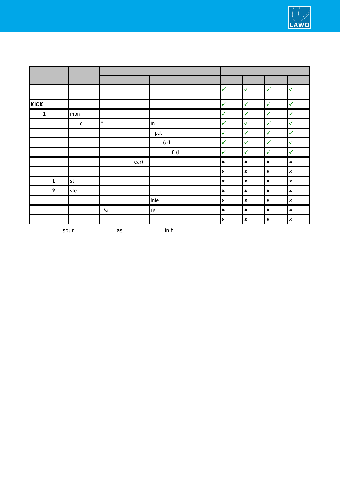
4.2 Available Sources
The table below describes the available sources.
Source Name
Format
Physical Input
DSP Resources
Connector
Input No. / StreamName
EQ
Dyn
Lim
DE/AMx
DJ
mono
MIC/LINE INPUT
(rear)
Input 1 (mic/line)
ü
ü
ü
ü
KICK
mono
"
Input 2 (mic/line)
ü
ü
ü
ü
GST 1
mono
"
Input 3 (mic/line)
ü
ü
ü
ü
GST 2
mono
"
Input 4 (mic/line)
ü
ü
ü
ü
TEL 1
mono
"
Input 5 (line)
ü
ü
ü
ü
TEL 2
mono
"
Input 6 (line)
ü
ü
ü
ü
LINE
stereo
"
Inputs 7&8 (line)
ü
ü
ü
ü
EXT 1
stereo
AES3 INPUT (rear)
Inputs 1&2
û
û
û
û
EXT 2
stereo
"
Inputs 3&4
û
û
û
û
PLAYER 1
stereo
"
Inputs 5&6
û
û
û
û
PLAYER 2
stereo
"
Inputs 7&8
û
û
û
û
TONE
mono
n/a
Internal Test Tone
û
û
û
û
DUMMYm
mono
n/a
n/a
û
û
û
û
DUMMYs
stereo
n/a
n/a
û
û
û
û
The DUMMY sources are included as a starting point (in the configuration) for additional sources to the system.

crystal User ManualVersion: 6.6.0/218/459
4. The Standard Configuration
4.3 Available Buses
The tables below describes the available summing and conference buses.
Summing Bus Name
Format
Pickup Point
DSP
Outputs
PGM
stereo
post-fader
Lim
see Default Audio.
REC
stereo
pre or post-fader
Lim
"
AUX
stereo
pre or post-fader
Lim
"
PFL
stereo
pre-fader
û
PFL appears on the SPEAKER and DJ
HP outputs.
Conf Bus Name
Format
Pickup Point
Outputs
CB DJ
mono
post-fader N-1 (mix minus) for MIC 1
(DJ)
see Default Audio.
CB T1
mono
post-fader N-1 (mix minus) for TEL 1
"
CB T2
mono
post-fader N-1 (mix minus) for TEL 2
"
CB LN
mono
post-fader N-1 (mix minus) for LINE
"

crystal User Manual Version: 6.6.0/2 19/459
4. The Standard Configuration
4.4 Default Audio Assignments
The tables which followlist the default audio assignments for the inputs and outputs.
For the inputs, the source assignments are fixed and cannot be changed by the user. Instead, you can choose
which inputs are active in the mixby changing the fader strip assignments on the surface.
For the outputs, the configuration loads the default audio assignments.
4.4.1 Analog Inputs
MIC/LINE INPUT (Compact Engine rear panel)
Input Number
Source Name
Format
1
DJ
mono
2
KICK
mono
3
GST 1
mono
4
GST 2
mono
5
TEL 1
mono
6
TEL 2
mono
7/8
LINE
left/right
4.4.2 Analog Outputs
LINE OUTPUT (Compact Engine rear panel)
Output Number
Format
Default Audio from
1/2
left/right
PGM
3/4
left/right
MON CR
5
mono
TEL 1 n-1
6
mono
TEL 2 n-1
7/8
left/right
ISDN (LINE) n-1
HEADPHONE SOCKETS (Compact Engine rear panel)
Output Number
Format
Default Audio from
HEADPHONE 1
left/right
MON DJ
HEADPHONE 2
left/right
MON GUEST

crystal User ManualVersion: 6.6.0/220/459
4. The Standard Configuration
4.4.3 Digital Inputs
AES3 INPUT (Compact Engine rear panel)
Input Number
Source Name
Format
1/2
EXT 1
left/right
3/4
EXT 2
left/right
5/6
PLAYER 1
left/right
7/8
PLAYER 2
left/right
4.4.4 Digital Outputs
AES3 OUTPUT (Compact Engine rear panel)
Output Number
Format
Default Audio from
1/2
left/right
PGM
3/4
left/right
REC
5/6
left/right
AUX
7/8
left/right
FOLLOW MON CR
Table of contents
Other LAWO Dj Equipment manuals


