LAWO mc266 Operation instructions
mc²66
Tutorial
Version: V1.3/0
Edition: 05-12-14

Co
p
yright
All rights reserved. Permission to reprint or electronically reproduce any document or graphic in
whole or in part for any reason is expressly prohibited, unless prior written consent is obtained
from the Lawo AG.
All trademarks and registered trademarks belong to their respective owners. It cannot be
guaranteed that all product names, products, trademarks, requisitions, regulations, guidelines,
specifications and norms are free from trade mark rights of third parties.
All entries in this document have been thoroughly checked; however no guarantee for correctness
can be given. Lawo AG cannot be held responsible for any misleading or incorrect information
provided throughout this manual.
Lawo AG reserves the right to change specifications at any time without notice
© Lawo AG, 2005

Table of Contents
mc²66 V1.3/0 5/ 68
Table of Contents
TUTORIAL 2
TABLE OF CONTENTS 5
PREFACE 8
About This Manual 8
Conventions 8
Headings 8
Instructions and Results 8
Marginal notes 8
Action Buttons 9
CHAPTER 1: TUTORIAL 11
Welcome 11
Control Surface Overview 11
Signal Flow 12
The Power of Layering 13
Integrated Digital Routing Matrix 14
Console Reset 15
Timecode Automation 16
ACCESS CHANNEL/ASSIGN and SCREEN CONTROL 17
The ACCESS CHANNEL/ASSIGN control panel 18
SCREEN CONTROL 21
Entering Names from the Keyboard 26
Getting Started 27
Switching on the Power 27
Loading a Setup Production 28
Interrogating the Channel Fader Strips 30
Switching Banks and Layers 30
Creating Your Own Configuration 32
Assigning Channels to Fader Strips 32
Source Routing 35
Bus Assignments 37
Control Room Monitoring 38
AFL & PFL Monitoring 39
Routing Sources to Multiple Channels 40
Controlling Microphone Pre-amplifier Settings 42
Saving Your Settings 43
Saving a New Production 43
Renaming the Production 45
Updating the Production 46
Configuring Audio Sub Group Masters 47
Re-assigning Channels to Groups 47
Monitoring the Group Output 50
Creating Stereo Channels or Masters 51

Table of Contents
6/ 68 V1.3/0 mc²66
Routing Masters to Output Destinations 52
Using Auxiliary Sends 54
Creating a Mix Minus (N-1) 55
Configuring the Mix Minus Auxiliary Sends 55
Activating the Mix Minus Sends 58
Using VCA Grouping 59
Assigning VCA Masters to the Control Surface 59
Assigning Channels to a VCA Master 60
Applying Signal Processing 61
Using the 4-band Equaliser 63
Using the High and Low Pass Filters 64
Setting a Compressor 65
Inserting Channel Delay 66
Inserting Outboard Processing 66
Assigning the Fader Strip Free Controls 69

Table of Contents
mc²66 V1.3/0 7/ 68
Preface
8/ 68 V1.3/0 mc²66
Preface
About This Manual
Before we guide you through the operation of the mc266 broadcast production console, first a
few words about this manual.
Chapter 1 provides a step-by-step tutorial to common console operations. If you are new to
the console, please read this chapter first.
Chapters 2 to 8 cover each area of operation in greater detail. Use the Table of Contents at the
beginning of the manual or Index Directory (Page Fehler! Textmarke nicht definiert.) to locate
help on a particular topic.
Appendices, technical data and the index directory are provided at the end of the manual.
Conventions
Throughout this manual we will be using a number of conventions:
Headings
Every new topic is clearly identified in large, bold font.
Instructions and Results
Specific operational procedures are written as a sequence of numbered instructions which
guide you through the task. The result of the operation is written in italic letters giving you the
chance to identify errors at an early stage. For example:
1. To make the route press the CONN (Connection) soft key located above the trackball.
The Signals display updates with a green line showing the route between your source and
destination.
Marginal notes
The following marginal notes are used to draw your attention to:
User tips Notes

Preface
mc²66 V1.3/0 9/ 68
Action Buttons
We will also be using some conventions to help distinguish explanatory text from the text
referring to items on the console:
Silk screened text on the console’s front panel is referred to in UPPERCASE and button cap
engravings are written in bold – for example, press the INPUT button located on the ACCESS
CHANNEL/ASSIGN control panel in the centre section of the console.
On-screen buttons which action a function and descriptive text on the console displays are
both referred to in bold. For these, you will be advised when an on-screen button actions a
function – for example, select the Mix minus box to choose a mix-minus auxiliary.


Tutorial
mc²66 V1.3/0 11/ 68
Tutorial
Welcome
Welcome to the mc266 Broadcast Production Console, Lawo’s
purpose designed solution for on-air and live-to-tape broadcast
operations.
The mc266 is a very flexible mixing console with the power to
deal with a range of production types. This tutorial guides you
step-by-step through some of the principal console operations.
Each topic is given a reference to more detailed information in
the chapters to follow.
Control Surface Overview
The mc266’s control surface is constructed in 8-fader sections,
with typical sizes scaling from 16 channel faders + 8 masters up
to 48 channel faders + 8 masters.
Within each channel section, you will find 8 dedicated fader
strips providing basic channel controls, such as level, mute and
monitoring. Four assignable rotary controllers (free controls) offer
additional local channel control. A fifth upper controller is
dedicated for input gain. In addition, every 8-fader channel
section houses a high resolution TFT display providing feedback
on channel metering and bus assignments.
Any DSP channel may be accessed from the Central Control
Section offering direct control of
all
settings – input control,
signal processing, panning, level, AFL/PFL and auxiliary sends.
The Main display works in parallel with these controls providing
clear visual feedback on the channel’s settings as you adjust
them. Below the Central Control Section you will find eight
additional main fader strips for dedicated masters.
On the right hand side of the centre section are the automation
and snapshot/sequence controls; the monitoring control panels;
the user panel which may house functions such as
communications, machine control, etc.; and the ACCESS
CHANNEL/ASSIGN control panel for bus and fader strip
assignment, layering access, joystick and centre screen
navigation.

Tutorial
12/ 68 V1.3/0
Signal Flow
The mc266 provides the flexibility to configure as many input
channels, monitor return channels, groups, sums (main mix
outputs) and auxiliary sends as the production requires. In
addition, these resources can be allocated full signal processing
or reduced signal processing enabling you to assign EQ,
Dynamics, etc. to both inputs and outputs such as groups, sums
and auxiliary sends.
For any given hardware specification, you may choose from a
variety of DSP configurations designed to meet a variety of on-
air, recording and post production needs. Configurations may be
changed at any time, making it easy to modify the mix structure
if you decide, for example, that the production requires some
additional groups. The choice of DSP configuration is stored and
recalled in the console production, independently of snapshots.
This allows you to use snapshots to recall settings while on-air
without re-configuring DSP resources.
The number of full and reduced processing channels, and their
configuration, is determined by three factors – the hardware
specification of the console, the choice of sampling rate and your
choice of DSP configuration.
Fully Featured Channel
Signal Flow:
INMIX
DELAY
DIGIAMP
FILTER
EQ
IMAGE
DYN
INSERT
FADER
DIROUT
BUS
32AUX
INMIX
DELAY
DIGIAMP
FILTER
EQ
IMAGE
DYN
INSERT
FADER
DIROUT
BUS
32AUX

Tutorial
mc²66 V1.3/0 13/ 68
The Power of Layering
The console’s control surface includes both channel and main
fader strips. Any fader strip may control any type of channel -
input, monitor return, group, sum, auxiliary or VCA master –
allowing you to lay out your source channels and output masters
where you want them.
In addition, the physical size of the control surface does not need
to restrict the number of processing channels available.
Regardless of the size of the control surface, the number of audio
processing channels may be scaled by fitting more DSP cards
within the HD core. The extra channels are then accessed by
paging the console’s fader strips using banks and layers:
Up to six control surface banks may be configured; think of each
fader bank like a separate console, with fast global switching
between banks. They may be used, for example, to access
different sets of music channels during a live entertainment
show, or to separate different location sources during a sports
production.
Within each of the six banks, each fader strip has two layers –
Layer 1 and Layer 2. Layers can be switched either globally or
individually, making them ideal for fast access to related sources.
For example, assign a main microphone channel to Layer 1 and a
backup microphone channel to Layer 2, or assign your input
channels to Layer 1 and monitor return channels to Layer 2.
By isolating fader strips from the bank and layer switching, you
can decide which channels require dedicated access (e.g.
presenter’s microphones) and which can be hidden from view
until required (e.g. audience microphones). This enables consoles
of a modest size to handle very large productions.
In addition to controlling onboard DSP, fader strips may be
assigned to General Purpose Channels (GPCs), allowing control
of parameters within external devices via MIDI. For example, to
control camera microphone levels using a MIDI to VCA converter
or to control faders and other parameters within an external
DAW.
Depending on which snapshot is currently loaded, you may be
sitting in front of a fully configured control surface with sources
and fader strips pre-assigned, or your console may look blank
waiting for fader strips to be configured.
Channel Fader Stri
p
s
Tutorial
14/ 68 V1.3/0
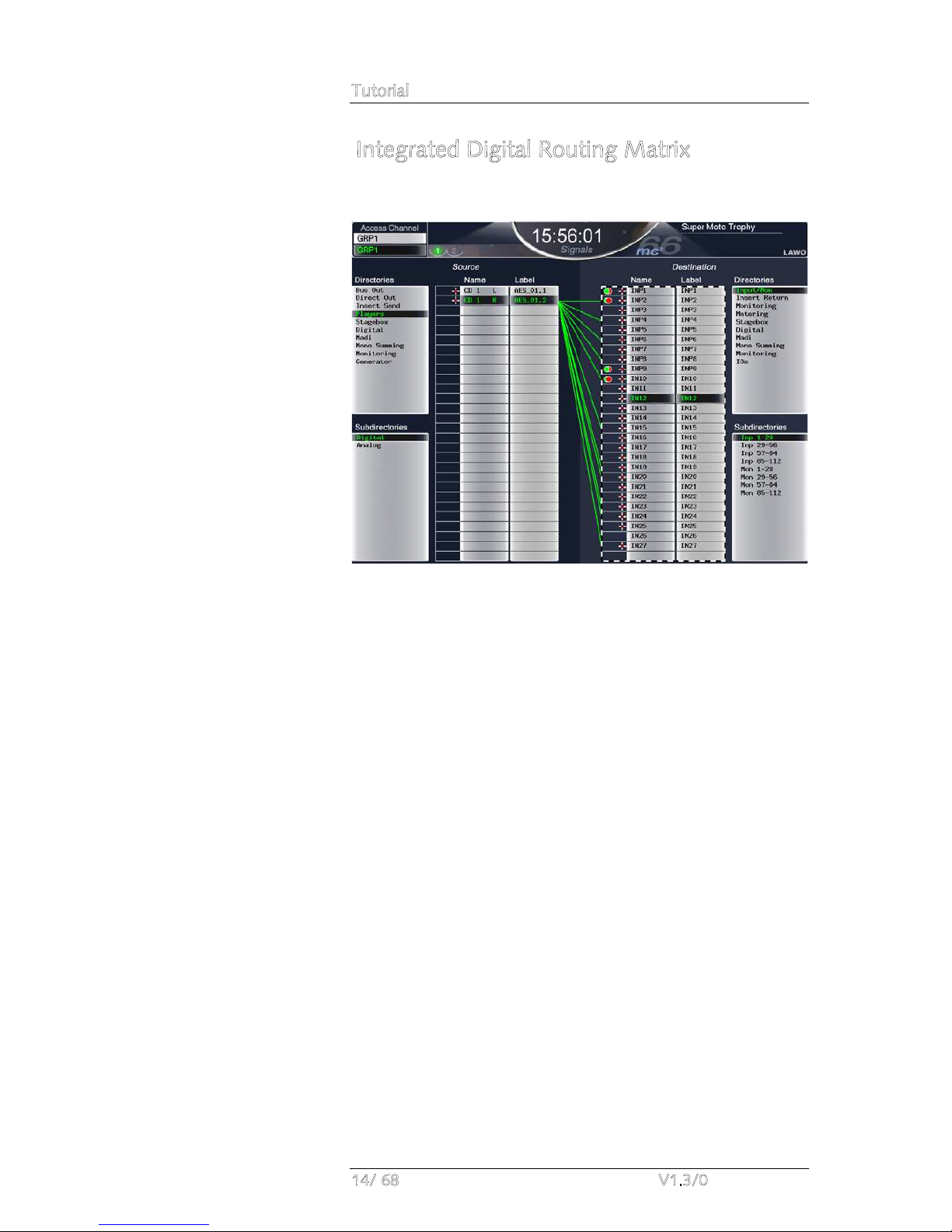
Integrated Digital Routing Matrix
In addition to powerful mixing features, the console includes an
integrated digital routing matrix:
Any source may be routed to any channel, and any output mix
routed to any destination. In addition, you may route sources
directly to destinations, for example to feed a Mic/Line input to
an AES output for archive recording purposes.
Perhaps the most important feature of the routing matrix is that
all routes may be stored and recalled from a snapshot, reducing
the amount of manual patching within the installation and saving
hours of set up time!

Tutorial
mc²66 V1.3/0 15/ 68
Console Reset
One of the major benefits of the mc266 is the ability to store and
recall all the settings required for a live show or type of
application.
Productions form the top level for user data storage and store
all
the settings required for a production or type of job. Productions
may be recalled at any time, reducing the amount of setup time
required before repeat or similar shows. Productions store low
level settings, such as the DSP configuration, SRC settings,
System display options and Metering display setup, in addition to
snapshots, sequences and automation mixes. Settings are stored
on the console’s internal user data flashcard.
Within each production, folders may be created to store
snapshots and sequences:
Snapshots provide the ability to store different mixes/setups for
recall before or during the show. For example, you may use
snapshots to recall a different mix for each band appearing in a
live entertainment show. Or, snapshots may be used to recall
scene changes during a live theatre production. To manage
snapshot recall, snapshot isolate and filtering may be applied to
protect channels or elements of the desk.
Sequences are provided for convenient recall of snapshots during
a live broadcast or theatre production. A sequence is a list of
snapshots which can be loaded in sequence during a live show.
Note that the sequence itself does not store any settings, but
simply creates a list of pointers to snapshots stored within the
production folder.
Tutorial
16/ 68 V1.3/0
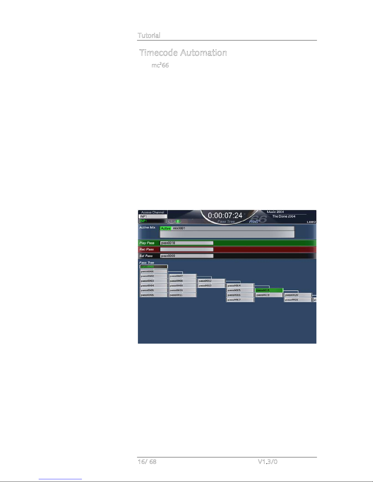
Timecode Automation
The mc266’s automation system provides the ability to automate
console settings referenced to timecode. Note that in addition to
providing automation of channel parameters such as faders,
mutes, aux sends, EQ, etc., the system allows you to automate
other settings such as bus routing, channel signal flow, etc. Also
note that the channels you automate may be any type of
channel – inputs, groups, sums, auxes, VCA masters, GPCs, etc.
Automation data can be written with timecode rolling forwards,
backwards and at any speed, providing fast and efficient mixing.
The way in which data is written is governed by a number of
modes, allowing you to write dynamic or static automation; step
in or step out of write to make updates; protect channels to
prevent overwriting existing moves; and isolate channels to
remove them from the automation system completely.
Each stream of automation data is recorded as a ‘Pass’, and
multiple passes are stored within a ‘Mix’. The ‘Pass Tree’ shows
the history of the mix and enables you to A/B between different
passes:
Multiple mixes may be created for each production and are
stored permanently on the system when you update the
production.

Tutorial
mc²66 V1.3/0 17/ 68
ACCESS CHANNEL/ASSIGN and SCREEN
CONTROL
Located in the centre section of the console are two very
important control areas used throughout the operation of the
console:
•The ACCESS CHANNEL/ASSIGN control panel is used for
a variety of tasks including Central Control Section, bus
and fader strip assignments. In each case, the philosophy
of operation is to place a channel ‘in access’ and then
assign it directly to a destination. This provides fast
configuration of the console without navigating through
screen-based displays.
•The SCREEN CONTROL panel interacts with the centre
control screen and is used for a variety of screen based
tasks. In each case, you ‘focus’ on an area of the display,
and then perform operations from the four soft keys
located above the trackball.
Let’s look at each of these areas in a little more detail.

Tutorial
18/ 68 V1.3/0
The ACCESS CHANNEL/ASSIGN control panel
The ACCESS CHANNEL/ASSIGN control panel is located in the
centre section of the console beneath the BANK and LAYER
switching buttons:
The panel consists of:
•Ten channel type selection buttons – INPUT, MON, AUX,
GPC, GROUP, TRK, SUM, MAIN FADER, STRIP and VCA.
•Two 8-character CHANNEL and LABEL displays.
•The numeric keypad.
•The ASSIGN button – changes the operation of the panel
from access to assign
•The ESC button which can be used to exit any operation.
•Navigation buttons – LEFT, RIGHT, NEXT and PREV.
•The ENTER button – for confirmation.
Note that the ACCESS CHANNEL/ASSIGN panel is
always
active,
and normally, with ASSIGN deselected, selects the channel in
access. Note that the channel in access is always the channel
assigned to the Central Control Section. The name and label are
shown in the CHANNEL and LABEL displays, and in the top left
hand corner of the Central Control Screen throughout all
displays.
Note

Tutorial
mc²66 V1.3/0 19/ 68
There are three ways in which you can modify the channel in
access providing that the LOCK ACC (lock access) button is not
selected:
1. Press the SEL button on a channel or main fader strip.
This is the simplest method for accessing channels on the active
control surface. However, there are times when you will wish to
access channels on an underneath bank or layer of fader strips.
In these cases, you may use either method 2 or 3 as follows:
2. Select the channel type and number using the channel
type selection buttons and numeric keypad:
•Select a channel type by pressing one of the following:
οINPUT – Input channels (up to 384).
οMON – Monitor channels (up to 96).
οAUX – Auxiliary masters (up to 32).
οGPC – General Purpose Channels (up to 256).
οGROUP – Group masters (up to 48).
οTRK – Track busses (up to 96).
οSUM – Sum masters (up to 48).
οVCA – VCA masters (up to 16).
οMAIN FADER – selects the channel type as
assigned to one of the 8 main fader strips.
οSTRIP – selects the channel type as assigned to
one of the channel fader strips.
The channel type button flashes and buttons on the numeric
keypad illuminate; the flashing TYPE NUM message is guiding
you to enter a number.
•Enter the channel number by pressing a number on the
numeric keypad followed by the Enter button. For
example, press 1, 2 and Enter to enter the number twelve.
•Alternatively, enter a three digit number. For example,
pressing 0, 1, and 2 will also enter the number twelve.
Having entered a valid number, the channel type button stops
flashing and the displays update to show the name and label for
the selected channel.
If you try and enter an invalid selection, for example GRP 897,
the CHANNEL display tells you by flashing the letters
NOTAVAIL for ‘Not Available’. Press the ESC button to exit the
operation, and start again.
Note

Tutorial
20/ 68 V1.3/0
3. The third method of changing the channel in access is to
increment or decrement the current channel number:
•Press the NEXT or PREV buttons to increment or
decrement the channel number by DSP type. For
example, to scroll up or down through Input channels 1-
192, Monitor channels 1-96, Groups 1-48, Sums 1-48,
Auxes 1-32, VCA Masters 1-16 and General Purpose
Channels (GPCs) 1-256:
•Alternatively, press the LEFT or RIGHT buttons to assign
the next channel as assigned to the console control
surface. For example, if Input channel 8 is currently in
access and assigned to channel fader strip 8, pressing the
LEFT button selects the DSP channel assigned to fader
strip 7.
The name and label for your selected channel are shown in the
CHANNEL and LABEL displays.
Note that the channel in access may be locked by pressing the
LOCK ACC button:
For example, you may wish to lock INPUT 24 into access so that
it remains accessible from the Central Control Section at all
times during the production.
Remember that updating the channel in access is how you
assign a channel to the Central Control Section. In addition, you
update the channel in access to perform an operation such as
assigning a channel to a fader strip or routing a channel to a
bus.
We’ll cover these operations later in this tutorial, but first let’s
look at screen display navigation.
Note

Tutorial
mc²66 V1.3/0 21/ 68
SCREEN CONTROL
The SCREEN CONTROL panel is located in the centre section of
the console beneath the joystick, and works in conjunction with
the centre control screen and keyboard, located in the console
arm rest or connected to the keyboard USB port, to provide
screen-based control for a variety of functions.
The panel consists of:
•Two rows of display selection buttons – SIGNAL,
MATRIX, BUS, DSP CONFIG, CHAN/CONFIG,
SNAP/SEQUENCE, METER, SYSTEM/STATES and AUTO.
•Rotary control – used for scrolling selections within certain
displays.
•The ESC button.
•The Left/DEC, Right/INC, Up, Down and Enter navigation
buttons.
•Four soft keys, each with its own alphanumeric display.
•The trackball with left and right (blank) select buttons:
One of the displays is
always
active on the central control
screen, and some buttons such as SIGNAL cycle through
multiple pages. For clear feedback of information, there are no
pop-ups or windows – every display stands alone with clearly
defined control areas.
At the top of every display is a title bar containing some
common elements:
•The name and label of the channel in access (e.g. INP1).
•The number of pages available from the SCREEN
CONTROL button, and the current selection – for
example, 1 of 2.
•The local time – for example, 17:28:02 – or timecode.
•The title of the display – for example, Channel.
•The name of the active production – for example,
Formula one 2005 - and the current snapshot if one has
been loaded e.g. Imola.
•If applicable, a red hazard warning flag
Table of contents
Other LAWO Dj Equipment manuals


