LAWO Crystal standard configuration User manual


Copyright
All rights reserved. Permission to reprint or electronically reproduce any document or graphic in whole
or in part for any reason is expressly prohibited, unless prior written consent is obtained fromthe Lawo
AG.
All trademarks and registered trademarks belong to their respective owners. It cannot be guaranteed that
all product names, products, trademarks, requisitions, regulations, guidelines, specifications and norms
are free from trade mark rights of third parties.
All entries in this document have been thoroughly checked; however no guarantee for correctness can
be given. Lawo AG cannot be held responsible for any misleading or incorrect information provided
throughout this manual.
Lawo AGreserves the right to change specifications at any time without notice.
© Lawo AG, 2021

3/149
Table of Contents
crystal standard configuration User Manual Version: 6.4.0/4
Table of Contents
1. Introduction ......................................................................................................................................... 4
2. Important Safety Instructions ................................................................................................................ 5
3. Product Overview ................................................................................................................................ 6
4. The Hardware ..................................................................................................................................... 7
5. Specification ..................................................................................................................................... 13
6. Installation ......................................................................................................................................... 21
7. SystemSetup .................................................................................................................................... 31
8. Operation .......................................................................................................................................... 60
9. The Web UI ..................................................................................................................................... 117
10. Maintenance .................................................................................................................................... 125
11. Appendices ..................................................................................................................................... 134

crystal standard configuration User ManualVersion: 6.4.0/44/149
1. Introduction
1. Introduction
Welcome to crystal standard configuration.
About this Manual
This document describes howto install, configure and operate the system.
Look out for the following which indicate:
Notes - points of clarification.
Tips - useful tips and short cuts.
Attention - alert you when an action should always be observed.
Further Information
Mechanical drawings and data sheets (including weights and dimensions) are available from the Download-
Center (after login).
Lawo User Registration
For access to the Downloads area and to receive regular product updates, please register at:
www.lawo.com/registration.

crystal standard configuration User Manual Version: 6.4.0/4 5/149
2. Important Safety Instructions
2. Important Safety Instructions
Please observe all of the instructions provided in the "General Safety Information for Lawo Equipment" booklet
delivered with your devices. Double-click here to open the information as a pdf.
crystal standard configuration User ManualVersion: 6.4.0/46/149
3. Product Overview
3. Product Overview
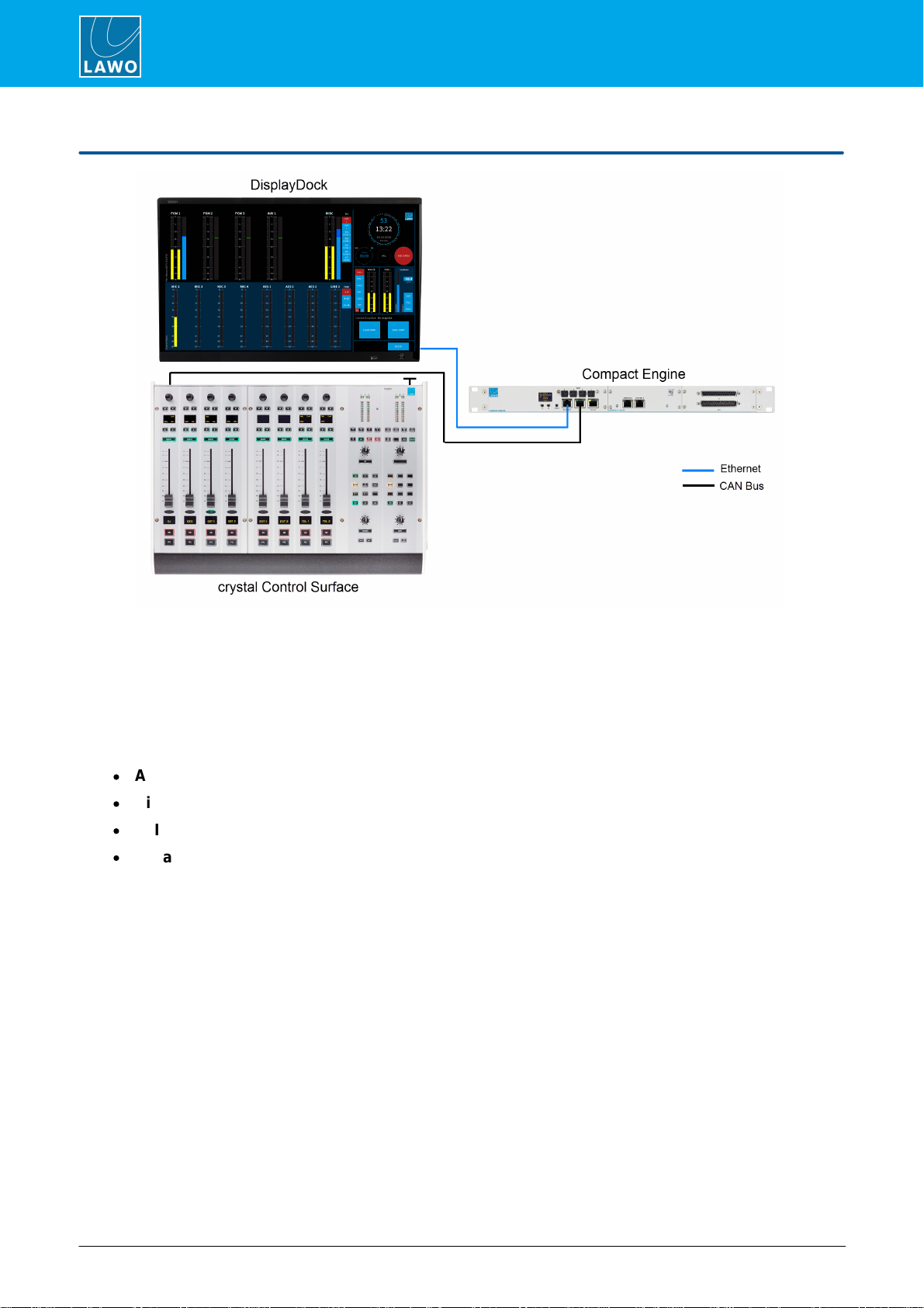
crystal standard configuration is a live mixing console for radio. It consists of three components: Compact
Engine, crystal control surface and DisplayDock. The system is available in two editions: Fader Start or Button
Start.
The control surface comes in a range of frame sizes and connects to the Compact Engine via CAN bus.
DisplayDock runs on a Windows PC connected to the Compact Engine via Ethernet. The host PC must be
provided by the customer. Suitable CAT5 cables are provided for the CANbus and Ethernet connections.
The Compact Engine handles all of the signal processing, system control and IO connections. The IO comprises:
·
Analog IO: 4 Mic/Line in, 4 Line in, 8 Line out, 2 Headphone out.
·
Digital IO: 4 AES3 in/out, 1 x 64-channel MADI (with main and redundant connections).
·
AoIP: 1 x RAVENNA/AES67 interface (configured for 32 stereo Rx/Txstreams).
·
Expansion IO: either 4 AES3 in/out (Fader Start) or 8 Line in/out (Button Start).
All active sources can be mixed to three stereo main outputs: PGM 1 to 3 and two stereo auxes: AUX 1 and 2.
The active sources are the ones assigned to the fader strips, and so the maximum number of mix inputs is
determined by the console frame size.
Any available source can be assigned to any fader strip, allowing you to change the layout of the surface and
mixdifferent inputs. Sources come with a fixed complement of DSP which varies depending on the source type.
For example, all MIC sources provide AutoGain, EQ & Filters, Dynamics (Gate, Expander, Compressor), De-
Esser, AutoMix and Limiter. They also support other functions such as talkback, mix minus creation and
PFL/CUE monitoring. Parameters can be adjusted either fromthe control surface or DisplayDock GUI.
For monitoring, there are two stereo speaker outputs (for the control room and studio), and two stereo
headphone outputs (for the DJ and Guests).Two output meters are always visible: follow MONITOR and PGM 1.
To meter inputs and other outputs you can switch to the "Metering" page.
The master functions on the right of DisplayDock include a system clock, timer, mic open indicator and
telephone call signaling. Other pages include "Source Parameters" (for DSP control) and the "Advanced" page
(with global options and local matrix).
To store and recall settings, the system supports five local memories (stored on the Compact Engine) plus an
unlimited number of DisplayDock snapshots (stored on the control PC).


crystal standard configuration User ManualVersion: 6.4.0/48/149
4. The Hardware
4.1 Console Editions
crystal standard configuration is available in two editions: Fader Start (FS) and Button Start (BT). They differ
in the following ways.
Fader Strip Controls
The two large keys at the bottomof the fader strip provide:
·
Fader Start (FS) - channel ON/off and PFL
·
Button Start (BT) - channel ON and OFF
The soft key MF2b provides:
·
Fader Start (FS) - AMix (auto mixenable).
·
Button Start (BT) - CUE (pre-fade listen).
On a Button Start console, Auto Mix can be enabled from DisplayDock (or the
surface Dynamics controls) when a source is in access. See AutoMix.
Channel On/Off Operation
On Fader Start consoles, the channel "on" state is conditional on the fader position.
On Button Start consoles, the channel "on" state is independent of the fader position.
The behavior is described in more detail later.
PFL / CUE
The pre-fade listen function is named PFL on Fader Start console and CUE on
Button Start consoles. There are also some differences in the default behaviour
(explained later).
Front Expansion IO Slot 2
The right-hand expansion slot at the front of the Compact Engine is fitted with
different IO cards. This provides either more digital or more analog IO:
·
Fader Start (FS) = 1 x AES3 IO Card (4 AES3 in/out)
·
Button Start (BT) = 1 xLINE IO Card (8 Line in/out)
Reference Levels
The editions use different reference levels as follows:
·
Fader Start (FS) = DIN
·
Button Start (BT) = SMPTE

crystal standard configuration User Manual Version: 6.4.0/4 9/149
4. The Hardware
4.2 Control Surface Variants
4-fader single frame
12-fader single frame
crystal can exist as a single or split-frame control surface.
A choice of five main frame layouts are available, with the option to add an extender module to increase the
fader count or create a split-frame surface.
In total, the control surface can include any number of extenders as long as the maximum number of faders
does not exceed 24.
Each frame connects to the Compact Engine via CANbus, and is powered from its own 12V DC power supply
(included). All frames include CAN IN and CAN OUT connectors for easy daisy-chaining. In each case, the
CAN bus address of a module defines its functionality. Thus, frames can be wired in any order.
Split-frame Example
crystal standard configuration User ManualVersion: 6.4.0/410/149
4. The Hardware
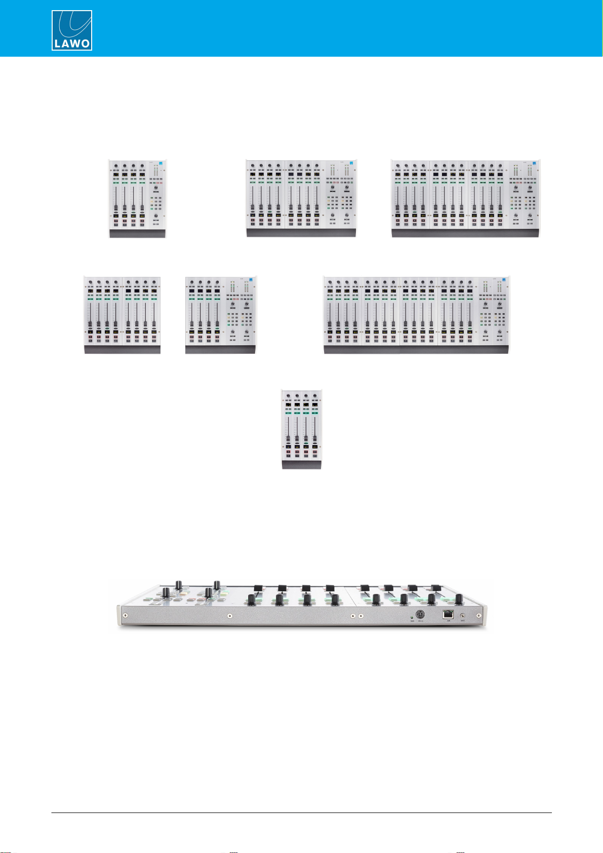
4.2.1 Frame Layouts
Five main frame layouts are available plus the 4-fader extender. Note that the 4-fader main frame supports a
single Central Module, while all other sizes include two.
4-fader
8-fader
12-fader
12-fader split
16-fader
4-fader extender
4.2.2 Placement Options
crystal is designed to be mounted on a table top surface.
All connectors are positioned along the top edge, so you must make sure that these are accessible:
8-fader Surface (top edge)

crystal standard configuration User Manual Version: 6.4.0/4 11/149
4. The Hardware
4.3 The Compact Engine
The 19”/1RU Compact Engine contains the signal processing, control system and routing matrix. It also handles
all audio, control and external Wordclock connections.
4.3.1 Front View
1 Status Display & Menu Control
The front panel display shows local device parameters such as the IP address. You can use the >> and OK
buttons to navigate through the menus.
2 RESET button
Press this button to perform a warm start. The button is recessed to prevent accidental operation.
A warm start will reboot the device. Do NOT perform a warm start while live on air!
3 MADI 1 to 4
MADI ports 1 and 2 are not available for external use. They are used internally to support the RAVENNA card
(7).
MADI ports 3 (and 4) can be used to connect multi-channel digital audio (1 x 64-channels). The two ports provide
main and redundant connections: MADI 3 is the primary port and MADI 4 is the redundant port. The redundant
connection is optional.
4 ETHERNET
The ETHERNET port connects other devices to the Compact Engine control system. In a crystal standard
configuration system, it must connect to the host PC running the DisplayDock software.
5 CAN
The CAN bus port connects to the control surface frame.
6 RS 422
The serial port can be used for debugging, but is usually left unconnected.
7 Expansion Slot 1 - AoIP Streaming
Expansion slot 1 is fitted with a RAVENNA IO Card (952/38) to stream audio to and froman IP network.
By default, 32 stereo streams are transmitted and received via the ETHERNET A port, while ETHERNET B
remains unused. The streams are fully compatible with AES67 and RAVENNA. Optionally, you can re-configure
the two ports to support redundant streaming (via SPS).
In both cases, the streaming network must be properly managed and configured.
8 Expansion Slot 2 - Digital or Analog IO
Expansion slot 2 is fitted with either more digital or more analog IO depending on the console edition:
·
Fader Start: AES3 IO Card (952/32) - 4 x AES3 inputs and 4 xAES3 outputs.
·
Button Start: LINE IO Card (952/31) - 8 xline level inputs and 8 x line level outputs.

crystal standard configuration User ManualVersion: 6.4.0/412/149
4. The Hardware
4.3.2 Rear View
9 Analog & Digital IO
The following audio connections are always included.
·
HEADPHONE 1 & HEADPHONE 2 - two stereo headphone outputs.
·
LINE OUTPUT- 8 x line level outputs.
·
MIC/LINE INPUT - 4 x mic/line in + 4 xline level in.
·
AES3 INPUT - 4 x AES3 inputs.
·
AES3 OUTPUT- 4 x AES3 outputs.
10 GPIO
This connector provides 8 x GPI (optocouplers) and 8 x GPO (silent and self-healing relays) for local signaling
and switched functions.
11 WCLK IN & OUT
WCLK IN can be used to connect an external sync reference. The sync reference options are MADI, WCLK IN,
AES3 or Internal.
WCLK OUT always provides an output of the current system reference.
12 CASE
The CASE grounding screwshould be used to ground the frame.
13 12V DC & AC MAINS Inputs
Every device comes with dual power feeds: AC and DC. To use the DC input, you will need the external 12V DC
power supply. This is optional and must be ordered separately.
If both inputs are connected, then the two feeds provide main and redundant power.
The Compact Engine MUST be connected to the mains using the power cable supplied with the system.


crystal standard configuration User ManualVersion: 6.4.0/414/149
5. Specification
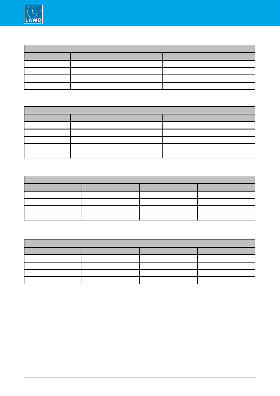
5.1 Available Sources
The tables below describe the available sources.
Note that the AES, LINE and HYBRID sources differ slightly between the Fader Start and Button Start editions.
All Editions
Source Name
Format
Physical Input
DSP Resources
Connector
Input No. / StreamName
EQ
Dyn
Lim
DE/AMx
MIC 1 ...4
mono
MIC/LINE INPUT
Input 1 ...4
ü
ü
ü
ü
LINE 1
stereo
"
Inputs 5&6
ü
ü
ü
û
EXT
stereo
"
Inputs 7&8
û
û
û
û
RAVCO1 & 2
stereo
ETHERNET A
RAVCodec 1 & 2
ü
ü
ü
û
RAVCO3 & 4
stereo
"
RAVCodec 3 & 4
û
û
û
û
RAV 01 ...03
stereo
"
RAVIn 1 ...3
ü
ü
ü
û
RAV 04 ...28
stereo
"
RAVIn 4 ...28
û
û
û
û
MADI 01...
MADI 32
stereo
MADIports 3 (& 4)
MADIchannels 1&2...
MADIchannels 63&64
û
û
û
û
Fader Start (FS)
Source Name
Format
Physical Input
DSP Resources
Connector
Input No. / StreamName
EQ
Dyn
Lim
DE/AMx
AES 1 ...2
stereo
AES3 INPUT (rear)
Inputs 1&2 ...3&4
ü
ü
ü
û
AES 3
stereo
"
Inputs 5&6
û
û
û
û
AES CO
stereo
"
Inputs 7&8
ü
ü
ü
û
AES 4 ...6
stereo
AES3 INPUT (front)
Inputs 1&2 ...5&6
û
û
û
û
HYB 1 ...2
mono
"
Input 7 ...8
ü
ü
ü
û
Button Start (BT)
Source Name
Format
Physical Input
DSP Resources
Connector
Input No. / StreamName
EQ
Dyn
Lim
DE/AMx
AES 1
stereo
AES3 INPUT (rear)
Inputs 1&2
ü
ü
ü
û
AES 2 ...3
stereo
"
Inputs 3&4 ...5&6
û
û
û
û
AES CO
stereo
"
Inputs 7&8
ü
ü
ü
û
LINE 2
mono
LINE INPUT (front)
Inputs 1&2
ü
ü
ü
û
LINE 3 ...4
mono
"
Inputs 3&4 ...5&6
û
û
û
û
HYB 1 ...2
mono
"
Input 7 ...8
ü
ü
ü
û

crystal standard configuration User Manual Version: 6.4.0/4 15/149
5. Specification
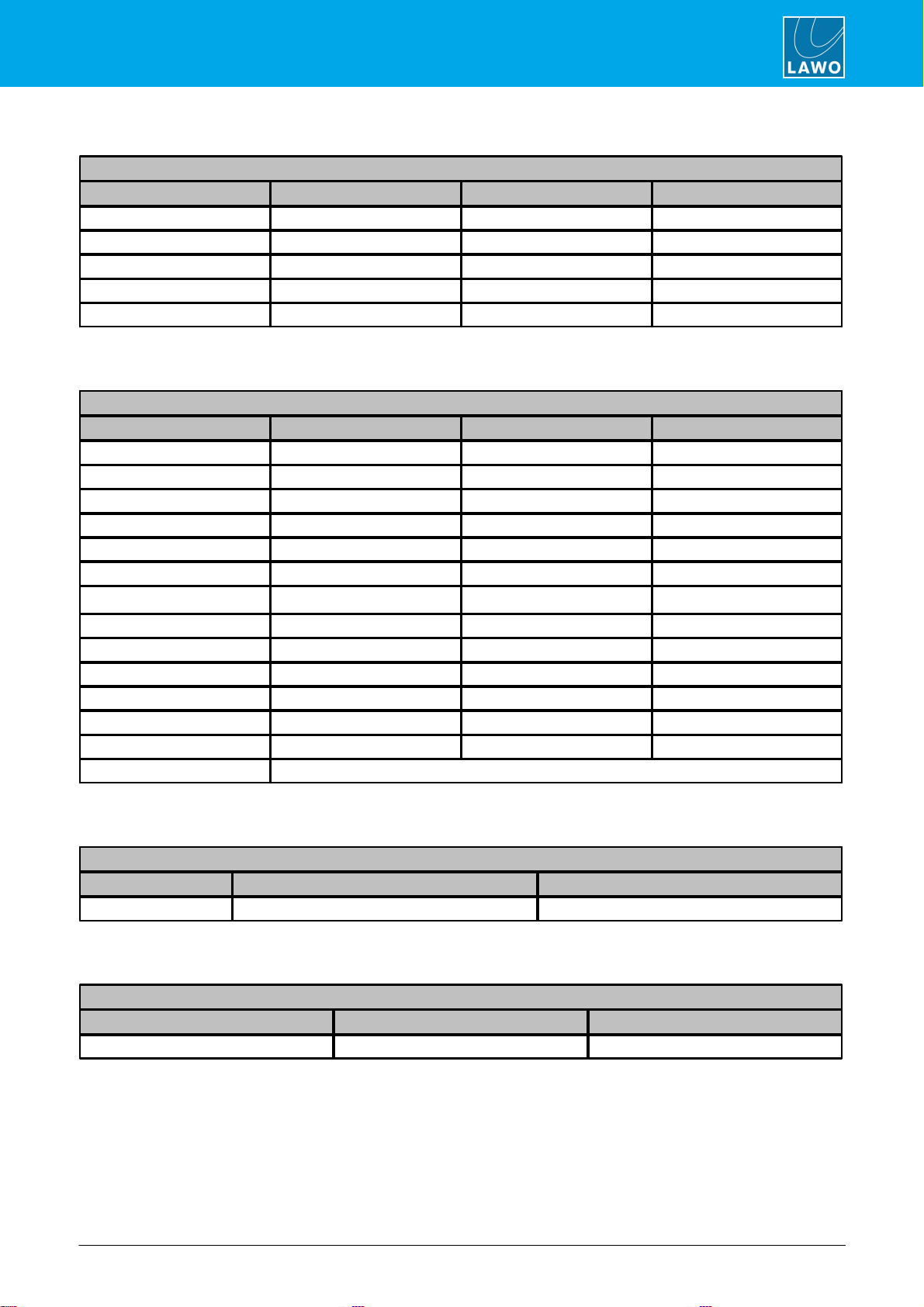
5.2 Available Buses
The tables below describes the available summing and N-1 buses.
Note that the pre-fade listen bus is called PFL on Fader Start consoles and CUE on Button Start consoles.
Summing Bus Name
Format
Pickup Point
Outputs
PGM 1
stereo
post-fader
see Default Audio.
PGM 2
stereo
"
"
PGM 3
stereo
"
"
AUX 1
stereo
pre or post-fader
"
AUX 2
stereo
"
"
PFL / CUE
stereo
pre-fader
PFL/CUE appears on the MONCR and
MON DJ outputs.
N-1 Bus Name
Format
Pickup Point
Outputs
HYB 1
mono
post-fader N-1 (mix minus)
see Default Audio.
HYB 2
mono
"
"
RAV CODEC 1
mono
"
"
RAV CODEC 2
mono
"
"
RAV CODEC 3
mono
"
"
RAV CODEC 4
mono
"
"
AES CODEC
mono
"
"
crystal standard configuration User ManualVersion: 6.4.0/416/149
5. Specification
5.3 Default Audio Assignments
The tables which followlist the default audio assignments for the inputs and outputs.
For the inputs, the source assignments are fixed and cannot be changed by the user. Instead, you can choose
which inputs are active in the mixby changing the fader strip assignments on the surface.
For the outputs, the configuration loads the default audio assignments. These can be modified from the local
matrix(in DisplayDock).
5.3.1 Analog Inputs
MIC/LINE INPUT (Compact Engine rear panel)
Input Number
Source Name
Format
1
MIC 1
mono
2
MIC 2
mono
3
MIC 3
mono
4
MIC 4
mono
5/6
LINE 1
left/right
7/8
EXT
left/right
Button Start Consoles only
LINE INPUT (Compact Engine front expansion slot 2)
Input Number
Source Name
Format
1/2
LINE 2
left/right
3/4
LINE 3
left/right
5/6
LINE 4
left/right
7
HYB 1
mono
8
HYB 2
mono
crystal standard configuration User Manual Version: 6.4.0/4 17/149
5. Specification
5.3.2 Analog Outputs
LINE OUTPUT (Compact Engine rear panel)
Output Number
Local Matrix Name
Format
Default Audio from
1/2
LINE 1
left/right
PGM1
3/4
LINE 2
left/right
HYB1 / HYB2
5/6
LINE 3
left/right
MON STUDIO
7/8
LINE 4
left/right
MON CR
HEADPHONE SOCKETS (Compact Engine rear panel)
Output Number
Local Matrix Name
Format
Default Audio from
HEADPHONE 1
HP 1
left/right
MON DJ
HEADPHONE 2
HP 2
left/right
MON GUEST
Button Start Consoles only
LINE OUTPUT (Compact Engine front expansion slot 2)
Output Number
Local Matrix Name
Format
Default Audio from
1/2
LINE 5
left/right
AUX1
3/4
LINE 6
left/right
AUX2
5/6
LINE 7
left/right
-
7/8
LINE 8
left/right
-
crystal standard configuration User ManualVersion: 6.4.0/418/149
5. Specification
5.3.3 Digital Inputs
AES3 INPUT (Compact Engine rear panel)
Input Number
Source Name
Format
1/2
AES 1
left/right
3/4
AES 2
left/right
5/6
AES 3
left/right
7/8
AES CODEC
left/right
Fader Start Consoles only
AES3 INPUT (Compact Engine front expansion slot 2)
Input Number
Source Name
Format
1/2
AES 4
left/right
3/4
AES 5
left/right
5/6
AES 6
left/right
7
HYB 1
mono
8
HYB 2
mono
5.3.4 Digital Outputs
AES3 OUTPUT (Compact Engine rear panel)
Output Number
Local Matrix Name
Format
Default Audio from
1/2
AES 1
left/right
PGM1
3/4
AES 2
left/right
PGM2
5/6
AES 3
left/right
PGM3
7/8
AES 4
left/right
AES CODEC
Fader Start Consoles only
AES3 OUTPUT (Compact Engine front expansion slot 2)
Output Number
Local Matrix Name
Format
Default Audio from
1/2
AES 5
left/right
AUX1
3/4
AES 6
left/right
AUX2
5/6
AES 7
left/right
-
7/8
AES 8
left/right
-
crystal standard configuration User Manual Version: 6.4.0/4 19/149
5. Specification
5.3.5 RAVENNA Inputs
ETHERNET A(streaming port ra0)
RAVENNAInput Number
Rx StreamName
Source Name
Format
1/2
RAVCodec 1
R COD1
left/right
3/4
RAVCodec 2
R COD2
left/right
5/6
RAVCodec 3
R COD3
left/right
7/8
RAVCodec 4
R COD4
left/right
9/10... 63/64
RAVIn 1... RAV In 28
RAV1... RAV 28
left/right
5.3.6 RAVENNA Outputs
ETHERNET A(streaming port ra0)
RAVENNAOutput Number
Tx StreamName
Format
Default Audio from
1/2
RAVPGM1
left/right
PGM1
3/4
RAVPGM2
left/right
PGM2
5/6
RAVPGM3
left/right
PGM3
7/8
RAVPGM4
left/right
AUX1
9/10
RAVAUX1
left/right
AUX2
11
RAVCODEC 1
mono
RAVCODEC N-1
12
RAVCODEC TB
mono
RAVCODEC TB
13
RAVCODEC 2
mono
RAVCODEC N-1
14
RAVCODEC 2 TB
mono
RAVCODEC TB
15
RAVCODEC 3
mono
RAVCODEC N-1
16
RAVCODEC 3 TB
mono
RAVCODEC TB
17
RAVCODEC 4
mono
RAVCODEC N-1
18
RAVCODEC 4 TB
mono
RAVCODEC TB
19... 64
additional Tx streams must be created using the RAVENNA Web UI.
5.3.7 MADI Inputs
MADI 3 & 4 (Compact Engine front panel)
Channel Number
Source Name
Format
1/2... 63/64
MADI1... MADI32
left/right
5.3.8 MADI Outputs
MADI 3 & 4 (Compact Engine front panel)
Channel Number
Format
Default Audio from
1/2... 63/64
left/right
crystal standard configuration User ManualVersion: 6.4.0/420/149
5. Specification
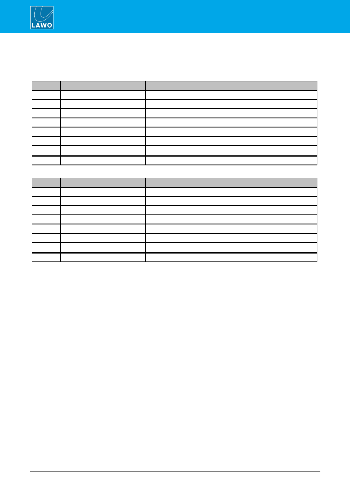
5.4 GPIO Functions
The tables below describe the functionality provided by the GPIO connector.
8 xGPI (opto-couplers) and 8 x GPO (silent CMOS relays) are supported.
GPI
Function Name
Logic
1
MIC 2 ON / OFF / COUGH
ON / OFF toggle; if ON and "push and hold" (400 ms) > mute
2
MIC 3 ON / OFF / COUGH
ON / OFF toggle; if ON and "push and hold" (400 ms) > mute
3
MIC 4 ON / OFF / COUGH
ON / OFF toggle; if ON and "push and hold" (400 ms) > mute
4
MIC 2 TALK
INPUT MUTE MIC; > DJ HP and CR
5
MIC 3 TALK
INPUT MUTE MIC; > DJ HP and CR
6
MIC 4 TALK
INPUT MUTE MIC; > DJ HP and CR
7
INCOMING CALL HYB 1
HYBRID 1 (LOCAL)
8
INCOMING CALL HYB 2
HYBRID 2 (LOCAL)
GPO
Function Name
Logic
1
REDLIGHT CR
2
REDLIGHT STUDIO
3
FADER START LINE 1
4
FADER START AES 1
5
HYBRID 1 ON
HYBRID 1 (LOCAL)
6
HYBRID 2 ON
HYBRID 2 (LOCAL)
7
PGM1 SILENCE
8
MIC 1 "ON" TALLY
Table of contents
Other LAWO Dj Equipment manuals


