LBC LCR7W Guide

2
READ FIRST T
THIS MANUAL MUST BE RETAINED FOR FUTURE REFERENCE. READ, UNDERSTAND AND FOLLOW
THE INSTRUCTIONS AND WARNINGS CONTAINED IN THIS MANUAL.
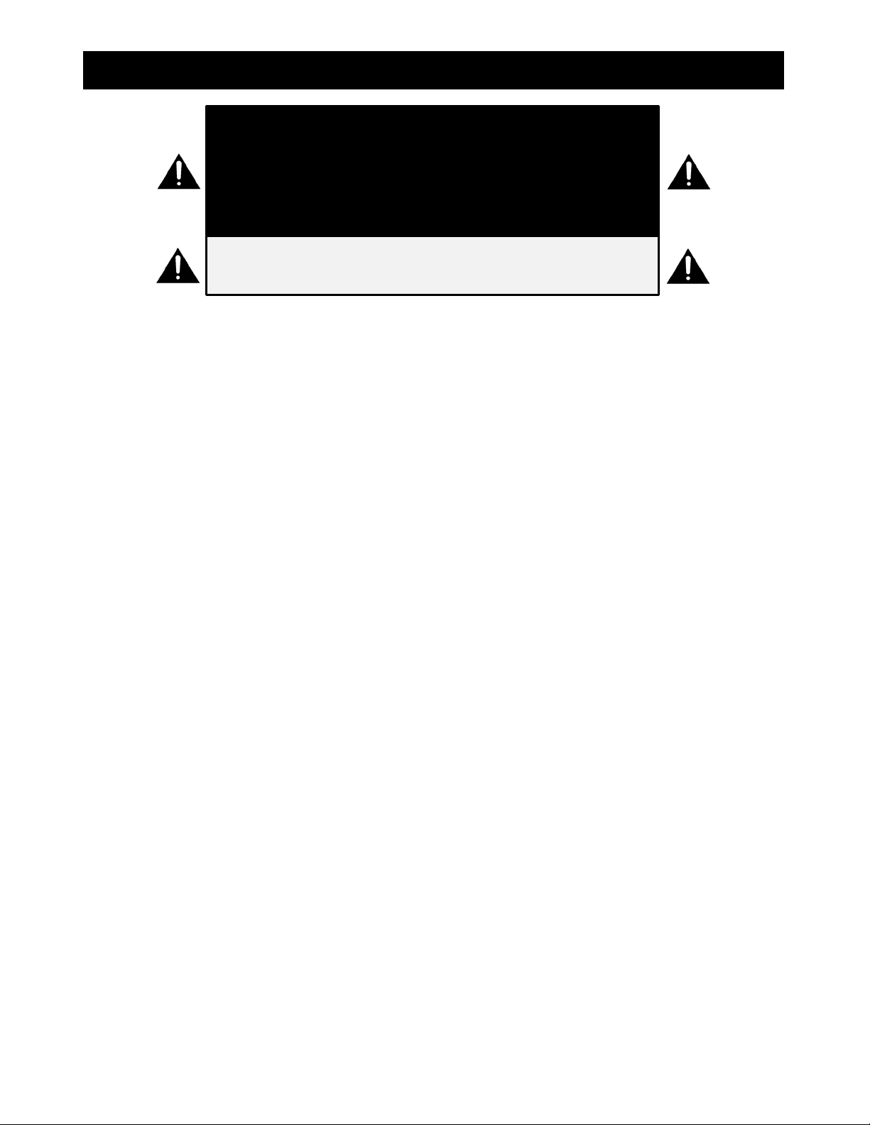
W A R N I N G
DO NOT STORE OR USE GASOLINE
OR OTHER FLAMMABLE VAPORS
AND LIQUIDS IN THE VICINITY OF
THIS OR ANY OTHER APPLIANCE.
D A N G E R
W A R N I N G
IMPROPER INSTALLATION,
ADJUSTMENT, SERVICE OR
MAINTENANCE CAN CAUSE
PROPERTY DAMAGE, INJURY OR
DEATH. READ THE INSTALLATION,
OPERATING AND MAINTENANCE
INSTRUCTIONS THOROUGHLY
BEFORE INSTALLING OR SERVICING
THIS EQUIPMENT.
C A U T I O N ALWAYS KEEP THE AREA NEAR
THE APPLIANCE FREE FROM
COMBUSTIBLE MATERIALS.
This LBC Rotisserie was manufactured to rigid standards. The appliance has been tested and is listed by Intertek Testing
Services (ETL Semko) and meets applicable safety and sanitation standards.
A) The responsibility of the manufacturer is to supply suitable, comprehensive instructions and recommendations for
proper operation and maintenance.
B) All operations, maintenance and repair of this or any LBC Bakery Equipment appliance must be performed by
properly trained and qualified personnel, and all such operations, maintenance and repair must be performed in a
diligent manner. It is the responsibility of the owner/operator to ensure proper training and diligence of any person
coming into contact with either the subject units or the output (product, fumes or otherwise) of the subject units.
It is the responsibility of the owner/operator to ensure that the subject units are installed and operated in
accordance with OSHA Standard 1910.263.
C) A regular periodic program of cleaning, inspection and maintenance must be established and comprehensive
maintenance records maintained. It is the sole responsibility of the owner/operator to establish, schedule and
enforce the frequency and scope of these programs in keeping with recommended practice and with due
consideration given to actual operating conditions.
D) The appliance must be operated within limits which will not exceed its working limits. It is the responsibility of the
user to operate this appliance in accordance with the rules and limits described in this manual and the published
product specification sheet, and in accordance with the directions and instructions of the owner/operator of the
appliance or employer, and in accordance with applicable federal, state and local laws and ordinances.

3
TABLE of CONTENTS T
Read First . . . . . . . . . . . . . . . . . . . . . . . . . . . . . . . . . . . . . . . . . . . . . . . . . . . . . . . . . . . . . . . . . . . . . 2
Specifications . . . . . . . . . . . . . . . . . . . . . . . . . . . . . . . . . . . . . . . . . . . . . . . . . . . . . . . . . . . . . . . . . 4
Configurations . . . . . . . . . . . . . . . . . . . . . . . . . . . . . . . . . . . . . . . . . . . . . . . . . . . . . . . . . . . . . . . . . 5
Conditions of Installation . . . . . . . . . . . . . . . . . . . . . . . . . . . . . . . . . . . . . . . . . . . . . . . . . . . . . . . . . 6
Receiving and Unpacking . . . . . . . . . . . . . . . . . . . . . . . . . . . . . . . . . . . . . . . . . . . . . . . . . . . . . . . . . 7
Installation . . . . . . . . . . . . . . . . . . . . . . . . . . . . . . . . . . . . . . . . . . . . . . . . . . . . . . . . . . . . . . . . . . . . . 8
Controller Operation . . . . . . . . . . . . . . . . . . . . . . . . . . . . . . . . . . . . . . . . . . . . . . . . . . . . . . . . . . . . 13
Parts List . . . . . . . . . . . . . . . . . . . . . . . . . . . . . . . . . . . . . . . . . . . . . . . . . . . . . . . . . . . . . . . . . . . . . . 14
Notes . . . . . . . . . . . . . . . . . . . . . . . . . . . . . . . . . . . . . . . . . . . . . . . . . . . . . . . . . . . . . . . . . . . . . . . . . 19
Wiring Diagram . . . . . . . . . . . . . . . . . . . . . . . . . . . . . . . . . . . . . . . . . . . . . . . . . . . . . . . . . . . . . . . . . 20
Warranty . . . . . . . . . . . . . . . . . . . . . . . . . . . . . . . . . . . . . . . . . . . . . . . . . . . . . . . . . . . . . . . . . . . . . . 22

4
SPECIFICATIONS T
3
32.1"
[815mm]
Stand
39.9" [1013mm]
39.4"
[1001mm]
30.8"
[782mm]
31.9"
[810mm]
Single
Door
(Standard)
Double
Door
(Option)
26.3"
[688mm]
1
1
2
4
1
2
5.0" [127mm]
6.0"
[152mm]
1
3
2
2.4" [61mm]
Optional
Electrical
Connection
Locations
Water Inlet (3/4” hose)
(120 – 140
o
F, 1/2 GPM at
25 - 50 psi required)
Water Drain (1" Barb)
Electrical (See Table Below)
Utility Connection Key:
7.3" [185mm]
4
1.9" [48mm]
3
7.6"
[192mm]
4Grease Drain (1" Barb)
3
7.0"
[178mm]
Leg
32.6"
[828mm]
Voltage kW Min Circuit Ampacity Max Breaker Size Shipping
Weight
Freight
Class
1 Phase
3 Phase
1 Phase
3 Phase
208 VAC 8.0 55 N/A 60 N/A
660 lbs
[299 kg] 85
240 VAC 8.0 50 N/A 60 N/A
208 VAC 9.0 N/A 40 N/A 60
240 VAC 9.0 N/A 35 N/A 60

5
CONFIGURATIONS S
LCR7W Rotisserie
Countertop or
Floor Mount
Stand Mount
6.0” Legs
LCR7W Rotisserie
LST7 Stand

6
CONDITIONS of INSTALLATION I
LBC Bakery Equipment shall, for a fee contingent on site location and provided that the conditions of installation are
met, provide a factory-authorized service agency to install the LBC Rotisserie. The job site must be ready for the
installation before LBC Bakery Equipment or its authorized agent arrives. If the installation site is not properly prepared
or if there are construction delays, the customer shall be responsible for all expenses incurred during this delay. All
expenses resulting from job delay or extension, for reasons beyond the control of LBC Bakery Equipment, shall be the
responsibility of the customer. Installation shall be conducted during normal business hours. This installation is for a
single trip. Start-up and training are not included.
IN ALL CASES, THE ELECTRICAL, WATER AND DRAIN CONNECTIONS AND VENTILATION MUST MEET ALL FEDERAL,
STATE AND LOCAL CODES OR ORDINANCES.
It is the responsibility of the owner/operator to do the following:
A. Secure all required permits and meet all local code requirements.
B. Ensure the installation site is cleared and ready for installation before the authorized installer arrives on site. The
site shall be smooth and level.
C. Provide electrical utilities within five (5) feet of the installation location per the specifications provided by LBC
Bakery Equipment
D. Provide licensed trades person to make the final electrical and water connections.
E. Provide adequate ventilation, including vented hoods and associated roof penetrations.
F. Remove all packing materials, crates, etc. resulting from the installation.
G. Provide any sheet metal work required by local codes or otherwise to bridge gaps between appliance and adjacent
walls or other building structures.

7
RECEIVING and UNPACKINGI
C A U T I O N
SHIPPING STRAPS ARE UNDER TENSION AND CAN
SNAP BACK WHEN CUT.
W A R N I N G
THE ROTISSERIE WEIGHS UP TO 600 LBS. FOR
SAFE HANDLING, INSTALLER SHOULD OBTAIN
HELP AS NEEDED OR EMPLOY APPROPRIATE
MATERIAL-HANDLING EQUIPMENT (SUCH AS A
FORKLIFT, DOLLY OR PALLET JACK) TO REMOVE
THE UNIT FROM ITS PACKING MATERIALS AND
TO MOVE IT TO THE PLACE OF INSTALLATION.
Receiving
Upon receiving the appliance, immediately check for damage (both visible and concealed) and loss. Visible damage must
be noted on the freight bill at the time of delivery and signed by the carrier’s agent. Concealed damage or loss means
damage or loss which does not become apparent until the merchandise has been unpacked. If concealed damage or loss
is discovered upon unpacking, make a written request for inspection by the carrier’s agent within 15 days of delivery.
All packing material should be kept for the inspection. DO NOT return damaged merchandise to LBC Bakery Equipment;
you must file your claim with carrier.
Location
Prior to unpacking, move the appliance as near to its intended location as practical. Existing packaging will help protect
the oven from physical damage normally associated with moving it through hallways and doorways.
Unpacking
The appliance will arrive inside a carton or wood crate affixed to a pallet. Remove the outside packaging and strapping
bands before lifting the unit from the pallet and placing in its intended location.

8
INSTALLATION (Part 1 of 5)0
C A U T I O N
THIS APPLIANCE WEIGHS UP TO 600 LBS. FOR SAFE
HANDLING, INSTALLER SHOULD OBTAIN HELP AS
NEEDED OR EMPLOY APPROPRIATE MATERIAL-
HANDLING EQUIPMENT (SUCH AS A FORKLIFT, DOLLY
OR PALLET JACK) TO REMOVE THE UNIT FROM ITS
PACKING MATERIALS AND TO MOVE IT TO THE PLACE
OF INSTALLATION.
C A U T I O N
ANY STAND, COUNTER OR OTHER DEVICE ON WHICH
THIS APPLIANCE WILL BE LOCATED MUST BE DESIGNED
TO SUPPORT ITS WEIGHT
INSTALLATION OF THIS APPLIANCE MUST BE DONE
BY PERSONNEL QUALIFIED TO WORK WITH
ELECTRICITY. IMPROPER INSTALLATION CAN CAUSE
INJURY TO PERSONNEL AND/OR DAMAGE TO
EQUIPMENT.
W A R N I N G
C A U T I O N
ALL ELECTRICAL, MECHANICAL, GAS, VENTILATION
AND EXHAUST CONNECTIONS MUST MEET ALL
FEDERAL, STATE AND LOCAL CODES OR ORDINANCES.
N O T I C E
During the first few hours of operation, you may notice a
small amount of smoke and/or a faint odor coming from
the appliance. This is normal in a new equipment and
will disappear after a few hours of use.
Clearances
Minimum clearance from combustible construction: 0” from sides, 1” from back (single-door ovens only) or 6” from back
(double-door ovens) and 6” from top. This appliance may be installed on combustible surfaces. The installation location
must allow adequate clearances for servicing and for proper operation of loading door(s).
Stand
If the oven is supplied with a stand, check the level of the top surfaces. If the stand is not level, add shims (washers are
provided with the oven). Secure the oven to the stand with stainless steel hardware provided (16 each of the following:
10mm-1.2 x 20mm hex bolts, 10mm lock washers and 10mm plain washers.)
Drip Plates
Unpack and install the drip plates. No mounting hardware is required. The plates rest on the support pins located on each
side wall.

9
INSTALLATION (Part 2 of 5))
Interim Inspection
Verify/Perform the following:
1. Ensure loading door(s) open/close freely past 90owithout obstruction.
2. Remove all packing materials from inside oven.
3. Remove carousel wheel shipping ties at carousel support hub (left wall) and drive arm (right wall).
4. Remove clear protective plastic covering from data plate and 15A fuse “Caution” plate.
Water Drain Connection
Locate the 1” hose barb fittings on the valve underneath the oven. (NOTE: There are two fittings; the water fitting is on
the right as you face the backside of the oven.) Connect a 1” diameter PVC hose to the water fitting and secure with the
band clamp provided. Route the hose to an air-gap floor drain.
Water
Drain
Oven Body
(Rear View)
Grease Drain Connection
Locate the 1” hose barb fittings on the valve underneath the oven. (NOTE: There are two fittings; the grease drain fitting
is on the left as you face the backside of the oven.) Connect a 1” diameter PVC hose to the grease fitting and secure with
the band clamp provided. Route the hose to a grease receptacle.
Oven Body
(Rear View)
Grease
Drain

10
INSTALLATION (Part 3 of 5))
Soap Supply Connection
Connect the soap bottle to the soap inlet. All parts necessary to complete this step are included with the oven. Locate the
tube connector (1/2” NPTM x 1/4” hose barb) and connect it to the oven soap inlet. Secure the tube with a band clamp.
Attach the other end of the tube to the soap bottle cap and secure it with a band clamp.
Oven Body
(Right Side View)
Soap Tube
(included with oven)
Tube Connector
(included with oven)
Bottle Cap
Soap
Band Clamps
(included with oven)
Soap Inlet
NOTE: For low-soap alert to function
properly, the hose must be installed with no
dips or flat lengths. It is strongly
recommended to locate the soap bottle
directly under the oven and route the hose as
vertically as possible.
Flow
Water Supply Connection
Refer to water requirements (volume, pressure, temp, pipe size) outlined in Specifications section. Connect the water
supply to the 3/4” hose fitting located at the water inlet. A flexible water line is recommended if the oven is installed with
a stand. If using a flexible water line, provide sufficient length to allow the oven to be moved for cleaning without applying
tension to the connections.
Water Inlet
Water Supply
Flow
Oven Body
(Right Side View)

11
INSTALLATION (Part 4 of 5))
Electrical Connection
Power can be connected from the top or bottom of the oven at the existing knockout holes in the ceiling or the floor of the
control compartment.A flexible conduit or cord is recommended if the oven is installed with a stand. If using flexible
conduit, provide sufficient length to allow the oven to be moved for cleaning without applying tension to the connections.
Functional Check (also refer to Controller Operation section)
Turn the oven on, rotate the valve handle to Cook and verify:
1. Oven automatically pre-heats to the temp programmed in an open recipe.
2. Carousel wheel rotates.
3. Interior lights are off.
4. Interior fans and the control-area cooling fans are on.
While the oven is preheating, open the loading door and verify:
5. The word “door” flashes in the timer display.(NOTE: For ovens with two doors, check each door independently).
6. Heat is off (elements are de-energized).
7. Carousel wheel stops rotation.
8. Interior light(s) are on.
9. Press the yellow pushbutton on the jamb and ensure the carousel wheel rotates.Release pushbutton and ensure
the carousel wheel stops.
While the oven is preheating, close the loading door, press the Timer Start/Stop button and verify:
10. Interior lights turn on when the Timer begins counting.
Rotate the valve handle to Wash and verify:
11. Interior lights are off.
12. Pump energizes and soap is drawn from the soap bottle.
13. “Saun - dEtErgEnt” message does not appear and buzzer is silent when pump runs with soap hose immersed in
liquid.
14. “Saun - dEtErgEnt” message appears and buzzer sounds when pump runs and soap hose is not immersed in liquid.
Ensure hose is completely empty of liquid to perform this step.
15. Oven cools or heats to 150oF.
16. Water valve opens, spraying the soap/water mix into oven through spray arm.
17. Spray arm spins freely when the water valve opens.
18. At the end of the wash cycle, the oven automatically shuts off.
Chain Restraint Kit (Optional)
Units on stands must be secured to a building structure with a chain restraint. Affix one end of the restraint to the side
panel of oven (the non-control side is recommended) at any existing panel mount screw. An additional hole must be
drilled next to the existing mount screw to affix the 2-hole plate located on either end of the restraint. A drill bit and
mounting hardware are provided in the chain restraint kit. Attach the loose end of the restraint to a secure structure and
affix the warning label provided (“WARNING – ATTENCION: RISK OF ELECTRIC SHOCK …”) to the control-side panel.
Set Temperature Scale
Simultaneously press-and-hold both set point arrows for 3 seconds to change the temp scale from oF to oC and back.
Once set, the selected scale will remain active unless re-set otherwise.
Controller Calibration
Insert a thermocouple inside the cook chamber at the center of any oblong hole in the ceiling fan cover. Route the probe
wire out of the loading door opening and adjust the oven set point to 350oF. Allow the oven to reach set point

12
INSTALLATION (Part 5 of 5))
and stabilize for at least 90 minutes. If the thermocouple reading and the controller actual temp differ by more than a
couple degrees, the control must be calibrated. To begin, make a note of the temp difference between the thermocouple
and controller actual temp, then turn control power button off and simultaneously press-and-hold the set temp up/down
arrows for 3 seconds until a value appears in set point display. Use set point up or down arrow to add or subtract difference
in temp. (EXAMPLE: If thermocouple is 10ohigher than actual temp, add 10. If thermocouple is 10olower than actual temp,
subtract 10.) Turn control button on and re-check thermocouple against controller actual temp. Repeat this procedure
until both temps match.
Final Inspection
Verify the following:
1. All screws are tight
2. All electrical connections are tight
3. All plumbing connections are tight and do not leak
4. Fingerprints, dirt and sticker residue have been cleaned from oven

13
CONTROLLER OPERATION .
Silence Alarm
Button
Quick-Select Recipe Buttons
Recipe Save Button
After creating a recipe,
press this button twice
to save it
Back+3 Button
Press to go back one event
and add 3 minutes. Each
additional press adds another
3 minutes.
Timer Start/Stop/Reset Button
Press to start/stop Timer;
press-and-
hold for 3 seconds
to reset Timer
Change Temperature Scale
Simultaneously press-and-hold
up and down arrows for 3
seconds to change scale from
oF to oC and back
Actual Temp
Display
Set Point
Display
Time Display
Cook Event Buttons
Use these when
creating a recipe; up
to 3 events may be
programmed
(NOTE: To ignore Sear
and/or Roast events,
enter a time of 0:00
for that event)
Wash Button
1X = Normal Wash;
2X = Heavy Wash.
Press to change
from 1X to 2X
and back again.

14
PARTS LIST (Part 1 of 5)W
N O T I C E
Service on this or any other LBC appliance must
be performed by qualified personnel. For an
approved service representative in your area,
visit our website at www.lbcbakery.com or call
our factory toll free at 1-888-722-5686.
C A U T I O N
USE OF ANY REPLACEMENT PARTS OTHER THAN
THOSE SUPPLIED BY LBC OR THEIR AUTHORIZED
DISTRIBUTORS CAN CAUSE BODILY INJURY TO
THE OPERATOR AND/OR DAMAGE TO THE
APPLIANCE AND WILL VOID ALL WARRANTIES.
BOTH HIGH AND LOW VOLTAGES ARE
PRESENT INSIDE OF THIS APPLIANCE WHEN
THE UNIT IS PLUGGED/WIRED INTO A LIVE
RECEPTACLE. BEFORE REPLACING ANY PARTS,
DISCONNECT THE UNIT FROM THE ELECTRIC
POWER SUPPLY.
W A R N I N G

15
PARTS LIST (Part 2 of 5)W

16
PARTS LIST (Part 3 of 5)W

17
PARTS LIST (Part 4 of 5)W
Item No. Part Description Quantity Part No. Comments
1 Controller 1
40102-75
WDRs without
valve switches
40102-75-F
WDRs with
valve switches
2
15A Fuse
2
30900-01
3
Fuse Holder
2
30901-02
4
Axial Fan
2
30200-46
5
Fan Guard
2
50201-11
6 Handle, Loading Door 1 or 2
180-781-2
Tubular handle
50800-96
Latching handle
7
Spray Arm
1
180-794-1
8
Cover, Reservoir
1 or 2
180-783-1
9 Loading Door, Outer 1 or 2
180-744-4
WDRs with “e”
profile door gasket
180-744-5
WDRs with flat
sheet door gaskets
10 Loading Door, Inner 1 or 2
180-743-1
WDRs with “e”
profile door gasket
180-837-1
WDRs with flat
sheet door gaskets
11
Drip Plate
2
- - -
Call factory
20
Element, Heating (2kW)
0 or 1
11090-40
Single phase only
Element, Heating (3kW)
2 or 3
11090-39
21
Capacitor, Fan (2.2μF)
2
40704-11
22
Thermocouple Temperature Sensor
1
41100-42
23
Relay
4
30701-05
24
Alarm
1
30802-07-1
25
Contactor
1
30700-17
26
Transformer
1
31400-26
27
Power Distribution Block
1
30500-07
28
High Limit Cutout
1
30401-33
29
Gearbox (90 Degrees, 1:90 Ratio)
1
30200-50
30
Gearbox (1:10 Ratio)
1
30200-49
31
Motor
1
30200-51
32
Capacitor, Motor (4.0µF)
1
40704-10
40
Thermal Snap Disc (Relay Protection)
1
30301-05
41
Fan, Ceiling
2
71500-32
42
Fan Blade, Ceiling
2
180-205-1
50 Door Switch Assembly 1 or 2 180-767-2
One switch per
loading door
51
Thermal Snap Disc (Lights)
1 or 2
30301-06
54
Lamp Holder
2 or 4
31602-21
55
Lamp, 200W
1 or 2
31603-88
55a
Interior Light Cover
1 or 2
180-774-2
56
Switch, Pressure
1
30308-07-B
Low soap detection
57
Pump, Peristaltic
1
70403-07
58
Valve, Solenoid - Water
1
70403-08

18
PARTS LIST (Part 5 of 5)W
64 Carousel Assembly, Stainless Steel 1 180-816
See item 94 for
non-stick carousel
assembly
65
Timer
1
30701-07
66
Relay, Brake
1
30701-05-240
67 Water / Grease Valve Switch 2
30301-15
Roller switch
30308-20
Magnetic switch
70
Solenoid, Brake
1
70403-04-1-240
Optional Parts and Accessories
Item No. Part Description Quantity Part No. Comments
90
Stand with Casters
1
LST7
91
Mobile Skewer Rack
1
MSR7
92
Caster (Swivel with Brake)
4
72901-33
93
6” Adjustable Leg
4
72901-34
94
Carousel Assembly, Non-Stick Coating
1
180-816-C
95 Angle Spit 7
LCR7-SV
Stainless steel
LCR7-SV-C
Non-stick coating
96 Fork Spit 7
LCR5-SF
Stainless steel
LCR7-SF-C
Non-stick coating
97 Basket 7
LCR7-SB
Stainless steel
LCR7-SB-C
Non-stick coating
98
Chain Restraint Kit
1
72609-51
99
Cap, Soap Bottle
1
72103-06
100 Soap (Ecolab CIP Oven Cleaner) Varies 72103-05
Carton with 2 ea
2.5 gal [9.5 liter]
bottles
110 Seal, Vertical – Door Opening 2 180-550
Installed at sides
of oven door
opening
111 Seal, Horizontal – Door Opening 1 180-550-2
Installed at top of
oven door opening
112 Seal, Horizontal – Inner Loading Door 1 180-555-3
Installed on inner
loading door

19
NOTES )

20
WIRING DIAGRAM (Part 1 of 2))n
Other manuals for LCR7W
1
Table of contents
Other LBC Oven manuals