LCM SYSTEMS CDIT-1 User manual

LCM SYSTEMS
Solutions in Load Cell TechnologySolutions in Load Cell Technology
Instruction Manual
LCM Systems Ltd
Unit 15, Newport Business Park
Barry Way, Newport
Isle of Wight PO30 5GY UK
Tel: +44 (0)1983 249264
Fax: +44 (0)1983 249266
www.lcmsystems.com
Operator Instructions
for Tension and Compression
Load Cells
Types: CDIT-1, CDIT-3, CPA, CPW, DCE, PTC-1, STA-2,
STA-4, STA-7, TCA, WAS

LCM SYSTEMS
Solutions in Load Cell TechnologySolutions in Load Cell Technology
Load Cell Instruction Manual
CONTENTS
3. CABLE INFORMATION
3.1
3.2
Cable Gland and Connector Configurations
Mating and De-mating a Connector Assembly
6
6
5. NOTICES
5.1
5.2
Copyright
About LCM Systems
8
8
2. OPERATING INSTRUCTIONS
2.1
2.2
2.3
2.4
2.5
2.6
2.7
Installation and Operation
Fixtures and Fittings
Separately Mounted Telemetry Enclosure
Wiring and Electrical Checks
Load Cell Output Options
Instrumentation and Display Set Up
Checks After Installation
2
4
4
4
4
5
6
1. GENERAL INFORMATION
1.1
1.2
1.3
1.4
1.5
Introduction
Markings
Electromagnetic Compatibility (EMC)
Load Cell Type/Model Number
Contact Details
1
1
1
1
1
4. ONGOING MAINTENANCE AND CARE
4.1
4.2
4.3
4.4
Warnings/Hazards
Calibration
Inspection and Repair
Storage
7
7
8
8
1
1. GENERAL INFORMATION
1.1 Introduction
This instruction manual refers to the LCM Systems range of tension and compression load cells and
includes instructions for both cabled and telemetry options. Before installing or operating any LCM Systems
load cells, this and any reference documents should be read and understood.
These load measuring devices were designed and manufactured to be installed as partly completed
machinery into a machine or partly completed machine.
These instructions must be retained and incorporated in the technical documentation for the machine or
partly completed machinery into which the load link is installed.
All LCM Systems load cells are designed and manufactured to LCM Systems Quality Management System
which is written in accordance with ISO 9001:2008
1.2 Markings
Each load cell will be marked with an individual serial number and the SWL (Safe Working Load).
1.3 Electromagnetic Compatibility (EMC)
The electromagnetic compatibility of the load cell device can only be assessed in conjunction with the
entire installation, including its control systems. The machine builder who installs this partly completed
machinery into a machine is responsible for compliance with the EMC directive.
1.4 Load Cell Type/Model Number
Load Cell: CDIT-1, CDIT-3, CPA, CPW, DCE, PTC-1, STA-2, STA-4, STA-7, TCA, WAS and LCMXXXX (custom
design)
All LCM Systems load cell designs are allocated a unique LCM number/model number. LCM Number =
LCMXXXX (where X= 0-9 i.e. LCM5203) or a model number (i.e. CPA-10). LCM Systems send a drawing to
the customer for approval prior to the manufacture of any custom designed load cell.
Load Cell Instruction Manual
Supplier/Manufacturer:
LCM Systems Ltd
Unit 15, Newport Business Park,
Barry Way, Newport
Isle of Wight PO30 5GY
United Kingdom
Tel: +44(0)1983 249264
e-mail: [email protected]
Service: (REPAIR, SUPPORT)
LCM Systems Ltd
Unit 15, Newport Business Park,
Barry Way, Newport
Isle of Wight PO30 5GY
United Kingdom
Tel: +44(0)1983 249264
e-mail: [email protected]
1.5 Contact Details

2.1 Installation and Operation
To ensure safe and trouble free installation of the load measuring device, the load cell must be properly
transported and stored, professionally installed and placed in operation.
Unpacking
Before removing the load cell, inspect the packaging for signs of damage and immediately inform the supplier
if any damage is found. Unpack the load cell carefully, taking special care with cables and be aware to the
possibility of damaging low range devices by mishandling. Ensure that calibration and instruction information
is not inadvertently discarded.
Checks Prior to Installation
If the load cell is fitted with a cable and gland, check that the cable is held securely by the gland.
If the load cell is fitted with a connector, check the connector is secure to the load cell, check the plug
and socket for any damage and check that the connector mates correctly.
Check the cable for damage, such as cuts or abrasions, especially where the cable enters the gland or
connector assembly.
Check that the load cell has been suitably selected for the environment it is being placed into. Any
adverse temperature, corrosive or potentially explosive environments may affect the operational life and
the safety of the product.
If the load cell is fitted with a telemetry module, check that the 2 off AAA batteries are correctly installed,
that the two RED clips on the telemetry housing are closed and that the battery cover is secure. See
figure 1 for details.
Installation
When installing a load cell, various factors need to be considered which can influence the performance and
accuracy of the load cell.
Tension and compression load cells are generally installed using threads or threaded fasteners, although
some compression only devises can be left free standing. Generally the load cell accuracy is not affected by
the tightening torque on the fasteners, but torque loading either during installation or use should be avoided.
Where specific torque value on fixings are required, these will be shown on the products general
arrangement drawing.
To avoid loss of accuracy during installation, the following point should be followed:
LCM SYSTEMS
Solutions in Load Cell TechnologySolutions in Load Cell Technology
2
Figure 1
Load Cell Instruction Manual
Battery Cover
2 x AAA Batteries Mounting Disc
Telemetry Housing
Battery Cover Clips
Battery Holder
When installing using threaded fasteners, always make use of any spanner flats provided to ensure that
the transducer sensing element is not subject to torsion, as this may result in irreparable damage being
caused.
2. OPERATING INSTRUCTIONS
3
Load Cell Instruction Manual
Figure 2
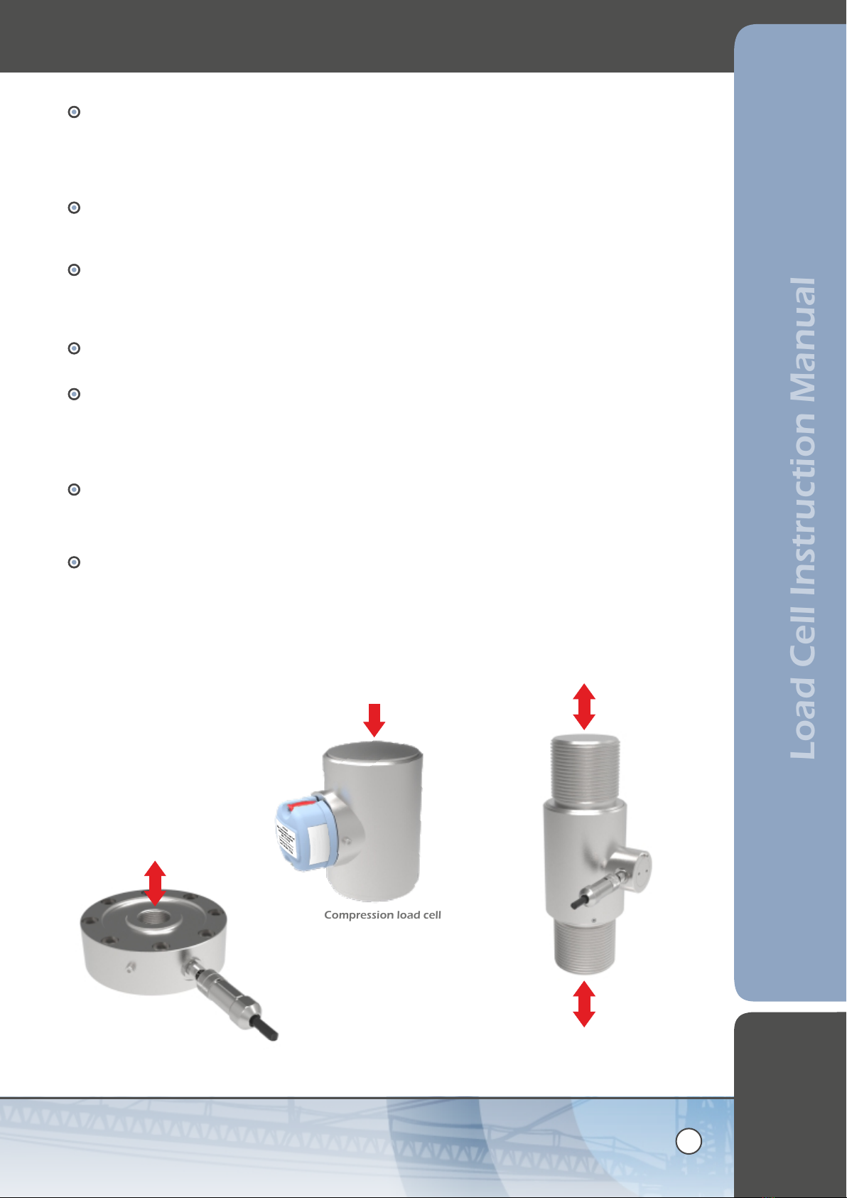
Ensure that the direction of load acting on the load cell is constant. In the case of compression cells
ensure that the load is applied centrally. Convex load buttons and caps are a convenient way of
ensuring this. In the case of tension load cells, swivel eyebolts at each end take out misalignment
during installation and service. The use of long loading rods in compression should be avoided, as
bending moment errors are magnified due to the long moment arm.
Tension and compression load cells should be loaded as shown below (Figure 2). In dynamic
applications the load cell rating should be de-rated by a factor of two, and care taken that bending is
not imposed on the transducer.
All tension and compression load cell should be installed so that side load is eliminated and generally
should not exceed 5% of the rated capacity, regardless of the rated maximum permissible value.
Depending on the design of the load cell, greater misalignments than this may lead to unacceptable
errors or damage to the load cell.
When installing tension load cells where vibration may be present, the use of thread locking
compounds or sprung vibration proofing devices (such as spring washers) is recommended.
If the load cell is fitted with a cable it must be installed in such a way as to avoid damage from impact,
abrasion or movement. The cable should be supported by cleats cable ties or in hose or conduit to
avoid flexing where possible. Ensure the cable is anchored on the ‘earth’ side of the load cell to
prevent the cable being part of the measurement loop. The installer must ensure that the cable meets
the operating requirements of the application.
Low profile load cells can be affected by both fastener torque and the quality and mechanical
stiffness of the mounting surface. For best results, the mounting surface should be flat to better than
0.03mm and be manufactured from hardened steel with a minimum hardness of 300 BHN. When
fixings are required, high tensile hexagon headed or socket cap bolts should be used, Grade 12.9.
If the load cell is fitted with a telemetry module there should be a clear line of sight between the
transmitter and receiver, and objects or structures must be kept a least one metre away from the
antenna (housed in the wireless enclosure) whenever possible. The installer should also first read the
T24 Telemetry User Manual, which can be found at the following web address:
http://www.lcmsystems.com/T24.
LOAD
Low profile tension &
compression load cell
LOAD
Tension & compression load cell
LOAD
Compression load cell
TYPE: CPW

LCM SYSTEMS
Solutions in Load Cell TechnologySolutions in Load Cell Technology
4
Load Cell Instruction Manual
Each type of load cell can be supplied with a variety of fixtures and fittings that can be used to aid
installation. All fixtures and fittings should only be used in accordance with this manual, the load cells general
arrangement drawing (GA) and the manufacturers instructions.
2.2 Fixtures & Fittings
Load cap
Mounting base
Load cell Load cell
Spherical rod
end bearing
Base plate
Load fixture
Load cell
2.3 Separately mounted telemetry enclosure
Where the physical dimensions of a load cell are too small to accommodate the telemetry enclosure, or
where the location of the load cell means a clear line of site to the receiver is not possible, then a separately
mounted telemetry enclosure can be used. The maximum permissible cable length between the load cell and
the telemetry enclosure is 2.5 metres.
Checks to the cable gland or connector supplied with the telemetry enclosure should be performed in
accordance with the operator instructions for cabled load cells (refer to section 3.).
2.4 Wiring and Electrical Checks
The correct connection of a load cell to an instrument is critical to achieving and maintaining the performance
and reliability of the load cell.
Wiring connections are given on the calibration certificate supplied with each load cell.
Where a screened cable is fitted, that screen should be connected as indicated in the manual for the
instrument the load cell is connected to.
Cable length should not be added or removed from the load cell, as this could alter the calibration
figures.
Where junction boxes are used, check the connections are good quality and securely connected. Clean
the enclosure and check that it is free from moisture.
Load cell cabling must be kept away from high power cables and equipment, high output RF equipment
and inductive loads and generators. Cables must not be run alongside power cables.
2.5 Load Cell Output Options
The load cell can be fitted with a variety of built in (in-cell) signal conditioning boards, to offer either
analogue, voltage, current signals or RS485 digital signals (in various protocols). When a wireless signal is
required, the load pin can be fitted with a T24 Telemetry Module as shown in Figure 1.

DCELL
The DCELL Digital Signal Conditioning (amplifier) board offers high speed, RS485 and CANBus outputs in
several protocols.
DCELL Communication: RS485 Baud Rate
Protocols
See the DCELL Datasheet and Instruction Manual for further details:
5
Load Cell Instruction Manual
ICA
The ICA analogue signal conditioning (amplifier) board is available in six versions, offering a range of
current and voltage outputs. All amplifiers have a wide operating voltage range.
ICA1 - 3 wire, 0.1 to 10.1V
ICA2 - 3 wire, 0.1 to 5.1V
ICA3 - 4 wire, ±10V
ICA4 - 3 wire, 4 to 20mA
ICA5 - 2 wire, 4 to 20mA
ICA6, 3 wire , ±10V
See the ICA Datasheet and Instruction Manual for further details:
2400 Min to 230K Max
ASCII
MANTRABUS II
Modbus RTU
MANTRACAN
Telemetry
The T24 product range uses high performance two-way radio communication which operates on the 2.4
GHz licence free frequency. Each load cell fitted with the telemetry module requires either a T24 handheld
device, digital/analogue interface or a base station and PC to communicate with. See the T24 User Manual
for further details on the T24 range of products:
2.6 Instrumentation and Display Set Up
The electrical output of the load cell should be connected only to instrumentation with a high enough
input impedance, preferably 1Mohm or greater, in order to prevent loading effects on the output sensitivity
of the load cell. LCM Systems offers a wide range of digital and analogue instruments ensuring compatibility.
When setting up your load cell the following points should be acknowledged:
The zero load output given on the calibration certificate is the output of the load cell when no load is
applied.
Check the calibration certificate for details of the load cell output.
http://www.lcmsystems.com/ICA_In-Cell_Analogue_Strain_Gauge_Amplifier
http://www.lcmsystems.com/DCELL_In-Cell_Digital_Strain_Gauge_to_Data_Converter
http://www.lcmsystems.com/T24
LCM SYSTEMS
Solutions in Load Cell TechnologySolutions in Load Cell Technology
6
Load Cell Instruction Manual
2.7 Checks After Installation
With the load cell installed, check that when a load is applied the output is in the correct direction in
accordance with the calibration certificate. Incorrect positive or negative outputs could be a result of
incorrect electrical connections or a side force is being applied to the load cell. Refer back to section 1.5
and figure 2 for details on correct loading.
When applying load to the load cell use the calibration certificate for reference as to the output observed
at certain loads. If this is not the same then check the following:
a. All electrical connections are correct i.e. to an instrument or junction box.
b. If a connector is fitted, check that it is fully mated.
For wireless load cells, check the receiver communicates with the load cell at the desired operating
range. Signal obstruction or reflection can significantly reduce transmission range and even cause signal
loss.
3. CABLE INFORMATION
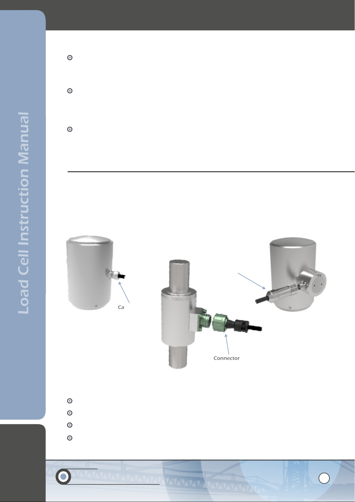
All non wireless load cells are fitted with either a cable gland or connector assembly. Cable exits are either
perpendicular to the load direction or mounted radially from a boss. See below for examples. All wiring
colours and connector pin details are shown on the calibration certificate supplied with each load cell. The
removal or replacing of the cable gland or bulkhead connector is not recommended, and any adjustment or
repair should either be preformed by LCM systems or by a suitably qualified engineer.
Connector
Cable gland
Connector
3.1 Cable gland and connector configurations
3.2 Mating and de-mating a connector assembly
Check both halves of the connector for any damage or obstructions.
Align the connector assembly and mate the two halves. Press firmly to ensure they are fully engaged.
Tighten the locking sleeve (finger tight only) to complete the mating process.
Always fully disengage the locking sleeve before attempting to un-mate the connector.

7
Load Cell Instruction Manual
4. ONGOING MAINTENANCE AND CARE
4.1 Warnings/Hazards
Tension and compression load cells are highly stressed devices and commonly have safety factors between
three and five times the rated capacity under static conditions. Fatigue applications and environmental
factors can contribute to reducing this margin.
The user should determine media effects on the exposed load cell materials. Where a corrosive environment
is present, load cells can often be manufactured from corrosion resistant materials or alternatively, isolation
barriers can be employed between the corrosive environment and the load cell. The following points should
be followed to avoid potentially dangerous situations and/or damaging the load cell:
Check for excessive wear on the load cell which could compromise performance or the IP rating.
Tension and compression load cells are sealed units which should not be dismantled. When an
amplifier is fitted, removing the cap is permitted, but only to adjust the span and zero when performing
a calibration. This should only be done by a competent person. Damaged load cells should be returned
to LCM Systems for repair and re-calibration.
The accuracy of the system is dependent upon correct installation of the load cell.
Tension and compression load cells must not be subjected to shock loads, such as using a hammer to
force the load cell into position.
Load cell material and any applied treatments (heat treatments etc.) should be verified as suitable for
the environment before the load cell is installed. Some heat treatments which LCM use are not suitable
for marine environments/high chloride (for example, 17-4PH heat treated to H900).
Fixing methods (high tensile bolts, rod end fittings or mounting bases) must always be installed as to
the general arrangement (GA) drawing or to the manufacturers instructions.
Avoid use within 20 to 30 minutes of rapid changes in temperature, for example moving the device
from a cold vehicle to a warm room. The change in temperature can affect the accuracy of the device.
The operating temperature is -20 to +70ºC or -4 to 158ºF.
Do not weld near to installed load cells, as leakage currents may destroy the load cells electric circuits.
Load cells should not be handled or carried by means of the cable.
4.2 Calibration
All LCM Systems load cells are calibrated in UKAS traceable test machines to best simulate normal loading
conditions.
We endeavour to match the loading conditions that would be experienced in service but it is not possible
to totally simulate the on-site structure for every load cell manufactured. It is for this reason that for
optimum system accuracy, a calibration in the final assembly is recommended. On-site calibration should be
performed in accordance with the manual for the instrument the load cell is connected to.
As all load cells are subject to deterioration due to use, mistreatment, drift or ageing, calibration at regular
intervals should to be carried out to establish how the load cell is currently performing. Load cells can also
become less reliable due to electrical influence, mechanical effects and instrumentation faults. Unless
calibrations are routinely carried out, load measurement readings can become less accurate, with the user
potentially being unaware that they are using compromised data.
Annual calibration is recommended as the standard interval to ensure that measurements are always as
accurate as possible, which is particularly important if being used for safety critical applications. However,
more frequently than one year may be advisable if the load cell is being used in a particularly harsh
environment or arduous operational conditions (high vibration levels, excessive cyclic loading).

LCM SYSTEMS
Solutions in Load Cell TechnologySolutions in Load Cell Technology
8
Load Cell Instruction Manual
4.3 Inspection and Repair
Repair
Only LCM Systems personnel are authorised to carry out a repair to or service their products. All repairs or
servicing will be carried out in the premises of LCM Systems. The unit is not serviceable outside of LCM
Systems premises.
Inspection
All LCM Systems load cells should be subject to periodic inspection, which should include, but is not
exclusive to the following checks:
Completion of the checks after installation, see section 2.7 (Checks After Installation).
Check output at zero load (shift in zero offset). Verify against calibration certificate.
Inspect to see if the load cell has been damaged/worn or chemically attacked (from a corrosive
environment or lubricants etc.).
For cabled versions, verify the integrity of the cable.
For wireless versions, inspect the batteries to ensure they are the correct type and have been installed
correctly. The battery holder shows pictorially the correct orientation. Check for any signs of water
ingress in the battery compartment and for any signs of battery corrosion.
After any serious operating incident, repeat first five checks above.
4.4 Storage
When not in use load links should be stored undercover in a dry environment (max humidity 95% non-
condensing) at a storage temperature of -40ºC to +85ºC.
5. NOTICES
The copyright and all rights of a like nature in respect of this document in any part of the world are the
property of LCM Systems Ltd.
No part of this document may be reproduced or transmitted in any form or by any means, whether
electronic, mechanical, photocopying, recording or otherwise, nor used for tendering or manufacturing, nor
communicated to any other person without the written permission of LCM Systems Ltd.
The recipient of this document, as its registered holder, must exercise due diligence in ensuring that the
above conditions are observed. (errors and omissions excepted). Any enquires relating to this document or
its contents should be addressed, in writing, in the first instance to LCM Systems Ltd.
LCM Systems Ltd reserve the right to make changes to its products and specifications without notice.
5.1 Copyright
LCM Systems is a specialist provider of standard and bespoke load cells, load pins, load shackles, load links
and associated instrumentation, with over 30 years' experience in supplying innovative load measurement
solutions to many different industries worldwide. Whatever the application and however demanding the
environment, we can provide a system to meet your needs.
5.2 About LCM Systems
9
Load Cell Instruction Manual
IF IN DOUBT ABOUT ANY ASPECT OF THE SELECTION,
INSTALLATION OR USE OF A TENSION & COMPRESSION
LOAD CELL, CONTACT LCM SYSTEMS FOR ADVICE
BEFORE INSTALLING

LCM Systems Ltd
Unit 15, Newport Business Park
Barry Way, Newport
Isle of Wight PO30 5GY UK
Tel: +44 (0)1983 249264
Fax: +44 (0)1983 249266
www.lcmsystems.com
www.lcmsystems.com
Issue 1
Issue date: /0 /2027 5 22
APPROVED
(Unapproved if printed)
This manual suits for next models
7
Table of contents
Other LCM SYSTEMS Industrial Equipment manuals

Popular Industrial Equipment manuals by other brands

STIEBEL ELTRON
STIEBEL ELTRON HSBC 225 S Operation and installation manual

EPPINGER
EPPINGER PSC SVC Product information

Texas Automation Products
Texas Automation Products DES-42 C4 manual

eqss
eqss JLG ES Series installation manual

Omron
Omron V460-H Network Connection Guide

Lincoln Electric
Lincoln Electric Statiflex 6000-MS Operator's manual


