LD IMA 120 User manual

IMA 120/240
INSTALLATION MIXING AMPLIFIER (125 W / 240 W) @ 4 0HMS / 100 V / 70 V
LDIMA120 / LDIMA240
USER´S MANUAL
BEDIENUNGSANLEITUNG
MANUEL D´UTILISATION
MANUAL DE USUARIO
INSTRUKCJA OBSŁUGI
MANUALE D´USO

CONTENTS / INHALTSVERZEICHNIS / CONTENU / CONTENIDO / TREŚĆ / CONTENUTO
ENGLISH
INFORMATION ON THIS USER MANUAL 4
PROPER USE 4
DEFINITIONS AND SYMBOL EXPLANATIONS 4
SAFETY INSTRUCTIONS 5
INSTRUCTIONS FOR INDOOR INSTALLATION
EQUIPMENT 8
PACKAGING CONTENT 9
INTRODUCTION 9
CONNECTIONS, OPERATING AND DISPLAY ELEMENTS 10
CONNECTION EXAMPLES 17
TERMINAL BLOCK CONNECTIONS 18
JUMPER FOR EMERGENCY SIGNAL TO AUX OUT 19
RACK MOUNTING 20
UNDER-TABLE MOUNTING 21
CARE, MAINTENANCE AND REPAIR 22
TECHNICAL DATA 23
DISPOSAL 27
MANUFACTURER’S DECLARATIONS 28
DEUTSCH
INFORMATIONEN ZU DIESER
BEDIENUNGSANLEITUNG 29
BESTIMMUNGSGEMÄSSER GEBRAUCH 29
BEGRIFFS- UND SYMBOLERKLÄRUNGEN 29
SICHERHEITSHINWEISE 30
HINWEISE FÜR INDOOR-INSTALLATIONSGERÄTE 33
LIEFERUMFANG 34
EINLEITUNG 34
FEATURES 35
ANSCHLÜSSE, BEDIENUNG UND ANZEIGEELEMENTE 36
ANSCHLUSSBEISPIELE 43
KLEMMLEISTENANSCHLÜSSE 44
JUMPER FÜR NOTSIGNAL AN AUX-OUT 45
RACK-MONTAGE 46
UNTERTISCH-MONTAGE 47
PFLEGE, WARTUNG UND REPARATUR 48
TECHNISCHE DATEN 49
ENTSORGUNG 53
HERSTELLERERKLÄRUNGEN 54
FRANCAIS
INFORMATIONS SUR CE MANUEL D‘UTILISATION 56
UTILISATION RÉGLEMENTÉE 56
EXPLICATIONS DES TERMES ET DES SYMBOLES 56
CONSIGNES DE SÉCURITÉ 57
INSTRUCTIONS POUR LES APPAREILS
D’INSTALLATION À L’INTÉRIEUR 60
CONTENU DU CARTON 61
INTRODUCTION 61
BRANCHEMENTS, UTILISATION ET INDICATEURS 63
EXEMPLES DE CONNEXION 70
CONNECTEURS EUROBLOCK 71
CAVALIER POUR ENVOI DU SIGNAL D'URGENCE
VERS LA SORTIE AUXILIAIRE 72
MONTAGE EN RACK 73
MONTAGE SOUS UNE TABLE 74
ENTRETIEN, MAINTENANCE ET RÉPARATIONS 75
CARACTÉRISTIQUES TECHNIQUES 76
MISE EN DÉCHETTERIE 81
DÉCLARATIONS DU FABRICANT 82
ESPAÑOL
INFORMACIÓN SOBRE ESTE MANUAL DEL USUARIO 84
USO CONFORME A LA NORMATIVA 84
EXPLICACIONES DE TÉRMINOS Y SíMBOLOS 84
INSTRUCCIONES DE SEGURIDAD 85
NOTAS PARA LAS UNIDADES DE INSTALACIÓN
EN INTERIOR 88
CONTENIDO DEL PAQUETE 89
INTRODUCCIÓN 89
CONEXIONES, MANDOS E INDICADORES 91
EJEMPLOS DE CONEXIÓN 98
CONEXIONES DEL BLOQUE DE TERMINALES 99
PUENTE PARA ENVIAR LA SEÑAL
DE EMERGENCIA A LA SALIDA AUX OUT 100
MONTAJE EN RACK 101
MONTAJE DEBAJO DE LA MESA 102
CUIDADO, MANTENIMIENTO Y REPARACIÓN 103
DATOS TÉCNICOS 104
DISPOSICIÓN 109
DECLARACIONES DEL FABRICANTE 110

POLSKI
INFORMACJE NA TEMAT NINIEJSZEJ
INSTRUKCJI OBSŁUGI 112
STOSOWANIE ZGODNIE Z PRZEPISAMI 112
OBJAŚNIENIA TERMINÓW I SYMBOLI 112
INSTRUKCJE BEZPIECZEŃSTWA 113
WSKAZÓWKI DOTYCZĄCE JEDNOSTEK
INSTALACYJNYCH W POMIESZCZENIACH 116
ZAKRES DOSTAWY 117
WPROWADZENIE 117
PRZYŁĄCZA, ELEMENTY OBSŁUGI I WSKAŹNIKI 119
PRZYKŁADY POŁĄCZEŃ 126
POŁĄCZENIA LISTWY ZACISKOWEJ 127
ZWORA DLA SYGNAŁU ALARMOWEGO
DO WYJŚCIA AUX 128
MONTAŻ W SZAFIE RACK 129
MONTAŻ PODBLATOWY 130
PIELĘGNACJA, KONSERWACJA I NAPRAWA 131
DANE TECHNICZNE 132
DYSPOZYCJA 137
OŚWIADCZENIA PRODUCENTA 138
ITALIANO
INFORMAZIONI SU QUESTO MANUALE
DI ISTRUZIONI 140
UTILIZZO IN CONFORMITÀ ALLE NORMATIVE 140
SPIEGAZIONI DI TERMINI E SIMBOLI 140
ISTRUZIONI DI SICUREZZA 141
NOTE PER LE UNITÀ DI INSTALLAZIONE INTERNE 144
MATERIALE COMPRESO NELLA FORNITURA 145
INTRODUZIONE 145
CONNESSIONI, ELEMENTI DI COMANDO E
DI VISUALIZZAZIONE 147
ESEMPI DI CONNESSIONE 153
COLLEGAMENTI DELLA MORSETTIERA 154
PONTICELLO AD AUX OUT
PER SEGNALE DI EMERGENZA 155
MONTAGGIO RACK 156
MONTAGGIO SOTTO IL TAVOLO 157
CURA, MANUTENZIONE E RIPARAZIONE 158
DATI TECNICI 159
SMALTIMENTO 163
DICHIARAZIONI DEL PRODUTTORE 164

4
ENGLISH
YOU HAVE MADE THE RIGHT CHOICE!
This device has been developed and manufactured to the highest quality standards to ensure many
years of problem-free operation. This is what LD Systems stands for with its name and many years of
experience as a manufacturer of high-quality audio products. Please read these operating instructions
carefully so that you can quickly get the most out of your new LD Systems product.
You can find more information about LD Systems on our website WWW.LD-SYSTEMS.COM
INFORMATION ON THIS USER MANUAL
• Carefully read the safety instructions and the entire manual before operating the device.
• Observe the warnings on the device and in the user manual.
• Always keep the user manual within reach.
• If you sell or pass on the device, it is important that you also include this user manual,
as it is an integral part of the product.
PROPER USE
The product is a device for professional audio installations!
The product has been developed for professional use in the field of audio installation
and is not suitable for use in households!
Furthermore, this product is intended for installation by qualified persons with
expertise and for operation by instructed persons!
Use of the product outside the specified technical data and operating conditions
is considered improper use!
Liability for damage and third-party damage to persons and property due to inappropriate
use is excluded!
The product is not suitable for:
• Use by persons (including children) with limited physical, sensory or mental abilities
or lack of experience and knowledge.
• Children (children must be instructed not to play with the device).
DEFINITIONS AND SYMBOL EXPLANATIONS
1. DANGER: The word DANGER, possibly in combination with a symbol, indicates immediately
dangerous situations or conditions for life and limb.
2. WARNING: The word WARNING, possibly in combination with a symbol, indicates potentially
dangerous situations or conditions for life and limb.
3. CAUTION: The word CAUTION, possibly in combination with a symbol, is used to indicate
situations or conditions that may lead to injury.
4. ATTENTION: The word ATTENTION, possibly in combination with a symbol, refers to
situations or states that can lead to damage to property and/or the environment.
ITALIANO
POLSKI
ESPAÑOL
FRANCAIS
DEUTSCHENGLISH

5
This symbol identifies hazards that can cause electric shock.
This symbol identifies hazardous areas or hazardous situations.
This symbol indicates hazards caused by hot surfaces.
This symbol indicates dangers due to high volume levels.
This symbol denotes a device that does not contain
any user-serviceable parts.
This symbol indicates additional information on the operation of the product.
This symbol indicates electrical equipment designed primarily for indoor use.
SAFETY INSTRUCTIONS
DANGER:
1. Do not open the device and do not perform any modifications.
2. If your device no longer functions properly, if liquids or objects get inside it or if it has
been damaged in any other way, switch it off immediately and disconnect it from the
mains. The device may be repaired only by authorised repair technicians.
3. For devices of protection class 1, the protective conductor must be connected correctly.
Never disconnect the protective conductor. Devices of protection class 2 do not have a
protective conductor.
4. Ensure that live cables are not kinked or otherwise mechanically damaged.
5. Never bypass the device fuse.
WARNING:
1. The device may not be operated if it shows obvious signs of damage.
2. The device may only be installed in a voltage-free state.
3. If the mains cable of the appliance is damaged, do not operate the appliance.
4. Permanently connected power cables may only be replaced by a qualified person.
DEUTSCHFRANCAIS
ESPAÑOL ENGLISH
ITALIANO POLSKI

6
ATTENTION:
1. Do not operate the unit if it has been exposed to large temperature fluctuations
(for example, after transport). Moisture and condensation can damage the device.
Switch on the device only when it has reached room temperature.
2. Make sure that the voltage and frequency of the mains supply correspond to the values
indicated on the unit. If the device has a voltage selector switch, do not connect the
device until it has been set correctly. Use only suitable power cables.
3. To disconnect the unit from the mains at all poles, it is not sufficient to
press the on/off switch on the unit.
4. Make sure that the fuse used corresponds to the type printed on the unit.
5. Make sure that appropriate measures have been taken against overvoltage
(e.g. lightning strike).
6. Observe the specified maximum output current on units with Power Out connection.
Ensure that the total current consumption of all connected devices does not exceed
the specified value.
7. Replace pluggable mains cables only with original cables.
DANGER:
1. Danger of suffocation! Plastic bags and small parts must be kept out of reach of persons
(including children) with reduced physical, sensory or mental capabilities.
2. Danger from falling down! Make sure that the device is securely installed and will not fall
down. Only use suitable stands or mounts (particularly for fixed installations). Ensure that
accessories are properly installed and secured. Ensure that applicable safety regulations
are observed.
WARNING:
1. Use the appliance only in the manner intended.
2. Operate the appliance only with the accessories recommended and intended
by the manufacturer.
3. During installation, observe the safety regulations applicable in your country.
4. After connecting the unit, check all cable routes to avoid damage or accidents,
e.g. due to tripping hazards.
5.
Always observe the specified minimum distance to normally flammable materials!
Unless explicitly stated, the minimum distance is 0.3m.
CAUTION:
1. In the case of moving components such as mounting brackets or other moving
components, there is a possibility of jamming.
2. In the case of units with motor-driven components, there is a risk of injury from the
movement of the unit. Sudden movement of the device can cause shock reactions.
ITALIANO
POLSKI
ESPAÑOL
FRANCAIS
DEUTSCHENGLISH

7
ATTENTION:
1. Do not install or operate the appliance near any radiators, heat registers, stoves or other
heat sources. Ensure that the device is always installed in such a way that it is sufficiently
cooled and cannot overheat.
2. Do not place ignition sources such as burning candles near the appliance.
3. Ventilation openings must not be covered and fans must not be blocked.
4. Use the original packaging or packaging provided by the manufacturer for transport.
5. Avoid shock or impact to the unit.
6. Observe the IP protection class as well as the ambient conditions such as temperature
and humidity according to the specification.
7. Devices can be constantly further developed. In the event of deviating information on
operating conditions, performance or other device properties between the user manual
and the device labelling, the information on the device always takes priority.
8. The unit is not suitable for tropical climates and for operation above 2000 m above sea
level.
9. Unless explicitly stated, the unit is not suitable for operation in marine conditions.
CAUTION:
Connecting signal cables can cause a lot of noise. Make sure that devices connected
to the output are muted when plugged in. Otherwise, noise levels may cause damage.
PLEASE NOTE:
For conversion or retrofit sets or accessories provided by the manufacturer,
it is essential to observe the instructions included.
CAUTION: HIGH VOLUME AUDIO PRODUCTS!
This device is designed for professional use.
The commercial operation of this device is subject to the applicable national regulations and
guidelines for accident prevention.
Hearing damage due to high volume and continuous exposure: Use of this product may
produce high sound pressure levels (SPL) which may cause hearing damage. Avoid exposure
to high volumes.
DEUTSCHFRANCAIS
ESPAÑOL ENGLISH
ITALIANO POLSKI

8
SIGNAL TRANSMISSION BY RADIO (e.g. W-DMX or audio radio systems, Bluetooth):
The quality and performance of wireless signal transmissions generally depends on the
ambient conditions.
The following factors can impact range and signal stability, for example:
• Shielding (e.g. masonry, metal structures, water)
• High volume of radio traffic (e.g. powerful wireless LAN networks)
• Interference
• Electromagnetic radiation (e.g. LED video screens, dimmers)
All range specifications refer to free-field application with visual contact
and without interference!
The operation of transmission systems is subject to official regulations.
These can vary from region to region and must be checked by the operator
before commissioning (e.g. radio frequency and transmission power).
WARNING:
Devices with wireless signal transmission are not suitable for use in sensitive areas
in which radio operation can lead to potential detrimental effects. These include:
• Hospitals, health centres or other healthcare facilities that provide patient
treatment with skilled personnel and equipment.
• Hazardous areas Class I, II and III
• Restricted areas
• Military facilities
• Aircraft or vehicles
• Areas where the use of mobile phones is prohibited
INSTRUCTIONS FOR INDOOR INSTALLATION EQUIPMENT
1. Units for installation applications are designed for continuous operation.
2. Equipment for indoor installation is not weather-resistant.
3. Surfaces and plastic parts can also age in installation equipment, e.g. due
to UV irradiation and temperature fluctuations.
This generally does not impair functionality.
4. With permanently installed devices, the accumulation of impurities, e.g. dust,
is to be expected. Always observe the care instructions.
5. Unless explicitly stated otherwise on the device or in the technical data,
the devices are intended for installation heights of less than 5 m.
ITALIANO
POLSKI
ESPAÑOL
FRANCAIS
DEUTSCHENGLISH

9
PACKAGING CONTENT
LD IMA 120
Remove the product from the packaging and remove all packaging material.
Please check the completeness and integrity of the delivery and notify your distribution
partner immediately after purchase if the delivery is not complete or if it is damaged.
Product includes:
• 1x IMA 120 mixing amplifier
• 1x power cable
• 1 set of terminal blocks
• User manual
LD IMA 240
Remove the product from the packaging and remove all packaging material.
Please check the completeness and integrity of the delivery and notify your distribution
partner immediately after purchase if the delivery is not complete or if it is damaged.
Product includes:
• 1x IMA 240 mixing Amplifier
• 1x power cable
• 1 set of terminal blocks
• User manual
INTRODUCTION
For permanent installations, the flexibility and versatility of the mixing amplifier are particularly
important, in addition to an inconspicuous appearance. Different signal sources and microphones must
be able to be connected. In case of emergencies, the input signals must be easily muted to allow for
announcements or emergency calls. With the IMA 120 or IMA 240, LD Systems adds two more mixing
amplifiers to the IMA series, which leaves nothing to be desired in terms of design and flexibility.
Its compact design in a 9.5-inch chassis, multiple connectivity options including Bluetooth for wireless
connection of music sources, and multi-level priority switching guarantee seamless integration into
commercial and industrial applications. The IMA 120 or IMA 240 offers four priority levels for emergency
calls and microphone / line inputs for various signal and music sources. Optionally, an automatic
standby mode can also be activated to further reduce power consumption.
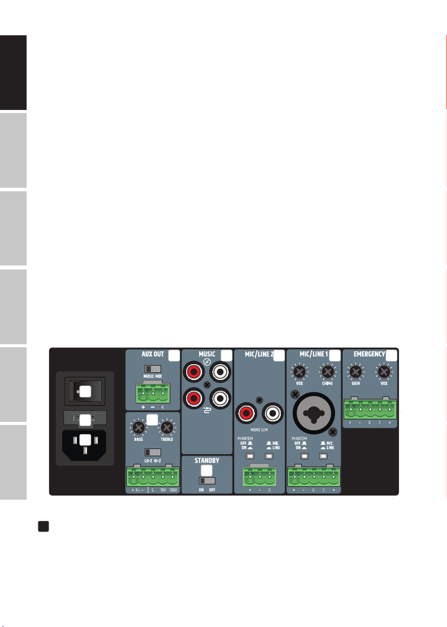
The mixer amplifier has two priority contact closures: one for the emergency input, which mutes all
other signal sources on the unit, and one for the microphone inputs, which mutes the music signal
sources. The outputs offer a power of 125 W or 240 W at 4 ohms, a 2-band EQ for bass and treble and a
70 V / 100 V tap. Using the High-Z / Low-Z selector switch, the output signal can be completely separated
from the output transformer, ensuring optimum frequency response in low impedance applications.
External power amplifiers, active subwoofers or systems for music on hold can be combined with the
IMA 120 or IMA 240 via the integrated aux output. With the Music Mix selector switch, you also decide
whether the entire mix or only the selected music signal source is to be transmitted to the aux output.
The intuitive design of the control panel with capacitive buttons for selecting the music signal source,
the clear layout of the rear panel and the compact 9.5-inch format ensure that there are no problems
when installing the mixing amplifier.
DEUTSCHFRANCAIS
ESPAÑOL ENGLISH
ITALIANO POLSKI

10
FEATURES
• Line input for emergency signal with contact closure
• 2 microphone/line input sockets with microphone/line switch and switchable 24 V phantom power
• Switchable chime feature in Mic/Line 1 channel
• 2 line inputs with RCA sockets and Bluetooth 4.0 interface (mono summed)
• Gain control and clip LED indicator for emergency and mic/line inputs
• Class-D amplifier with 125 W (IMA 120) or 240 W (IMA 240) output power
• Output for low impedance speakers and 70/100 V outputs with LO-Z/HI-Z switching. In low impedance
mode, the audio signal is completely isolated from the transformers for optimal frequency response
• Balanced AUX line output with Music-Mix switch, for controlling external amplifiers, active subwoofers
or music-on-hold systems
• Music mix switch on AUX out for setting whether AUX out plays the overall mix or only the selected
music source
• Separate tone control for treble and bass on the back of the device
• Four priority levels for comprehensive integration options
• Switchable auto standby mode for reduction of energy consumption
• User-friendly control panel design for intuitive operation with capacitive control panels for selecting
music source and for Bluetooth pairing
• Clearly arranged and labelled sockets and operating elements on the back for easy installation
• Universal wide-range switching power supply
• Format: Half rack width, 2 U
• Optional: Rack mounting kit (IMA RK) for installation of one or two IMA 30/60/120/240 units in a 19" rack
CONNECTIONS, OPERATING AND DISPLAY ELEMENTS
10
2
1
3XLR f
1
3
2
XLR m
1
2
3
45678
9
10
Connections, operating and display elements of the two units IMA 120 and IMA 240 are identical
1POWER SOCKET
IEC socket for power supply to the unit (mains cable included).
ITALIANO
POLSKI
ESPAÑOL
FRANCAIS
DEUTSCHENGLISH

11
2FUSE
Fuse holder for 250 V fuses (5 x 20 mm). IMPORTANT NOTE: Replace the fuse only with a fuse of the same
type (see printed instructions on the housing). Should the fuse blow repeatedly, please contact an
authorised service centre.
3ON/OFF
Rocker switch for switching the device on and off.
4EMERGENCY
The 5-pole terminal block connection is used to install an acoustic emergency call system. The poles
+, - and G correspond to a balanced line input. The poles C and + are used to connect a separate mute
switch (terminal block included). The Emergency contact closure (pins C and +) allows muting of all
other input channels, independently from the VOX settings.
CLIP: The red CLIP LED indicates when the input is operated at the distortion limit. Reduce the signal
level using the GAIN control or on the playback device so that the CLIP LED is no longer lit.
VOX: The VOX (Voice Operated Exchange) control offers the possibility to set a threshold for the
emergency audio signal, thus activating an automatic mute circuit. When the level at the EMERGENCY
input reaches the set threshold, all other microphone and line channels are muted. This ensures that
the emergency signal can be heard clearly. In addition, the EMERG indicator at the front of the amplifier
lights up in this case. As soon as the level of the emergency signal falls below the set threshold, the
muting of the other channels is cancelled again and the EMERG display goes out. With the appropriate
setting, the EMERGENCY channel always has the highest priority. The emergency signal is transferred
internally directly to the LINE OUT audio output. If the VOX control is set to minimum (turned all the way
to the left), the automatic muting via VOX circuitry is deactivated and the EMERGENCY channel can be
used as an additional line channel.
GAIN: Control for adjusting the pre-amplification of the incoming audio signal. Adjust the gain control
so that the channel's clip LED only lights up briefly during signal level peaks. Avoid permanent glow
of the clip LED by reducing the pre-amplification. It may also be necessary to reduce the signal level
on the source device. The level of the emergency signal is not influenced by the current setting of the
main volume control (Master Volume), but is adjusted via the GAIN control.
5MIC/LINE 1
Microphone/line channel with switchable gong function (signal tone). The connection can be made via
the XLR/jack combo socket as well as via terminal block. In this case, the poles +, - and G on the terminal
block connection are intended for the balanced input signal.
The poles C and + are used to connect a separate mute switch (terminal block included).
The contact closure offers the possibility to mute the MUSIC channel via an external switch/button.
In addition, the internal gong/signal tone function can be controlled in this way if the circuit is
activated (see point 6 MIC/LINE 2, CHIME).
MIC/LINE: If a line signal is present at the XLR/jack combo socket or at the terminal block switch MIC/
LINE channel 1 to LINE mode via the associated MIC/LINE switch (switch pressed). If a microphone is
connected, activate MIC mode via the MIC/LINE switch (switch not pressed).
PHANTOM ON/OFF: When using a condenser microphone, it is necessary to activate the 24 V phantom
power supply (PHANTOM ON/OFF switch pressed: ON). Always make sure that the microphone is
connected and the channel volume is set to minimum before switching on the phantom power.
Before disconnecting the microphone from the unit again, deactivate the phantom power and
turn the channel volume to minimum.
DEUTSCHFRANCAIS
ESPAÑOL ENGLISH
ITALIANO POLSKI

12
GAIN: Control for adjusting the pre-amplification of the incoming audio signal. Adjust the gain control
so that the channel's clip LED only lights up briefly during signal level peaks. Avoid permanent glow of
the clip LED by reducing the pre-amplification. It may also be necessary to reduce the signal level on
the source device.
CLIP: The red CLIP LED indicates when the input is operated at the distortion limit. Reduce the signal
level on the GAIN control or on the playback device so that the CLIP LED is no longer lit.
VOX: The VOX control allows you to set an audio threshold for an automatic mute circuit for MIC/LINE
input 1, so that the MIC/LINE 2 and MUSIC channels are muted as soon as the input signal reaches the
predefined level. The PRIO LED on the front lights up when the NO contact or VOX circuit is active.
As soon as the input level of the emergency signal falls below the set threshold, the muting of the
channels is cancelled again and the PRIO LED goes out. If configured accordingly, MIC/LINE 1 has priority
over MIC/LINE 2 and MUSIC. Adjust the channel volume using control 1 on the front of the unit.
6MIC/LINE 2
Microphone/line channel with switchable gong function (signal tone). The connection can be made
via the RCA sockets (line level, a stereo signal is summed mono) or via terminal block. In this case, the
poles +, - and G on the terminal block connection are intended for the balanced input signal.
MIC/LINE: If a line signal is present at the terminal block connection, switch MIC/LINE channel 2 to LINE
mode via the associated MIC/LINE switch (switch pressed). If a microphone is connected to the terminal
strip connector, activate MIC mode via the MIC/LINE switch (switch not pressed).
PHANTOM ON/OFF: When using a condenser microphone, it is necessary to activate the 24 V phantom
power supply (PHANTOM ON/OFF switch pressed: ON). Always make sure that the microphone is
connected and the channel volume is set to minimum before switching on the phantom power.
Before disconnecting the microphone from the unit again, deactivate the phantom power and turn
the channel volume to minimum.
GAIN: Control for adjusting the pre-amplification of the incoming audio signal. Adjust the gain control
so that the channel's clip LED only lights up briefly during signal level peaks. Avoid permanent glow of
the clip LED by reducing the pre-amplification. It may also be necessary to reduce the signal level on
the source device.
CLIP: The red CLIP LED indicates when the input is operated at the distortion limit. Reduce the signal
level on the GAIN control or on the playback device so that the CLIP LED is no longer lit.
CHIME: The volume for the gong/signal tone is controlled by the CHIME control on the back of the
amplifier. When the control is turned all the way to the left, the gong/signal tone circuit is deactivated.
If the internal gong/signal tone function is active, the MIC/LINE 1, MIC/LINE 2 and MUSIC channels are
muted for the duration of the signal tone. The signal tone is triggered by means of a push-button with
normally open function, which is connected to the contacts C and + of channel MIC/LINE 1.
Adjust the channel volume using control 2 on the front of the unit.
7MUSIC
Line channel for integrating playback devices such as CD or MP3 players (a stereo signal is summed mono).
The MUSIC channel is additionally equipped with a Bluetooth module. RCA sockets for connecting two
stereo line input signal sources are available at the rear (CD symbol or cable symbol). The desired signal
source is selected via a touch-sensitive button on the front of the amplifier. Adjust the channel volume
using the MUSIC control on the front of the unit.
ITALIANO
POLSKI
ESPAÑOL
FRANCAIS
DEUTSCHENGLISH

13
8AUX OUT
The line output AUX OUT with terminal block connection is used for sending a signal, for example, to an
external amplifier, an active subwoofer or a system for telephone music on hold (terminal block
included). The MUSIC-MIX button can be used to transfer only the signal of the music channel
(MUSIC position) or the sum of all channels (MIX position) to the output.
Please note: In the factory setting, the EMERGENCY signal (emergency signal) is routed to the AUX OUT
line output via an internal jumper. If this setting is to be changed, the unit must be opened and the
corresponding jumper removed. Please refer to "JUMPER FOR EMERGENCY SIGNAL TO AUX OUT"
in this instruction manual.
9SPEAKER OUTPUT
The loudspeaker output with terminal block connection (terminal block included in the packaging)
enables to use both low-impedance loudspeakers with an impedance of at least 4 ohms (LO-Z/HI-Z
key in LO-Z position) and 70/100 V loudspeakers (LO-Z/HI-Z key in HI-Z position). Please note the correct
assignment of the terminal block poles (see illustration below). The tonal adjustment of the speaker
signal is done via the controls BASS (bass) and TREBLE (treble). The total output power of the connected
speakers should roughly correspond to the amplifier power.
10 STANDBY ON/OFF
If the standby function is activated (STANDBY in position ON), the amplifier will automatically go into
standby mode if no audio signal is detected for 20 minutes. This reduces power consumption in a
sensible way. As soon as an audio signal is present, the amplifier is automatically booted up from
standby mode and is fully operational again within approx. 3 seconds (during booting, the standby LED
on the front panel flashes white). If the STANDBY LED lights up white continuously, the unit is ready
for operation. In standby mode, the LED lights up red. In addition, the IMA 120 or IMA 240 can also be
put into standby mode manually by pressing the standby button on the front panel. In this case, the
auto-standby mode is deactivated and the unit does not start up again automatically.
Please note: When the Auto Standby switch is active, the Bluetooth connection status is also
analysed. If a Bluetooth connection with a playback device (e.g. smartphone or tablet) is detected
and Bluetooth is selected as the signal source, the unit is not automatically set to standby mode.
11
11
12
13 14
15
16
17 18
19
20
Connections, operating and display elements of the two units IMA 120 and IMA 240 are identical
DEUTSCHFRANCAIS
ESPAÑOL ENGLISH
ITALIANO POLSKI

14
11 CHANNEL 1
Volume control for channel 1 with white SIG (signal) and red CLIP LED. As soon as an audio signal is
present at channel 1 and the volume control 1 is set to the desired volume, the white signal LED lights
up. If the red CLIP LED lights up, distortion of the signal may occur.
In this case, reduce the output level of the source device or the channel volume (control 1)on the
amplifier. If distortion still occurs, please check the corresponding input stage on the back of the
amplifier (CLIP LED / GAIN).
12 CHANNEL 2
Volume control for channel 2 with white SIG (signal) and red CLIP LED. As soon as an audio signal is
present at channel 2 and the volume control 2 is set to the desired volume, the white signal LED lights
up. If the red CLIP LED lights up, distortion of the signal may occur. In this case, reduce the output level
of the source device or the channel volume (control 2) on the amplifier. If distortion still occurs, please
check the corresponding input stage on the back of the amplifier (CLIP-LED / GAIN).
13
Touch-sensitive button for selecting the audio source for the MUSIC channel (Bluetooth module, input
with CD symbol, input with cable symbol). To switch the signal source, touch the key for at least half a
second. The individual signal sources are activated in a clockwise direction.
14
Touch-sensitive button for activating the Bluetooth connection (pairing). The connection of a Bluetooth
accessory device (e.g. smartphone, tablet, etc.) with the Bluetooth module of the amplifier is done by
selecting the Bluetooth signal source (see item 13). If no external player is connected to the Bluetooth
module, this is indicated by the Bluetooth symbol flashing slowly. To connect to an external player,
press the Bluetooth pairing button for approx. 2 seconds until the Bluetooth symbol flashes faster.
Now the Bluetooth ID is visible to other Bluetooth devices. Activate the Bluetooth function of the
external player and search for nearby Bluetooth devices via the Bluetooth menu. When the LD IMA 120
or IMA 240 appears under "Available devices", you only need to select it and the connection will be
established automatically. When pairing is complete, the Bluetooth icon on the front of the device will
light up and remain on. The Bluetooth ID is no longer visible to other devices to prevent unauthorised
pairing with the Bluetooth module. Now playback can be started via the external player. If you want to
disconnect the pairing with a connected Bluetooth device again so that the Bluetooth module can be
connected to another device, press the Bluetooth button again for approx. 2 seconds. You can then
integrate the desired playback device into the setup by selecting the LD IMA 120 or IMA 240 in the
Bluetooth menu ("Connected devices") of the playback device.
15 MUSIC
Volume control for the MUSIC channel with white SIG (signal) and red CLIP LED. As soon as an audio
signal is present at the MUSIC channel and the corresponding volume control is set to the desired
volume, the white signal LED lights up. If the red CLIP LED lights up, distortion of the signal may occur.
In this case, reduce the output level of the source device or the channel volume (MUSIC control) on the
amplifier.
ITALIANO
POLSKI
ESPAÑOL
FRANCAIS
DEUTSCHENGLISH

15
16 MASTER VOLUME CONTROLLER
The main volume control is used to control the sum signal of all channels except the EMERGENCY channel.
The EMERGENCY channel bypasses the main volume control and the signal is passed directly to the
power amp and speaker output. The main volume control is equipped with a ring-shaped, three-
colour LED indicator. This LED ring remains dark when there is no signal or only a very weak signal at
the output and starts to light up as soon as a sufficient signal level is detected. If the internal limiter
intervenes, the ring lights up yellow. Red light indicates that due to a technical problem (e.g. short
circuit in the loudspeaker cable) the protection circuit of the amplifier has been activated. In this case,
the output is muted. Switch the device off. If the technical problem cannot be solved, please contact an
authorised service centre.
17 PRIO
Display field for activated priority mode of the MIC/LINE channels (priority levels 2, 3 and 4).
The priority function of the MIC/LINE channels is activated in the following three situations,
and the PRIO indicator on the front panel lights up yellow:
1. The VOX circuit is active (input signal level MIC/LINE 1 exceeds the set VOX threshold).
2. The contact between the poles C and + of the terminal block connection for channel MIC/LINE 1
is closed via a mute switch/button.
3. The gong/signal tone is played.
For more information on the channel priorities and the EMERG and PRIO indicator panels on the
front panel of the amplifier, see the PRIORITY LEVELS table in this manual.
18 EMERG
Display field for the priority feature of the Emergency channel. The EMERG indicator lights up yellow
when priority level 1 is activated by VOX emergency circuit or via a connected mute switch/button
(normally open contact). At the same time, all other input channels are muted. As soon as the contact
opens again or the emergency signal level falls below the defined VOX threshold, all channels are
unmuted and the EMERG indicator goes out.
19 STANDBY BUTTON
A short press on the standby button puts the amplifier into standby mode, and the speaker outputs
are muted. If the standby button is briefly pressed a second time , the amplifier is ready for operation
again. When standby mode is activated by pressing the standby button, reactivation of the amplifier
via the automatic standby function is not available, even if an audio signal is detected.
20 STANDBY LED
Two-colour LED to indicate the current operating status. During the start-up process, the standby LED
flashes white. The LED lights up permanently white when the start-up process is completed and the
unit is ready for operation. When the unit is put into standby mode, the LED flashes red until the
process is completed. In standby mode, the LED lights up permanently red.
DEUTSCHFRANCAIS
ESPAÑOL ENGLISH
ITALIANO POLSKI

16
PRIORITY LEVELS
PRIORITY-
LEVELS
TRIGGER SIGNAL SOURCE MUTED SIGNAL
SOURCES
ACTIVE
SIGNAL
SOURCES
FRONT DISPLAY
1Emergency VOX circuit
& normally open contact
MIC/LINE 1 EMERGENCY
SIGNAL EMERGMIC/LINE 2
MUSIC
2 MIC/LINE 1 VOX MIC/LINE 2 EMERGENCY
SIGNAL PRIO
MUSIC MIC/LINE 1
3
MIC/LINE 1, normally open
contact during gong/signal
tone Playback
MIC/LINE 1
EMERGENCY
SIGNAL PRIOMIC/LINE 2
MUSIC
4
MIC/LINE 1, normally open
contact after gong/signal
tone Playback
MUSIC
EMERGENCY
SIGNAL
PRIO
MIC/LINE 1
MIC/LINE 2
5– –
EMERGENCY
SIGNAL
–
MIC/LINE 1
MIC/LINE 2
MUSIC
ITALIANO
POLSKI
ESPAÑOL
FRANCAIS
DEUTSCHENGLISH

17
CONNECTION EXAMPLES
Microphone Signal
Microphone Signal
Mute Contact
Mute Contact
12
The connection for a mute switch/button in MIC/LINE channel 1 can be used for two devices at the same
time (muting a music signal or activating the gong/signal tone). In this case, the mute contacts of both
units must be connected to the poles C and + of the terminal block connection for MIC/LINE 1.
Microphone Signal
Microphone Signal
Mute Contact
Mute Contact
12
When wiring terminal blocks, please
observe the correct assignment of the
poles/terminals (see illustration under the
connection examples for terminal blocks).
The manufacturer accepts no liability for
damage caused by faulty wiring!
For more information on the correct wiring
of terminal block connections
("Terminal Blocks"), see the TERMINAL BLOCK
CONNECTIONS section of this manual.
DEUTSCHFRANCAIS
ESPAÑOL ENGLISH
ITALIANO POLSKI

18
TERMINAL BLOCK CONNECTIONS
LINE OUTPUT AUX OUT
+ -/G
balanced unbalanced
SPEAKER CONNECTIONS (LOW IMPEDANCE, 100 V AND 70 V LOUDSPEAKERS)
2
1
3XLR f
1
3
2
XLR m
2
1
3XLR f
1
3
2
XLR m
2
1
3XLR f
1
3
2
XLR m
INPUTS CHANNELS 1 AND 2
balanced unbalanced
+ -/G
INPUTS EMERGENCY CHANNEL
2
1
3XLR f
1
3
2
XLR m
ITALIANO
POLSKI
ESPAÑOL
FRANCAIS
DEUTSCHENGLISH

19
JUMPER FOR EMERGENCY SIGNAL TO AUX OUT
In the factory setting, the EMERGENCY signal is routed to the AUX OUT line output via an internal jumper.
If this setting is to be changed, the unit must be opened and the corresponding jumper removed.
IMPORTANT:
DANGER: RISK OF ELECTRIC SHOCK! DANGEROUS VOLTAGES INSIDE THE UNIT!
Opening the unit to change the configuration using jumpers requires technical expertise and
may only be carried out by appropriately trained persons! If you are not qualified to do so,
never carry out such interventions yourself, but contact trained service technicians.
Take care when opening the amplifier and changing the configuration. This way you avoid damage to
the appliance and personal injury. Follow the individual steps in these instructions carefully.
The manufacturer accepts no liability for damage to property or personal injury caused by improper handling.
1. Disconnect the amplifier completely from the mains (pull out the mains plug)!
2. Disconnect all cables from the amplifier.
3. Wait at least one minute before opening the housing to make sure that there is no dangerous
voltage inside!
4. Loosen and remove the two screws on the sides of the amplifier A, the four correspondingly
labelled screws on the back Band one screw on the top of the amplifier C(nine screws in total)
using a suitable tool. Note the positions of the three different types of screws.
5. Pull the housing cover backwards off the housing.
6. Pull the jumper shown in figure 2 Doff the contacts (inside rear of unit).
7. Slide the housing cover back onto the housing from behind and screw it tight with the screws
you loosened earlier.
Now the emergency signal of the EMERGENCY channel is no longer routed to the AUX OUT output.
B
A
AB
B
C
D
D
DEUTSCHFRANCAIS
ESPAÑOL ENGLISH
ITALIANO POLSKI

20
RACK MOUNTING
(Rack mounting kit LDIMARK optionally available)
The optionally available LDIMARK rack-mount kit includes housing adapters and connectors for
fixed installation of IMA 120 or IMA 240 mixer amplifiers (single or two side-by-side) in a 19" rack.
The mounting kit includes the following components:
2 rack adapters with short sides A, 1 rack adapter with long sides B, 2 small plates for the back C,
2 rectangular plates for the bottom D, 4 M4 pan head screws for the rack brackets, 8 M3 countersunk
screws for plate D.
A A B
C
D
The installation of a single amplifier requires a rack adapter with short side Aand the rack adapter
with long side B. Screw the adapter with the short side to the left or right side of the amplifier and
the adapter with the long side to the opposite side. Use the M4 flat-head screws for this purpose.
A B
If you want to mount two amplifiers side by side in a 19" rack, you will need the two small plates to
connect the amplifiers at the back C, the two rectangular plates to connect them at the bottom D
and the two rack adapters with short sides A. Loosen the corresponding screws on the back and use
these screws to screw down the panels C. Screw the connectors Dto the designated positions on
the amplifiers with the enclosed M3 countersunk screws, as shown below. Now screw the rack adapters
with the short sides Ato the sides of the units using the M4 pan head screws.
V1
05.06.2019
PRODUCTNAME
A A
B B
C C
D D
E E
F F
G G
H H
J J
K K
L L
M M
N N
P P
R R
T T
24
24
23
23
22
22
21
21
20
20
19
19
18
18
17
17
16
16
15
15
14
14
13
13
12
12
11
11
10
10
9
9
8
8
7
7
6
6
5
5
4
4
3
3
2
2
1
1
NOT SPECIFIED
ld-ima30 20190219_asm (2).stp
GEWICHT:
A0
BLATT 1 VON 1
MASSSTAB:1:1
ZEICHNUNGSNR.
BENENNUNG:
ÄNDERUNG
ZEICHNUNG NICHT SKALIEREN
WERKSTOFF:
DATUM
SIGNATUR
NAME
ENTGRATEN
UND SCHARFE
KANTEN
BRECHEN
OBERFLÄCHENGÜTE:
WENN NICHT ANDERS DEFINIERT:
BEMASSUNGEN SIND IN MILLIMETER
OBERFLÄCHENBESCHAFFENHEIT:
TOLERANZEN:
LINEAR:
WINKEL:
QUALITÄT
PRODUKTION
GENEHMIGT
GEPRÜFT
GEZEICHNET
A A
C
C
ITALIANO
POLSKI
ESPAÑOL
FRANCAIS
DEUTSCHENGLISH
This manual suits for next models
2
Table of contents
Languages:
Other LD Amplifier manuals