LD LAX6 User manual

1
LD LAX6/6D
6 CHANNEL MIXING CONSOLE
USER´S MANUAL
BEDIENUNGSANLEITUNG
MANUEL D`UTILISATION
MANUAL DE USUARIO
INSTRUKCJA OBSŁUGI
MANUALE D‘ USO

2
ENGLISHDEUTSCHFRANCAIS
FRANCAISFRANCAIS FRANCAISFRANCAIS ESPA OLPOLSKIITALIANO
Thank you for choosing LD-Systems!
We have designed this product to give you reliable operation over many years. Therefore LD-Systems underwrites
high quality products with its name and many years of experience as a producer.
Please, take a few moments to read these instructions carefully, as we want you to enjoy your new LD-Systems
products quickly and to the fullest.
Further information about LD-Systems check our website WWW.LD-SYSTEMS.COM

3
ITALIANO
POLSKI
ESPA OL
FRANCAISFRANCAIS FRANCAISFRANCAIS FRANCAISDEUTSCHENGLISH
LD LAX6/6D
6 CHANNEL MIXING CONSOLE

4
ENGLISHDEUTSCHFRANCAIS
FRANCAISFRANCAIS FRANCAISFRANCAIS ESPA OLPOLSKIITALIANO
PREVENTIVE MEASURES:
1. Please read the attached safety instructions as well as the following instructions carefully.
2. Please keep all the instructions.
3. Please use the device only as intended.
4. Please respect the valid waste management rules. Please deliver the packaging divided into plastic and
paper/ cardboard to the recycling management.
5. Please refer all servicing to qualified personel only if the device is damaged, exposed to liquid/rain or if it does
not operate normally.
6. Please, do not expose to any kind of heat such as ovens, radiators, or any other devices (incl. amplifiers).
Please check for enough distance between amplifiers and walls, racks, etc. to prevent overheating.
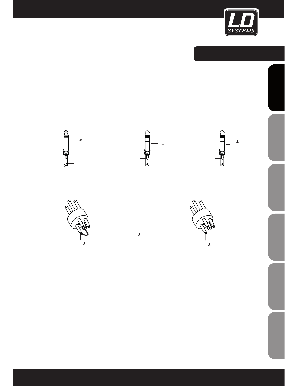
7. After connection please check the wiring to prevent any kind of accident or damage.
Please never use any kind of damaged cable and wiring.
8. Only use authorized and stable stands, brackets, shelfs, tables etc.. for installations. Please check for
adequate stability against collapse.
9. Appearance of interferences when using wireless systems.
The simultaneous use of wireless microphones and of mobile phones (if both devices are not very distant from
each other) can lead to the appearance of interferences in the microphone signal which can be heard in the
PA system.
CAUTION:
To reduce the risk of electric shock, do not remove cover (or back). No user serviceable parts inside. Refer
servicing to qualified personnel.
The lightning flash with arrowhead symbol within an equilateral triangle is intended to alert the
user to the presence of uninsulated “dangerous voltage” within the product´s enclosure that may be
of sufficient magnitude to constitute a risk to persons.
The exclamation mark within an equilateral triangle is intended to alert the user to the presence of
important operating and maintenance (servicing) instructions in the literature accompanying the
appliance.
CAUTION! HIGH VOLUME!
You will operate this transmission system for professional use. Therefore the commercial use of this equipment
is liable to the rules and regulations of the Accident Prevention & Insurance Association of your industry sector.
Adam Hall as a manufacturer is bound to inform you formally about the existence of eventual sanitary risks.
This system is able to induce an acoustic pressure of 80 db. 85 db is by law the maximum audio pressure
level which your ear can be exposed to during a work day. It was set according to the technical expertise of the
occupational medicine as a basis for the noise rating level. Higher sound levels or longer exposition times could
damage your ear. The time of exposition by higher sound pressure levels should be shortened in order to prevent
from ear damages. Here are a few reliable warning signals which show that you have exposed yourself for a too
long period to excessive sound pressure levels:
- You hear bell- or whistling sounds!
- You have the impression that you can’t hear high tones anymore!
CAUTION
RISK OF EL E C T RI C SH O CK
DO NOT O PEN

5
ITALIANO
POLSKI
ESPA OL
FRANCAISFRANCAIS FRANCAISFRANCAIS FRANCAISDEUTSCHENGLISH
FEATURES & GETTING STARTED:
The LAX6/LAX6D mixer was developed for professional applications and offers the following features:
t.*$JOQVUDIBOOFMTXJUIHPMEQMBUFE9-3DPOOFDUPSTBOECBMBODFEMJOFJOQVUTtTUFSFPJOQVUDIBOOFMTXJUICBMBODFE534KBDLTtVMUSBMPXOPJTFEJTDSFUF.*$QSFBNQTXJUI7QIBOUPNQPXFStIJHIIFBESPPNBOEEZOBNJDSBOHFtXBSNBOEOBUVSBMTPVOEJOHCBOE&2POFBDIDIBOOFMtQFBL-&%POFBDIDIBOOFMt"69SFUVSOBTBOBEEJUJPOBMJOQVUtDPOUSPMSPPNBOEQIPOFTPVUQVUTtUSBDLJOQVUTBTTJHOBCMFUPNBJONJYPVUQVUTBOEQIPOFTDPOUSPMSPPNPVUQVUTtIJHIMZQSFDJTFTFHNFOUMFWFMNFUFStEJHJUBMCJUFGGFDUTQSPDFTTPS-"9%POMZtFGGFDUTQSFTFUT-"9%POMZtFGGFDUCZQBTTGVODUJPOWJB.65&TXJUDIPSGPPUTXJUDIBWBJMBCMFPQUJPOBMMZDPOOFDUT connects to DFX FOOTSWITCH jack; LAX6D only)
GETTING STARTED
1. Before plugging in your LAX6/LAX6D mixer, make certain that the available AC voltage is suitable for your
device.
2. Make certain that the mixer is turned off before connecting it to the mains power, and set all controls to
"zero". This will avoid damage to your speakers due to loud power-on noise and high levels.
3. Always turn on the mixer first and then the power amplifier. When powering down, the sequence is reversed:
First turn off the power amplifier and then the mixer.
4. Always turn off the LAX6/LAX6D mixer before connecting cables.
5. Do not use solvents to clean the LAX6/LAX6D; use a clean, dry cloth.

6
ENGLISHDEUTSCHFRANCAIS
FRANCAISFRANCAIS FRANCAISFRANCAIS ESPA OLPOLSKIITALIANO
INSTALLATION AND CONNECTION
Now that you have familiarized yourself with the functions of the LAX6/LAX6D, you should have no trouble using
it. Nevertheless, we recommend that you read the following section carefully. It contains important information
about how to obtain the best results with your mixer.
- Before connecting mics or instruments, make certain that the channel and
MAIN MIX level knobs of the LAX6/LAX6D mixer are set to minimum (all the way to the left).
- Make certain that all external devices such as mics, power amplifiers, speakers,
effects processors, etc. are connected properly.
- When running cables, take care not to injure anyone or
damage the equipment.
4FUUIF&2DPOUSPMT)*.*%-08UPUIFNJEEMFQPTJUJPO - Set the panorama and balance knobs to the middle position.
- Adjust the input gain (TRIM) controls of the individual channels, while
speaking into each connected mic (speech or vocals) or playing the instrument, and ensure
that the peak LED of the corresponding channel comes on only occasionally. This will ensure
that there is always enough headroom and dynamic range available.
- You can shape the sound of the individual signals using the respective channel equalizer.
- Repeat this sequence of steps for all of the input channels being used, always keeping an eye on the LED
level meter (OUTPUT LEVEL) so that it does not swing too far into the red area.
AUDIO CONNECTIONS
XLR and 6.3 mm TRS sockets are available on the LAX6/LAX6D mixer for maximum flexibility. The various ways
of connecting your equipment are described below.
WIRING CONFIGURATION
The XLR and 6.3 mm TRS connectors of the LAX6/LAX6D mixer permit balanced and unbalanced connections
depending on the equipment connected. Examples for wiring your system:
INSTALLATION:

7
ITALIANO
POLSKI
ESPA OL
FRANCAISFRANCAIS FRANCAISFRANCAIS FRANCAISDEUTSCHENGLISH
CONNECTION:
-Connection via 6.3mm socket
-Connection via XLR connector
Pin3 (-)
Pin2 (+)
Pin1 ( )
(Linked to Pin1 manually, )
Pin1 ( )
Pin2 (+)
Pin3 (-)
Sleeve
Tip
+
Tip
Ring
Sleeve
+
-
Tip
Ring
Sleeve
+
Monocinch, asymmetric Stereocinch, symmetric Stereocinch, asymmetric
XLR, asymmetric XLR, symmetric

8
ENGLISHDEUTSCHFRANCAIS
FRANCAISFRANCAIS FRANCAISFRANCAIS ESPA OLPOLSKIITALIANO
1MONO CHANNELS (MIC/LINE)
The mono channels offer balanced XLR connectors for low-impedance
microphones and other low-level equipment. In addition, there are 6.3 mm
TRS jack input connectors for microphones and line level equipment (e.g.,
synthesizers, drum computers, effects processors, etc.).
Note: The MIC and LINE inputs cannot be used simultaneously on the same
channel. +48V phantom power. Both XLR inputs on the mono channels
provide +48V phantom power for condenser microphones.
2INPUT GAIN ADJUSTMENT
The input gain (TRIM) control has two different scales: one for microphones
and one for line level devices. The outer ring (0 ~ 44 dB) refers to micro-
phones, the inner one (+15 ~ -30 dB) to line level devices. Always adjust
the gain control so that the peak LED above the channel level knob lights up
only occasionally. If the LED is on constantly, this can lead to distortion.
3STEREO CHANNELSThe stereo channels are configured as stereo pairs
with 6.3 mm jack input connectors. Mono signal sources should be
connected to the left jack input connector.
ŘBAND EQUALIZER
All input channels of the LAX6/LAX6D are equipped with 3-band equalizers.
4HI
This knob is used to control the high frequencies. You can use it to add more
brilliance and presence to the corresponding signal or attenuate undesirably
loud high frequencies (boost/cut range -15 dB to +15 dB, centre frequency
12 kHz).
5MID
This knob is used to control the midrange frequencies. These are the most
important frequencies for musical instruments and the human voice (boost/
cut range -12 dB to +12 dB, centre frequency 2.5 kHz).
6LOW
This knob is used to control the low frequencies. You can use it, for example,
to boost a bass drum, bass guitar or male voice (boost/cut range -15 dB to
+15 dB, centre frequency 80 Hz).
CONTROL ELEMENTS:
LINE IN 1
BAL OR
UNBAL
LINE
MIC
+15dB -25dB
0dB 40dB
MIC 1
TRIM
RIGHT
LEFT (MONO)
LINE IN 5/6LINE IN 3/4
RIGHT
LEFT(MONO)
PEAK
0
+15
8
-
LR
0
+15
8
-
0
+15-15
0
+12-12
+15
0
-15
1
PAN
AUX
LOW
80Hz
MID
2.5kHz
HI
12kHz
EQ
POST
(PRE)
DFX
1
2
3
4
5
6
7
8
9
10

9
ITALIANO
POLSKI
ESPA OL
FRANCAISFRANCAIS FRANCAISFRANCAIS FRANCAISDEUTSCHENGLISH
7AUX
This control is used to adjust the level of the signal sent to the AUX path. Please note that this is a "post fader"
path, i.e., the level of the signal sent to the AUX path is influenced by the level knob of the respective channel.
With the LAX6D, it is not only possible to route the signal to an external effects processor or the like in this man-
ner, but also to the integral effects module.
8PAN
The mono channels of the LAX6/LAX6D have panorama (PAN) controls and the stereo channels have balance
(BAL) controls, both of which are used to distribute the signal to the right and left output channels.
9PEAK LED
All channels of the LAX6/LAX6D are equipped with a peak LED for monitoring the respective audio signal. If the peak LED
lights up (6 dB below the actual clipping threshold), this means that the signal is peaking and distortion may ensue.
10 LEVEL CONTROL
This knob controls the overall volume of the respective channel, i.e., the level at which the signal is sent to the main mix.
11 MAIN MIX LEVEL
This knob is used to control the level of the signal sent to the MAIN MIX and recording (TAPE OUT) outputs.
12 PHONES/CONTROL ROOM
This control is used to adjust the level of the signal sent to the
PHONES/CONTROL ROOM output.
13 LED LEVER METER
The stereo level meter (8 segments) is used to monitor the level of the signal
sent to the PHONES/CONTROL ROOM output.
14 2-TRACK PATH
When the 2TK TO CONTROL ROOM button is pushed, the 2-TRACK IN signal
is sent directly to the CONTROL ROOM output; the level is adjusted using the
PHONES/CONTROL ROOM control.. When the 2TK TO MIX MIX button is
pushed, the 2-TRACK IN signal is sent directly to the MAIN MIX output; the
level is adjusted using the MAIN MIX LEVEL control.
Note: Both buttons can also be pressed simultaneously, so that the 2-TRACK
signal is sent to both the control room output and the main mix out; the
corresponding level is adjusted using the associated controls.
CONTROL ELEMENTS:
0
+15
8
-
0
+15
8
-
0
+15
8
-
-18
-12
-24
-6
CLIP
+6
0
+12
CONTROL ROOM
PHONES/
LEVEL
MAIN MIX
MAIN MIX
CONTROL ROOM
OUTPUT LEVEL
LR
PWRPHANTOM
2TK TO
AUX RETURN
11
12
13
14
15
16
17

10
ENGLISHDEUTSCHFRANCAIS
FRANCAISFRANCAIS FRANCAISFRANCAIS ESPA OLPOLSKIITALIANO
CONTROL ELEMENTS:
15 AUX RETURN
This control is used to adjust the return level of the stereo AUX path, i.e., the signal returned to the mixer from an
external effects processor and, with the LAX6D, the signal of the internal effects module.
16 PHANTOM LED
This LED indicates that phantom power has been activated with the corresponding switch.
17 PWR LED (POWER)
This LED indicates that the mixer is on.
18 DISPLAY
This display indicates the respectively selected effects preset.
19 PRESET SELECTOR
This preset selector is used to select the desired effect. There is a total of 100 effects presets available: Echo,
vocal, plate and various effects combinations (two effects each). Once you have found the correct preset, simply
confirm the selection by pressing the preset selector.
20 PEAK/MUTE LED
If the peak LED lights up, this means that the input signal is exceeding the clipping threshold (i.e., is too strong). If
the LED is illuminated constantly, the effects module is deactivated.
21 DFX MUTE SWITCH
This switch is used to activate/deactivate the effects module.
22 STEREO AUX RETURNS
These 6.3 mm jack (TRS) sockets are primarily used to return the audio signal from an external effects processer
to the mixer (MAIN MIX). In addition, these connectors can be used as additional AUX inputs.
23 AUX SENDS
This 6.3 mm socket is used to send the AUX signal to an external effects processor or the like.

11
ITALIANO
POLSKI
ESPA OL
FRANCAISFRANCAIS FRANCAISFRANCAIS FRANCAISDEUTSCHENGLISH
CONTROL ELEMENTS:
24 PHONES
Headphones for monitoring the output signal (MAIN MIX) can be connected
to this TRS socket.
25 CONTROL ROOM OUTPUT
These 6.3 mm sockets are used to send the signal to studio monitor
speakers or a second PA system.
26 MAIN MIX OUTPUT
The MAIN MIX output signal is send to a power amplifier via these 6.3-mm
TRS sockets.The output level is controlled by the MAIN MIX LEVEL knob (-∞
to +15 dB).
TRACK IN/OUT
INPUT
The TAPE IN input provides an additional stereo input, which can be assigned
to the PHONES/CONTROL ROOM outputs (2TK TO CONTROL ROOM button
pressed) or the MAIN MIX outputs (2TK TO MAIN MIX button pressed) alternately
or simultaneously. A stereo input of this type is frequently used to connect a CD
player or the like.
OUTPUT
These cinch (RCA) jacks can be used to send the MAIN MIX output signal to a
tape deck, CD recorder or other recording device.2
STEREO
AUX RETURNS
DFX MUTE
PEAK/MUTE
PROGRAM (PUSH)
00-09 Echo
10-19 Echo+Verb
20-29 Tremolo
30-39 Plate
FUNCTION
50-59 Vocal
60-69 Rotary
70-79 Small Room
80-89 Flange+Verb
90-99 Large Hall
8
LEFT(MONO)
RIGHT
AUX SENDS
PHONES
OUTPUT
CONTROL ROOM
MAIN MIX OUTPUT
R
R
L
L
2-TRACK IN/OUT
TAPE OUT
TAPE IN
R
L
40-49 Chorus
18
20
19
21
23
22
23
24
25
26

12
ENGLISHDEUTSCHFRANCAIS
FRANCAISFRANCAIS FRANCAISFRANCAIS ESPA OLPOLSKIITALIANO
CONTROL ELEMENTS:
1 PHANTOM SWITCH
This switch activates the +48V phantom power for the two XLR microphone inputs. Important: Never connect
microphones when the phantom power is already on.
2 POWER SWITCH
This switch is used to turn the mixer ON or OFF.
3 AC INPUT
This socket is used to connect the external power adapter.
POWER
ON OFF
PH AN TO M
AC INP UT
CAUTION
RISK OF ELECTRIC SHOCK
DO NOT OPEN
CAUTION:
REPLACE WITH THE SAME TYPE FUSE AND RATING
DISCONNECT SUPPLY CORD BEFORE CHANGINGFUSE
WARNING: SHOCK HAZARD
AVIS: RISQUE DE CHOC ELECTRIQUE
- DO NOT OPEN
- NE PAS OUVRIR
LAIRESLEDOM
12
3

13
ITALIANO
POLSKI
ESPA OL
FRANCAISFRANCAIS FRANCAISFRANCAIS FRANCAISDEUTSCHENGLISH
Unbalanced
Balanced
In-line connections
The LAX16D power mixer provides XLR and 6.3 mm TRS connectors for connection of most professional audio
equipment. Examples are depicted below:
BLOCK DIAGRAM
Tip
Rin g
Sl eeve
Tip
Ring
Sleeve
Tip
Sl eeve
Tip
Sleeve
Tip
Sl eeve
Cent er
Cent er
Centre
Sc reen
Sc reen
Sc reen
1
2
3
Tip
Rin g
Sl eeve
1
2
3
1
2
3
TIP SL EEV E
TIP SL EEVE
TIP RING SL EEVE
TIP RING SL EEVE
1 2
3
2 1
3
2 1
3
Tip
Rin g
Sl eeve
1
2
3
Tip
Sl eeve
1
2
3
TIP RING SL EEVE
TIP SL EEV E
1 2
3
1 2
3
SL EEVE TI P
SL EE VE RI NG T I P
Tip
Ring
Sleeve
Tip
Ring
Sleeve
Tip
Ring
Sleeve
1
2
3
1
2
3
1
2
3
TIP RING SLE EVE S LEEVE R INGT IP
TIP RING SLE EVE
21
3
1 2
3
1 2
3
Tip
Ring
Sleeve
Tip
Ring
Sleeve
Tip
Ring
Sleeve
1
2
3
1
2
3
1
2
3
TIP RING S LEE VE SL EEVE RING TIP
TIPRING SL EEVE
21
3
1 2
3
1 2
3
U b l d

14
ENGLISHDEUTSCHFRANCAIS
FRANCAISFRANCAIS FRANCAISFRANCAIS ESPA OLPOLSKIITALIANO
PRESET LIST:
No. PRESET DESCRIPTION PARAMETER
00 - 09 Echo The input signal is sent to the
output with a time delay
Delay time: 145 ms - 205 ms
10 - 19 Echo & reverb Echo with room effect (hall) Delay time: 208 ms - 650 ms
Decay time 1.7 s - 2.1 s
20 - 29 Tremolo Amplitude modulation of the
signal
Rate: 0.6 Hz - 5 Hz
30 - 39 Plate Hall effect: Simulation of a
classic vocal plate reverb effect
(adds brightness)
Decay time: 0.9 s - 3.6 s
40 - 49 Chorus Creates the illusion of multiple
instruments (voices) on the
basis of a single signal
Rate: 0.92 Hz - 1.72 Hz
50 - 59 Vocal Hall effect: Simulation of a
small room with a short decay
time
Rev. decay time: 0.8 s - 0.9 s
Pre-delay: 0 ms - 45 ms
60 - 69 Rotary Simulation of typical rotary
speaker effect incl. bass box
Modulation depth:
20 % - 80 %
70 - 79 Small room Hall effect: Simulation of a
bright studio room effect
Decay time 0.7 s - 2.1 s
Pre-delay: 20 ms - 45 ms
80 - 89 Flanger &
reverb
Combination of a modulated
delay effect plus hall
Decay time: 1.5 s - 2.9 s
Rate: 0.8 Hz - 2.52 Hz
90 - 99 Large hall Hall effect: Simulation of a large
room 3.6-5.4 s.
Pre-delay: 23 ms - 55 ms

15
ITALIANO
POLSKI
ESPA OL
FRANCAISFRANCAIS FRANCAISFRANCAIS FRANCAISDEUTSCHENGLISH
SPECIFICATIONS:
MONO CHANNELS
Microphone input:
electronically balanced, separate inputs
'SFRVFODZSBOHF)[L)[E#5)%/!E#VL)[Gain: 0 dB - 40 dB (MIC)
S/N Ratio: 102 dB
Line input: electronically balanced
'SFRVFODZSBOHF)[L)[E#5)%/!E#VL)[(BJOE#VE#V-*/&STEREO CHANNELS
Line input: unbalanced
'SFRVFODZSBOHF)[L)[E#5)%/!E#VL)[IMPEDANCE
Microphone input: 3.6 kohms
All other inputs: 10 kohms or higher
Tape out: 1 kohm
All other outputs: 120 ohms
EQUALIZER
)JTIFMWJOHE#!L)[.JESBOHFCFMME#!L)[#BTTTIFMWJOHE#!)[MAIN MIX SECTION
Noise (bus noise): Level adjusters 0 dB, channels
NVUFEE#SSFGE#VLevel adjusters 0 dB, all input channels activated
VOJUZHBJOE#SSFGE#V.BYPVUQVUMFWFME#VNNKBDLVOCBMBODFE"69SFUVSOTHBJO0''E#"69TFOETNBYPVUQVUMFWFME#VPOWER SUPPLY
(AC adapter)
Mains voltage:
USA/Canada 100 – 120 V, ~60 Hz
Europe 210 – 230 V, ~50 Hz
Great Britain/Australia 240 V, ~50 Hz
Power consumption: 10 W
PHYSICAL SPECIFICATIONS
Dimensions (WxDxH): 285 x180 x 65/45 mm; weight:
2.0 kg without adapter
Our products are subject to a continuous process
of development and improvement. Thus technical
characteristics are subject to change without notice.

16
ENGLISHDEUTSCHFRANCAIS
FRANCAISFRANCAIS FRANCAISFRANCAIS ESPA OLPOLSKIITALIANO
LIMITED WARRANTY
This Limited Warranty applies to the Adam Hall, LD Systems, Defender, Palmer and Eminence branded products.
The statutory warranty rights towards the seller are not affected by this guarantee. In fact, it justifies, additional
independent warranty claims towards Adam Hall.
Adam Hall warrants that the Adam Hall product you have purchased from Adam Hall or from an Adam Hall autho-
rized reseller is free from defects in materials or workmanship under normal use for a period of 2 or 5 years from
the date of purchase.
The Limited Warranty Period starts on the date of purchase. In order to receive warranty services you are required
to provide proof of the purchase date. Your dated sales or delivery receipt, showing the date of purchase, is your
proof of the purchase date. Should products of the brands named above be in need of repair within the limited war-
ranty period, you are entitled to warranty services according to the terms and conditions stated in this document.
This Limited Warranty extends only to the original purchaser of this Adam Hall branded product and is not trans-
ferable to anyone who obtains ownership of the Adam Hall branded product from the original purchaser. During
the Limited Warranty Period, Adam Hall will repair or replace the defective component parts or the product. All
component parts or hardware products removed under this Limited Warranty become the property of Adam Hall.
In the unlikely event that your Adam Hall product has a recurring failure, Adam Hall, at its discretion, may elect to
provide you with a replacement unit of Adam Hall´s choice that is at least equivalent to your Adam Hall branded
product in hardware performance.
Adam Hall does not warrant that the operation of this product will be uninterrupted or error-free. Adam Hall is not
responsible for damage that occurs as a result of your failure to follow the instructions included with the Adam
Hall branded product.
This Limited Warranty does not apply,
- to wear parts (e.g. accumulator)
- to any product from which the serial number has been removed or that has been damaged or rendered defec
tive as the result of an accident
- in case of, misuse, abuse, or other external causes
- by operation outside the usage parameters stated in the user´s documentation shipped with the
product
- by use of spare parts not manufactured or sold by Adam Hall
- by modification or service by anyone other than Adam Hall
These terms and conditions constitute the complete and exclusive warranty agreement between you and Adam
Hall regarding the Adam Hall branded product you have purchased.
MANUFACTURER´S DECLARATIONS:

17
ITALIANO
POLSKI
ESPA OL
FRANCAISFRANCAIS FRANCAISFRANCAIS FRANCAISDEUTSCHENGLISH
LIMITATION OF LIABILITY
If your Adam Hall branded hardware product fails to work as warranted above, your sole and exclusive remedy
shall be repair or replacement. Adam Halls’ maximum liability under this limited warranty is expressly limited
to the lesser of the price you have paid for the product or the cost of repair or replacement of any hardware
components that malfunction in conditions of normal use.
Adam Hall is not liable for any damages caused by the product or the failure of the product, including any lost
profits or savings or special, incidental, or consequential damages. Adam Hall is not liable for any claim made by
a third party or made by you for a third party.
This limitation of liability applies whether damages are sought, or claims are made, under this Limited Warranty
or as a tort claim (including negligence and strict product liability), a contract claim, or any other claim. This limi-
tation of liability cannot be waived or amended by any person. This limitation of liability will be effective even if
you have advised Adam Hall of an authorized representative of Adam Hall of the possibility of any such damages.
This limitation of liability however, will not apply to claims for personal injury.
This Limited Warranty gives you specific legal rights. You may also have other rights that may vary from state to
state or from country to country. You are advised to consult applicable state or country laws for a full determina-
tion of your rights.
3&26&45*/(WARRANTY-SERVICE
To request warranty service for the product, contact Adam Hall or the Adam Hall authorized reseller from which
you purchased the product.
EG-DECLARATION OF CONFIRMITY
These products meet the essential requirements as well as the further standards of the EU Directives 199/5/EU,
89/336/EU.

18
ENGLISHDEUTSCHFRANCAIS
FRANCAISFRANCAIS FRANCAISFRANCAIS ESPA OLPOLSKIITALIANO
WEEE-DECLARATION
Your LD-Systems product was developed and manufactured with high quality materials and components wich
can be recycled and/or reused. This symbol indicates that electrical and electronic equipment must be disposed
of separately from normal waste at the end of its operational lifetime.
Please dispose of this product by bringing it to your local collection point or recycling centre for such equipment.
This will help to protect the environment in which we all live.
BATTERIES AND ACCUMULATORS
The supplied batteries or rechargeable batteries can be recycled. Please dispose of them as special waste or return
them to your specialist dealer. In order to protect the environment, only dispose exhausted batteries.
Adam Hall GmbH, all rights reserved. The technical data and the functional product characteristics can be subject
to modifications. The photocopying, the translation, and all other forms of copying of fragments or of the integral-
ity of this user’s manual is prohibited.

19
ITALIANO
POLSKI
ESPA OL
FRANCAISFRANCAIS FRANCAISFRANCAIS FRANCAISDEUTSCHENGLISH
NOTES:
NOTES:

20
ENGLISHDEUTSCHFRANCAIS
FRANCAISFRANCAIS FRANCAISFRANCAIS ESPA OLPOLSKIITALIANO
Mit einem Produkt von LD Systems haben Sie die richtige Wahl getroffen!
%JFTFT(FSÊUXVSEFVOUFSIPIFO2VBMJUÊUTBOGPSEFSVOHFOFOUXJDLFMUVOEHFGFSUJHUVNWJFMF+BISFFJOFOSFJCVOHT-
losen Betrieb zu gewährleisten. Dafür steht LD Systems mit seinem Namen und der langjährigen Erfahrung als
Hersteller hochwertiger Audioprodukte.
Bitte lesen Sie diese Bedienungsanleitung sorgfältig, damit Sie Ihren neuen Verstärker von LD Systems schnell
optimal einsetzen können.
Weitere Informationen zu Produkten von LD Systems erhalten Sie auf unserer Internet-Seite WWW.LD-SYSTEMS.COM.
This manual suits for next models
1
Table of contents
Languages:
Other LD Music Mixer manuals
Popular Music Mixer manuals by other brands

Mackie
Mackie Mackie Control Universal Pro quick start guide

PRESONUS
PRESONUS StudioLive AR-Series owner's manual

Mackie
Mackie X.200 Frequently asked questions

STK Professional Audio
STK Professional Audio VM6S-DRVH owner's manual

Reloop
Reloop RMX-40 DSP Operation manual

Studer
Studer OnAir 3000 Service instructions