LD LD LAX20D User manual

LD LAX20D
20 ChanneL Mixer with DSP
USer´S ManUaL
BeDienUnGSanLeitUnG
MODe D´eMPLOi
inStrUKCJa OBSŁUGi
MIXING CONSOLE

ENGLISHDEUTSCHFRANCAIS
FRANCAISFRANCAIS FRANCAISFRANCAIS ESPAÑOLPOLSKI
Thank you for choosing LD-Systems!
We have designed this product to operate reliably over many years. Therefore LD-Systems guarantees for high
quality products with its name and many years of experience as a producer.
Please, take a few moments to read these instructions carefully, as we want you to enjoy your new LD-Systems
products quickly and to the fullest.
For information about LD-Systems check out our website WWW.LD-SYSTEMS.COM

3
LD LAX20D
20 ChanneL Mixer with DSP
MIXING CONSOLE
ENGLISHDEUTSCHFRANCAIS
FRANCAISFRANCAIS FRANCAISFRANCAIS ESPAÑOLPOLSKI

ENGLISHDEUTSCHFRANCAIS
FRANCAISFRANCAIS FRANCAISFRANCAIS ESPAÑOLPOLSKI
PREVENTIVE MeaSUreS:
1. Please read the attached safety instructions as well as the following instructions carefully.
2. Please keep all the instructions.
3. Please use the device only as intended.
4. Please respect the valid waste management rules. Please deliver the packaging divided into plastic and
paper/ cardboard to the recycling management.
5. Please refer all servicing to qualified personel only if the device is damaged, exposed to liquid/rain or if it does
not operate normally.
6. Please, do not expose to any kind of heat such as ovens, radiators, or any other devices (incl. amplifiers).
Please check for enough distance between amplifiers and walls, racks, etc. to prevent overheating.
7. After connection please check the wiring to prevent any kind of accident or damage.
Please never use any kind of damaged cable and wiring.
8. Only use authorized and stable stands, brackets, shelfs, tables etc.. for installations. Please check for
adequate stability against collapse.
CAUTION:
To reduce the risk of electric shock, do not remove cover (or back). No user serviceable parts inside. Refer
servicing to qualified personnel.
The lightning flash with arrowhead symbol within an equilateral triangle is intended to alert the
user to the presence of uninsulated “dangerous voltage” within the product´s enclosure that may be
of sufficient magnitude to constitute a risk to persons.
The exclamation mark within an equilateral triangle is intended to alert the user to the presence of
important operating and maintenance (servicing) instructions in the literature accompanying the
appliance.
CAUTION
RISK OF ELECTRIC SHOCK
DO NOT O PEN

5
FEATURES & GettinG STARTED:
FEATURES
The LDLAX20D mixing console is designed for professional application.
It will provide the following features:
• MICinputchannelswithgoldplatedXLRandbalancedLINEinputs
• StereoinputchannelswithbalancedTRSjacks
• Ultra-lownoisediscreteMICpre-ampswith+48VPhantompower
• Veryhighheadroomofferingmoredynamicrange
• Insertoneachofmonoinputchannels
• SwitchableLow-cutlteroneachmonochannel
• +4dBu/-10dBVselectoroneachmonostereochannel
• Warm,natural4-bandxedfrequencyEQoneachstereochannel
• 3-bandEQwithmidsweep(100Hz~8KHz)oneachmonochannel
• PeakLEDoneachchannel
• Mute/ALT3-4,SOLOfunctiononeachchannel
• 2AUXReturnsforadditionalfunctionality
• ControlRoomandPhoneoutputs
• 2-TrackinputsassignabletoMainMix,ControlRoom/Phonesoutputs
• Highlyaccurate12-segmentLEDmeters
• 24bitdigitaleffectprocessor
• Upto100presets
• Effecton/offbymeansofMUTEswitchorafootswitchconnectedtotheDFXFOOTSWITCHjack.
GETTinG STARTEd
Please check the AC voltage available in your country before connecting your LD LAX20D to the AC socket.
BesurethatthemainpowerswitchisturnedoffbeforeconnectingthemixertotheACsocket.Also,youshould
make sure that all input and output controls are turned down. This will avoid damage to your speakers and avoid
excessive noise.
BeforeturningontheLDLAX20Dyoushallconnectittoapoweramplierandturn-onthemixerBEFOREthe
power amplifier. Once you have finished your working session you shall turn the mixer off AFTER the power
amplifier is turned off.
BeforedisconnectingtheLDLAX20Dalwaysturn-offthepowerswitch.
Do not use solvents to clean your LD LAX20D . A dry and clean cloth will be OK.
ENGLISHDEUTSCHFRANCAIS
FRANCAISFRANCAIS FRANCAISFRANCAIS ESPAÑOLPOLSKI

CONTROL eLeMentS:
1THE MONO MIC/LINE CHANNELS
You can connect balanced, low impedance microphones or a low
level signal to the XLR socket. On the 1/4 “ line jack you can connect
either a microphone or a line level instrument such as synthesizers,
drum machines, effect processors or any other line level signal.
Note: You shall never connect an unbalanced microphone to the XLR
socket if you do not want to damage both the microphone and mixer.
Also, it is not possible to simultaneously use both the MIC & LINE
inputs on the same channel, use only one of them for the appropriate
source.
2INPUT LEVEL SETTING
This control is provided with 2 different indication rings: one is for
the microphone and the other for the line level. When you use a
microphoneyoushallreadtheOUTSIDEring(0~40dB),whenyou
use a line level instrument you shall set this control in a way that the
peak LED will blink also occasionally in order to avoid distortion on
the input channel.
3LOW CUT SWITCH
Bypressingthisbuttonyouwillactivatea75Hzlowfrequencylter
withaslopeof18dBperoctave.Youcanusethisfeaturetoreduce
the hum noise caused by the mains power supply, or the stage
rumble while using a microphone.
4STEREO INPUTS
They are organized in stereo pair and provided with 1/4 ‘’ TRS so-
ckets. Use the left input if connect a mono input signal to the STEREO
INPUT.
5+4dBu/-10dBV
These switches select the input sensitivity of the line inputs on the
stereochannels.+4dBuissuitableforprofessionalaudiodevices,
-10dBVissuitableforgeneralHI-FIdevices.Ifyouarenotsurewhich
settingtouse,tryatrst+4dBu,ifthevolumelevelistoolowchange
itto-10dBV.
6AUX SENDS
These 1/4“ sockets are used to send out the signal from the AUX bus
to external device such as effect equipments. They also can be used
as monitoring outputs by connecting a power amplifier and monitor
speaker.
7PHONES
This socket will send out the mix signal to a pair of headphones.
1
2
3
4
6
5
7
LINE IN 1
BAL OR
UNBAL
LINE
MIC
+15dB -25dB
0dB 40dB
LOW CUT
75Hz 18dB/Oct
MIC 1
LINE IN 19/20
+4dBu
-10dBV
LEFT(MONO)
RIGHT
AUX SENDS
1
PHONE
2
ENGLISHDEUTSCHFRANCAIS
FRANCAISFRANCAIS FRANCAISFRANCAIS ESPAÑOLPOLSKI

7
8 EQUALIZER
Themonoinputchannelsareequippedwith3-bandEQwithhalf-
parametric MID control.
EQ:HIband,MIDbandandLOWband.
And the stereo channels are equipped with 4-band fixed frequency.
EQ:HIband,HI-MIDband,MID-LOWbandandLOWband.Allbands
provideupto15dBboostorcut.
9 HI
This is the treble control. You can use it to get rid of high frequency of
thehumanvoice.Thegainrangegoesfrom-15dBto+15dBwitha
center frequency of 12 kHz.
10 MID
Thisisthemidrangecontrol.Itprovides15dBboostorcut,atat
thecenterdetentandtheFREQknobsetsthecenterfrequency,the
adjustable range goes from 100Hz to 8 KHz. It can affect most funda-
mental frequencies off all musical instruments and human voice.
11 HI-MID
Thiscontrolprovidesyouupto15dBboostorcutat3kHz.Itisuseful
to control voice.
12 MID-LOW
Thecontrolprovidesyouupto15dBboostorcutat500Hz.
13 LOW
This is the bass control. It is used to boost male voice, kick-drum
orbassguitar.Thegainrangegoesfrom-15dBto+15dBandthe
center frequency is 80 Hz.
14 AUX SENDS CONTROL
These two controls are used to adjust the level of signal sent to AUX
bus 1 & 2, and this adjustment doesn’t effect the main mix output
signal at all.
AUX1 can be configured as PRE/POST fader via the PRE/POST switch.
Up for POST fader, the signal is sent out after the channel fader and
will be affected by the channel fader. Down for PRE fader, the signal
is sent out before the channel fader and will not be affected by the
channel fader. AUX2 is configured as PRE fader through internal
modification.
CONTROL eLeMentS:
10
dB
-5
-10
-15
-20
-30
-40
-60
0
5
10
dB
-5
-10
-15
-20
-30
-40
-60
0
5
MUTE /
ALT 3-4
SOLO
MUTE /
ALT 3-4
SOLO
45/6
HI
12kHz
EQ
+15
0
-15
HI
12kHz
EQ
+15
0
-15
PAN
L R L R
LOW
80Hz
0
+15-15
LOW
80Hz
0
+15-15
MID
0
+15-15
HI-MID
3kHz
0
+15-15
FREQ
100Hz 8kHz
800
MID-LO
500Hz
+15-15
00
AUX
1
PRE
PO ST
0
+15
8
-
AUX
1
PRE
PO ST
0
+15
8
-
2
POST
(PRE)
8
-
0
+15
DFX
2
POST
(PRE)
8
-
0
+15
DFX
BAL
PEAK PEAK
8
10
11
12
14
17
9
13
15
16
18
ENGLISHDEUTSCHFRANCAIS
FRANCAISFRANCAIS FRANCAISFRANCAIS ESPAÑOLPOLSKI

CONTROL eLeMentS:
15 PAN/BAL CONTROL
PANORAMAandBALANCEcontrol.
You can adjust the stereo image of the signal via this control. Keep
this control in center position and your signal will be positioned in
the middle of stage. Turn this control fully counter clockwise and the
signal will be present only on the left speaker and vice-versa.
16 MUTE/ALT 3-4 SWITCH
Each channel is equipped with the MUTE/ALT 3-4 switch. This switch
is used to route the channel signal to ALT 3-4 output instead of the
main mix.
17 SOLO SWITCH
When pressing this button, the SOLO signal will replace other signals
and reach to the CONTROL ROOM/PHONES. Usually use the SOLO
function to preview each channel signal before they are let into the
mix.
Itisusefultosetaninstrument’sinputlevelandEQ,andyoucan
“solo” any channel that you want to. However, the SOLO switch never
affects any mix other than the PHONES/CONTROL ROOM mix.
18 FADER
This control will adjust the overall level of this channel and set the
amount of signal sent to the main output.
ENGLISHDEUTSCHFRANCAIS
FRANCAISFRANCAIS FRANCAISFRANCAIS ESPAÑOLPOLSKI

9
CONTROL eLeMentS:
19 TRACK IN/OUT
-TAPE IN
Use the Tape input to connect a Tape Recorder or DAT. You can assign the signal coming from the Tape Recorder
either to CONTROL ROOM/PHONES output using the 2TK IN button on the front panel or to the MAIN MIX output
using the 2TK TO MAIN MIX button.
- TAPE OUT
These RCA sockets will route the main mix into a tape recorder.
- 2TK IN CONTROL
This control is used to adjust the level of 2TK IN signal, which can be varied from - ∞ to MAX.
20 STEREO AUX RETURNS
Each channel is equipped with the MUTE/ALT 3-4 switch. This switch is used to route the channel signal to ALT
3-4 output instead of the main mix.
21 AUX RETURN CONTROL
When pressing this button, the SOLO signal will replace other signals and reach to the CONTROL ROOM/PHONES.
Usually use the SOLO function to preview each channel signal before they are let into the mix.
Itisusefultosetaninstrument’sinputlevelandEQ,andyoucan“solo”anychannelthatyouwantto.However,
the SOLO switch never affects any mix other than the PHONES/CONTROL ROOM mix.
22 EFX TO AUX 1
This switch will route the signal that is present at the AUX RETURN 2 jacks to AUX 1 output so that the effects
can be heard in the monitor mix.
23 AUX SENDS CONTROL
BothswitchesareusedtodeterminethemasterAUXSENDSlevels.Theadjustablerangeisfrom–∞to+15dB.
Whentheeffectunitconnectedtomixerhasnoinputgaincontrol,youcangetafurther+15dBgainavailable
from these AUX SENDS outputs.
24 OUTPUT LEVEL LED DISPLAY
This stereo 12 segments LED meter will indicate the level of the overall output signal.
LEFT
LEFT(MONO)
RIGHT
STEREO AUX RETURNS
2
1
RIGHT
TAPE IN TAPE OUT
2-TRACK IN/OUT
MAX
2TK IN
R
L
20 19
ENGLISHDEUTSCHFRANCAIS
FRANCAISFRANCAIS FRANCAISFRANCAIS ESPAÑOLPOLSKI

CONTROL eLeMentS:
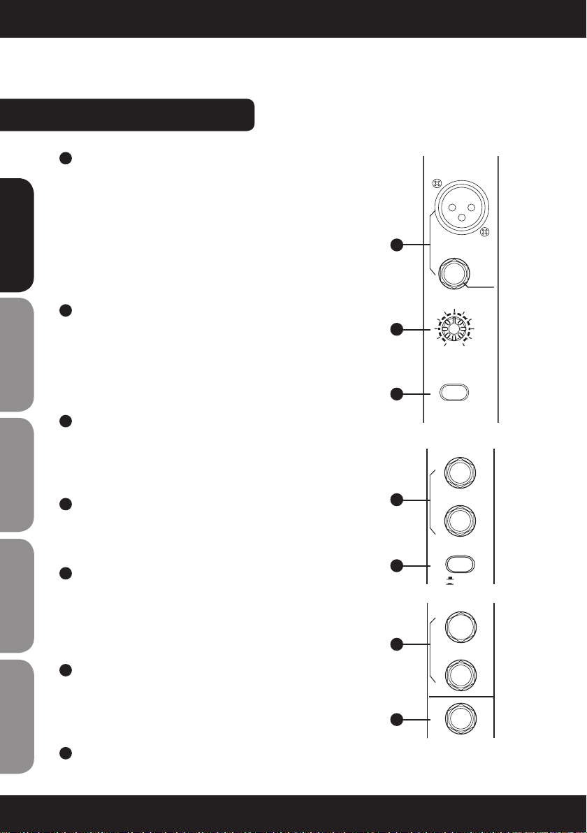
25 SOLO MODE SWITCH & SOLO ACTIVE LED INDI-
CATOR
This button provides two modes: up for PFL (Pre-
Fader-Listen) mode, down for AFL (After-Fader-Listen)
mode. Engage the button, the output signal of soloed
channel will be sent out after its channel fader.
Release the button to enter into PFL mode, the signal
of soloed channel will be sent out before its channel
FaderandnotaffectedbythePAN/BALandfadercon-
trol. When the solo mode is engaged, the LED beside
it will light up.
Note: The SOLO MODE switch will not be usable
unless one or more channel SOLO switches have been
pressed down.
26 ALT 3-4 CONTROL
This fader is used to adjust the level of the ALT output,
andtheadjustrangeisfrom-∞+10dB,thisisano-
ther way to offer you extra independent stereo sub mix
with its own level adjustment control.
27 MAIN MIX LEVEL
These two faders set the amount of signal sent both to
the main Output and the Tape Output.
28 2TK TO MAIN MIX
This control will adjust the overall level of this channel
and set the amount of signal sent to the main output.
29 ALT 3-4 TO MAIN MIX
This control will adjust the overall level of this channel
and set the amount of signal sent to the main output.
30 CONTROL ROOM SOURCE
You can choose to monitor any combination of MAIN
MIX, ALT 3-4 and 2TK IN via these matrix switches.
The ALT 3-4 is additional stereo mix bus, 2TK IN is the
stereo signal coming from the TAPE IN jacks. These
stereo signals will be delivered to the PHONES/CON-
TROL ROOM by engaging these switches.
Note: when the channel’s SOLO switch was engaged,
then the SOLO signal will replace other signals, and
also be sent to the CONTROL ROOM / PHONES.
AUX RTN 1
8
-
0
+15
2
AUX RTN 2
8
-
0
+15
EFX TO AUX 1
AUX SENDS
2
8
-
0
+15
SOLO
ACTIVE
SOLO MODE
LEVEL
SET
PFL
AFL
-2
0
-4
-7
-10
-20
+2
-30
OUTPUT LEVEL
LR
ALT 3-4
2TK
CLIP
+10
+7
+4
2TK IN
ASSIGN
TO MIX
MAIN MIX
LEVEL
10
dB
-5
-10
-15
-20
-30
-40
-60
0
5
10
dB
-5
-10
-15
-20
-30
-40
-60
0
5
10
dB
-5
-10
-15
-20
-30
-40
-60
0
5
ALT 3-4
1
PWRPHANTOM
MAIN MIX
ALT 3-4
CTR ROOM
SOURCE
+15
0
PHONES
CONTROL ROOM
10
+15
8
-
RIGHT
LEFT
DFX MUTE
PEAK/MUTE
PROGRAM (PUSH)
00-09 Echo
10-19 Echo +Verb
20-29 Tremolo
30-39 Plate
40-49 Chorus
FUNCTION
50-59 Vocal
60-69 Rotary
70-79 Small Room
80-89 Flange+Verb
90-99 Large Hall
DFX
8
-
88
21
22
23
24
25
26
27
28
29
30
31
32
33
ENGLISHDEUTSCHFRANCAIS
FRANCAISFRANCAIS FRANCAISFRANCAIS ESPAÑOLPOLSKI

11
CONTROL eLeMentS:
31 POWER LED
This LED indicates when the power is on.
32 PHANTOM LED
This LED indicates when the phantom power is
switched on.
33 PHONE/CONTROL ROOM CONTROL
This control will adjust the overall level of this channel
and set the amount of signal sent to the main output
24 BIT DIGITAL EFFECTS
34 DFX MUTE SWITCH
This switch is used to activate/deactivate the effect
feature. Sometimes, you can also use the DFX
FOOTSWITCH for a more convenient operation.
35 DISPLAY
Displays the selected preset.
36 PRESETS SELECTOR
Adjust this knob to select the right effect you wish to
perform. There is a total of 100 presets available: Echo,
Vocal,Plateandversatiletwo-effectcombination.
When you found the right preset, push the knob to
confirm your selection.
37 PEAK LED
This LED lights up when the input signal is too strong.
In case of the digital effect module being muted, this
LED also lights up.
35
37 34
36
DFX MUTE
PEAK/MUTE
PROGRAM (PUSH)
00-09 Echo
10-19 Echo +Verb
20-29 Tremolo
30-39 Plate
40-49 Chorus
FUNCTION
50-59 Vocal
60-69 Rotary
70-79 Small Room
80-89 Flange+Verb
90-99 Large Hall
88
ENGLISHDEUTSCHFRANCAIS
FRANCAISFRANCAIS FRANCAISFRANCAIS ESPAÑOLPOLSKI

REAR PaneL:
38 MONO CHANNEL INSERT
Insert sockets are provided for all mono MIC channels. It can allow you to patch external signal processing
devices into signal path via a TRS connector, the signal will be taken out after the input gain control (TRIM), and
sent to an external processor such as a compressor- limiter, then returned into the same channel immediately
beforetheEQsection.
Note: Usually, insert connections require a special stereo-splitting Y-cord to be connected, know as TRS connec-
tor (Tip Send/Ring return).
39 ALT OUTPUT
These1/4‘’socketsareunbalancedoutputs.Theyarecapableofdelivering+22dBu.ThesignalleveltotheALT
OUTPUT is adjusted by ALT 3-4 rotary on the front panel.
40 CTRL ROOM OUTPUT
These 1/4’’ sockets are used to send the control room signal to the studio monitor speakers or a second
set of PA.
41 MAIN MIX OUTPUT
The stereo output is supplied both with XLR and 1/4‘’ TRS sockets, which are used to send the audio signal to an
amplier.Throughthemainmixlevelcontrol,youcanadjusttheoutputlevelfrom-∞to+10dB.
42 FOOT SW
This socket is used to connect external footswitch for a convenient operation, it will activate/deactivate the DSP
module in this unit and function same as DFX MUTE switch.
43 POWER ON/OFF SWITCH
This switch is used to turn the main power ON and OFF.
44 PHANTOM ON/OFF SWITCH
Thisswitchwillapply+48VoltPhantomonlytothe8XLRmicrophoneinputs.Neverconnectmicrophoneswhen
the Phantom power is already on.
45 AC INPUT
It is used to connect to main power.
POWER
ON OFF
PHANTOM
INSERT
INSERT
INSERT
INSERT
LEFT
RIGHT
MAIN MIX OUTPUT(BAL/UNBAL)
R
ALT OUTPUTCTRL ROOM
OUTPUT RIGHT(4)
LEFTRIGHT
78 5
6
L
LEFT(3)
CAUTION
RISK OF ELECTRIC SHOCK
DO NOT OPEN
CAUTION:
REPLACE WITH THE SA ME TYPE FUSE AND RATING
DISCON NECT SUPPLY CORD BEF ORE CHA NGING FU SE
WARNING: SHOCK HAZARD
AVIS: RISQUE DE CHOC ELECTRIQUE
- DO NOT OPEN
- NE PAS OUVRIR
SERIAL
MODEL
Apparaten skall anslutas
till jordat uttag nar den
ansluts till ett natverk
INSERT
INSERT
INSERT
INSERT
34 12
INSERT
INSERT
INSERT
INSERT
1112 9
10
AC INPUT
100-240V 50/60Hzǡ
POWER CONSUMPTION: 40W
Fuse:T1.6AL 250V
43 45 41 40 39 38
44 42
ENGLISHDEUTSCHFRANCAIS
FRANCAISFRANCAIS FRANCAISFRANCAIS ESPAÑOLPOLSKI

13
INSTALLATION & COnneCtiOn:
Ok, you have got to this point and you are now in the position to successfully operate your XM-20/20D, however,
we advise you to read carefully the following section to be the real master of your own mixer. Not paying enough
attention to the input signal level, to the routing of the signal and the assignment of the signal will result in
unwanted distortion, a corrupted signal or no sound at all. So you should follow these procedures for every single
channel:
•Beforeconnectingmicsorinstruments,makesurethatthepowerofallyoursystemscomponentsincluding
the mixer is turned off. Also, make sure that all input and output controls of your mixer are turned down. This
will avoid damage to your speakers and avoid excessive noise.
•Properlyconnectallexternaldevicessuchasmics,powerampliers,speakers,effectsprocessoretc.
Note: the power amplifier or powered monitors shall be turned on after the mixer and turned off before the
mixer
•Settheoutputlevelofyourmixerortheconnectedpoweramplieratnomorethan75%.
•SettheCONTROLROOM/PHONElevelatmorethan50%.
•PositionHI,MIDandLOWEQcontrolsonmiddleposition.
•Positionpanoramic(PAN/BAL)controloncenterposition.
•Whilespeakingintothemic(orplayingtheinstrument),adjustthechannelLevelcontrolsothatthechannel
PEAK LED will blink occasionally, in this way you will maintain good headroom and idea dynamic range.
•Youcanshapethetoneofeachchannelbyadjustingtheequalizercontrolsasdesired.
•Nowrepeatthesamesequenceforallotherinputchannels.ThemainLEDcouldmoveupintothered
section, in this case you can adjust the overall output level through the MAIN MIX control.
•ForLAX20D,youcanselectdesiredDSPsoundeffectsviaPRESETcontrols.
AUDIO CONNECTION
BothXLRand1/4’’TRSconnectorsareavailableontheunit.Inthiswayyoucaninterfacetheunitinseveral
different ways without experiencing any noise or signal loss. You can use the unit with single instruments using
the mixer’s main insert or on “in-line” between a mixing console’s output and a power amplifier.
WIRING CONFIGURATION
Either the 1/4‘’ TRS phone jack or XLR connector can be wired in balanced and unbalanced modes, which will
be determined by the actual application status, please wire your system as the following wiring example:
ENGLISHDEUTSCHFRANCAIS
FRANCAISFRANCAIS FRANCAISFRANCAIS ESPAÑOLPOLSKI

INSTALLATION & COnneCtiOn:
Sleeve
Tip
+
Tip
Ring
Sleeve
+
-
Tip
Ring
Sleeve
+
Pin3 (-)
Pin2 (+)
Pin1 ( )
(Linked to Pin1 manually, )
Pin1 ( )
Pin2 (+)
Pin3 (-)
Tip
Ring
Sleeve
Tip
Ring
Sleeve
Tip
Ring
Sleeve
1
2
3
1
2
3
1
2
3
TIP RING SLEEVE SLEEVE RING TIP
TIP RING SLEEVE
21
3
1 2
3
12
3
Tip
Ring
Sleeve
Tip
Ring
Sleeve
Tip
Sleeve
Tip
Sleeve
Tip
Sleeve
Cent er
Cent er
Centre
Screen
Screen
Screen
1
2
3
Tip
Ring
Sleeve
1
2
3
1
2
3
TIP SLEEVE
TIP SLEEVE
TIP RING SLEEVE
TIP RING SLEEVE
12
3
2 1
3
2 1
3
Tip
Ring
Sleeve
1
2
3
Tip
Sleeve
1
2
3
TIP RING SLEEVE
TIP SLEEVE
1 2
3
12
3
SLEEVE TIP
SLEEVE RING TIP
IN – LINE CONNECTION
For these applications the unit provides 1/4’’ TRS and XLR connectors to easily interface with most professional
audio devices. Follow the configuration examples below for your particular connection.
BALANCED
FOR 1/4“
PHONE JACK
FOR XLR
CONNECTOR
UNBALANCED
UNBALANCED
UNBALANCED
BALANCED
BALANCED
UNBALANCED
ENGLISHDEUTSCHFRANCAIS
FRANCAISFRANCAIS FRANCAISFRANCAIS ESPAÑOLPOLSKI

15
INSTALLATION & COnneCtiOn:
INSERT POINTS CONNECTION
If you are connecting to a mixing console´s main inserts, you may have a single TRS jack for Send and Return,
in this case, use an insert „Y“ cable that is configurated like the samples below.
FOR ThE EXPERTS
AUX SENDS is factory wired as POST-FADER. If you have some skill in electronic components soldering you can
modify this setting and have all your AUX SENDS configured as PRE-FADER.
FOR 1/4“ TRS INSERT INSERT LEADS
MODIFICATION ON MONO AND STEREO CHANNELS
Send
Return
Tip
Ring
Sleeve
21
3
1 2
3
TIP RING SLEEVE
TIP RING SLEEVE
SLEEVE TIP
SLEEVE RING TIP
TIP RING SLEEVE
Centre (Send)
Screen
Centre (Return)
Screen
Tip
Ring
Sleeve
Tip (Send)
Sleeve
Sleeve
Tip
Ring
Sleeve
1
2 (Send)
3
1
2 (Return)
3
Tip
Ring
Sleeve
Tip (Return)
Before
Disconnect
the POST route
AUX
(PRE)
POST
After
AUX
(PRE)
POST
Solder the PRE route
BALANCED
UNBALANCED
ENGLISHDEUTSCHFRANCAIS
FRANCAISFRANCAIS FRANCAISFRANCAIS ESPAÑOLPOLSKI

Mono input channels
Microphone input Electronically balanced, discrete input configuration
Frequency response 10Hzto45kHz,+/-3dB
Distortion (THD&N) 0dBto40dB(MIC)
Gain range 102dB
SNR (Signal noise to Ratio) 102dB
Line input Unbalanced
Frequency response 10Hzto45kHz,+/-3dB
Distortion (THD&N) 0.005%at+4dBu,1kHz
Gain range +15dButo-25dBu(Line)0dB-40dB(MIC)
Stereo input channels
Line input Unbalanced
Frequency response 10Hzto20kHz,+/-3dB
Distortion (THD&N) 0.005%at+4dBu,1kHz
Impedances
Microphone input 3.6kOhm
All other inputs 10kOhm or greater
Tape out 1kOhm
All other output 120Ohm
Equalization
Hi shelving +/-15dB@12kHz
Mid bell (mono) +/-15dB@100Hzto8kHz
Hi mid (stereo) +/-15dB@3kHz
Mid low (stereo) +/-15dB@500Hz
Low shelving +/-15dB@80Hz
Low cut filter 75Hz,18dB/oct.
DSP Section
A/D and D/A converters 24 bit / 96 kHz
DSP resolution 24 bit
Type of effects Echo,Echo+Verb,Tremolo,Plate,Chorus,Vocal,Rotary,SmallRoom,
Flanger+Verb,LargeHall
Presets 100
Controls The presence of 100 different effects is available
Main Mix Section
Noise(Busnoise)
Fader0dB,channelsmuted:-100dBr(ref.:+4dBu)
Fader0dB,allinputchannelsassignedandsetto
UNITYGAIN:-90dBr(ref:+4dBu)
Max output +22dBubalancedXLR,+22dBuunbalanced1/4“jack
AUX returns gain range OFFto+15dB
AUX sends max out +22dBu
Power supply
(AC7AC Adaptor)
Physical
Main voltage
USA/Canada100-240VAC~,60/50Hz
Europe210-230V~,50Hz
U.K./Australia240V~,50Hz
Power consumption 40W
Dimension (WxDxH) mm 420x540x90/45
Net weight 7,6 kg without adapter
SPECIFICATIONS:
Since all our products are constantly controlled and improved, technical changes are possible without prior notice.
ENGLISHDEUTSCHFRANCAIS
FRANCAISFRANCAIS FRANCAISFRANCAIS ESPAÑOLPOLSKI

17
ENGLISHDEUTSCHFRANCAIS
FRANCAISFRANCAIS FRANCAISFRANCAIS ESPAÑOLPOLSKI
MANUFACTURER´S DeCLaratiOnS:
LIMITED wARRANTY
This Limited Warranty applies to the Adam Hall, LD Systems, Defender, Palmer and Eminence branded products.
The statutory warranty rights towards the seller are not affected by this guarantee. In fact, it justifies, additional
independent warranty claims towards Adam Hall.
Adam Hall warrants that the Adam Hall product you have purchased from Adam Hall or from an Adam Hall autho-
rized reseller is free from defects in materials or workmanship under normal use for a period of 2 or 5 years from
the date of purchase.
The Limited Warranty Period starts on the date of purchase. In order to receive warranty services you are required
to provide proof of the purchase date. Your dated sales or delivery receipt, showing the date of purchase, is your
proof of the purchase date. Should products of the brands named above be in need of repair within the limited war-
ranty period, you are entitled to warranty services according to the terms and conditions stated in this document.
This Limited Warranty extends only to the original purchaser of this Adam Hall branded product and is not transfe-
rable to anyone who obtains ownership of the Adam Hall branded product from the original purchaser. During the
Limited Warranty Period,Adam Hall will repair or replace the defective component parts or the product.All compo-
nent parts or hardware products removed under this Limited Warranty become the property of Adam Hall.
In the unlikely event that your Adam Hall product has a recurring failure, Adam Hall, at its discretion, may elect to
provide you with a replacement unit of Adam Hall´s choice that is at least equivalent to your Adam Hall branded
product in hardware performance.
Adam Hall does not warrant that the operation of this product will be uninterrupted or error-free. Adam Hall is not
responsible for damage that occurs as a result of your failure to follow the instructions included with the Adam
Hall branded product.
This Limited Warranty does not apply,
- to wear parts (e.g. accumulator)
- to any product from which the serial number has been removed or that has been damaged or rendered defec
tive as the result of an accident
- in case of, misuse, abuse, or other external causes
- by operation outside the usage parameters stated in the user´s documentation shipped with the
product
- by use of spare parts not manufactured or sold by Adam Hall
- by modification or service by anyone other than Adam Hall
These terms and conditions constitute the complete and exclusive warranty agreement between you and Adam
Hall regarding the Adam Hall branded product you have purchased.

ENGLISHDEUTSCHFRANCAIS
FRANCAISFRANCAIS FRANCAISFRANCAIS ESPAÑOLPOLSKI
LIMITATION OF LIABILITY
If your Adam Hall branded hardware product fails to work as warranted above, your sole and exclusive remedy
shall be repair or replacement. Adam Halls’ maximum liability under this limited warranty is expressly limited
to the lesser of the price you have paid for the product or the cost of repair or replacement of any hardware
components that malfunction in conditions of normal use.
Adam Hall is not liable for any damages caused by the product or the failure of the product, including any lost
profits or savings or special, incidental, or consequential damages. Adam Hall is not liable for any claim made by
a third party or made by you for a third party.
This limitation of liability applies whether damages are sought, or claims are made, under this Limited Warranty
or as a tort claim (including negligence and strict product liability), a contract claim, or any other claim. This limi-
tation of liability cannot be waived or amended by any person. This limitation of liability will be effective even if
you have advised Adam Hall of an authorized representative of Adam Hall of the possibility of any such damages.
This limitation of liability however, will not apply to claims for personal injury.
This Limited Warranty gives you specific legal rights. You may also have other rights that may vary from state to
state or from country to country. You are advised to consult applicable state or country laws for a full determina-
tion of your rights.
REQUESTINGwARRANTY-SERVICE
To request warranty service for the product, contact Adam Hall or the Adam Hall authorized reseller from which
you purchased the product.
EG-DECLARATION OF CONFORMITY
These products meet the essential requirements as well as the further standards of the EU Directives 199/5/EU,
89/336/EU.
CORRECT DISPOSAL OF THIS PRODUCT (ELECTRICAL WASTE)
(Applicable in the European Union and other European countries with separate collection systems)
This marking shown on the product or its literature, indicates that it should not be disposed with other household
wastes at the end of its working life. To prevent possible harm to the environment or human health from uncon-
trolled waste disposal, please separate this from other types of wastes and recycle it responsibly to promote the
sustainable reuse of material resources.
Household users should contact either the retailer where they purchased this product, or their local government
office, for details on where and how they can recycle this item in an enviromentally friendly manner.
Business users should contact their supplier and check the terms and conditions of the purchase contract. This
product should not be mixed with other commercial wastes for disposal

19
ENGLISHDEUTSCHFRANCAIS
FRANCAISFRANCAIS FRANCAISFRANCAIS ESPAÑOLPOLSKI
wEEE-DECLARATION
Your LD-Systems product was developed and manufactured with high quality materials and components wich
can be recycled and/or reused. This symbol indicates that electrical and electronic equipment must be disposed
of separately from normal waste at the end of its operational lifetime.
Please dispose of this product by bringing it to your local collection point or recycling centre for such equipment.
This will help to protect the environment in which we all live.
BATTERIES AND ACCUMULATORS
The supplied batteries or rechargeable batteries can be recycled. Please dispose of them as special waste or return
them to your specialist dealer. In order to protect the environment, only dispose exhausted batteries.
Adam Hall GmbH, all rights reserved. The technical data and the functional product characteristics can be subject
to modifications. The photocopying, the translation, and all other forms of copying of fragments or of the integral-
ity of this user’s manual is prohibited.

Sie haben die richtige Wahl getroffen!
Diese LD-Systems Produkte werden Sie lange Jahre durch Zuverlässigkeit, Wirtschaftlichkeit und einfaches
Handling überzeugen. Dafür garantiert LD-Systems mit seinem Namen und seiner in vielen Jahren erworbenen
Kompetenz als Hersteller hochwertiger Geräte.
Nehmen Sie sich nun ein paar Minuten Zeit, diese Anleitung zu lesen. Wir möchten, dass Sie einfach
und schnell in den Genuss dieser Technik kommen.
Mehr Informationen zu LD-SYSTEMS finden Sie auf unserer Internetseite WWW.LD-SYSTEMS.COM
ENGLISHDEUTSCHFRANCAIS
FRANCAISFRANCAIS FRANCAISFRANCAIS ESPAÑOLPOLSKI
Table of contents
Languages:
Other LD Music Mixer manuals